Design check of plates according to Indian standard
The resulting equivalent stress (HMH, von Mises) and plastic strain are calculated on plates. When the design yield strength, (IS:800, Cl. 5.4.1), on the bilinear material diagram is reached, the check of the equivalent plastic strain is performed. The limit value of 5 % is suggested in Eurocode (EN 1993-1-5 App. C, Par. C8, Note 1). This value can be modified in Code setup, but verification studies were made for this recommended value.
Plate element is divided into 5 layers, and elastic/plastic behavior is investigated in each of them. The program shows the worst result of all of them.
Stress may be a little bit higher than the design yield strength. The reason is the slight inclination of the plastic branch of the stress-strain diagram, which is used in the analysis to improve the stability of the calculation.
Code-check of welds according to Indian standards
Butt welds
The verification of full penetration butt welds is not carried out, as it is assumed to have the same resistance as that of profile, as long as the parent material for the butt weld is superior to that of the profile (IS 800:2007, 10.5.7.1.2).
Fillet welds
Fillet welds are checked according to IS 800, Cl. 10.5.10.1.1:
where:
- – equivalent stress in weld
- – normal stresses, compression or tension, due to axial force or bending moment
- – shear stress due to shear force or tension
- – design strength of a fillet weld
- – smaller of the ultimate stress of the weld or of the parent metal; the ultimate strength of the weld electrode is assumed better than of the parent metal
- – partial safety factor for welds – IS 800, Table 5; editable in Code setup
The weld diagrams show stress according to the following formula:

Code-check of bolts according to Indian standard
Shear capacity of bolts
The design strength of the bolt, , as governed shear strength is given by IS 800, Cl. 10.3.3:
where:
- – design shear capacity of a bolt
- – nominal shear capacity of a bolt
- – ultimate tensile strength of a bolt;
- – area for resisting shear; for shear plane intercepted by the threads, for the case where threads do not occur in shear plane
- – net tensile stress area of the bolt
- – cross-section area at the shank
- – partial safety factor for bolts – bearing type – IS 800, Table 5; editable in Code setup
When the grip length of bolts (equal to the total thickness of the connected plates) is higher than , the design shear capacity is reduced by a factor – IS 800, Cl. 10.3.3.2:
According to IS 800, Cl. 10.3.3.3, the design shear capacity of bolts carrying shear through a packing plate with the thickness mm shall be decreased by a factor:
Each shear plane is checked separately, and the worst result is shown.
Bearing capacity of bolts
The design bearing strength of a bolt on any plate, as governed by bearing is given by IS 800, Cl. 10.3.4:
where:
- – design bearing strength of a bolt
- – nominal bearing strength of a bolt
- – factor for joint geometry and material strength
- – end distance of the fastener along bearing direction
- – pitch distance of the fastener along bearing direction
- – ultimate tensile strength of the bolt
- – ultimate tensile strength of the plate
- – nominal diameter of the bolt
- – diameter of bolt hole
- – plate thickness
- – partial safety factor for bolts – bearing type – IS 800, Table 5; editable in Code setup
Bearing on each plate is checked separately and the worst result is shown.
The bearing resistance is reduced for oversized and slotted holes by a factor:
- 0.7 – for oversized and short slotted holes
- 0.5 – for long slotted holes
Sizes of oversized, short slotted, and long slotted holes are determined according to IS 800, Table 19.
Tension capacity of bolts
A bolt subjected to a factored tensile force is checked according to IS 800, Cl. 10.3.5:
where:
- – design tensile capacity of the bolt
- – nominal tensile capacity of the bolt
- – ultimate tensile strength of the bolt
- – yield strength of the bolt
- – net tensile stress area of the bolt
- – cross-section area at the shank
- – partial safety factor for bolts – bearing type – IS 800, Table 5; editable in Code setup
- – partial safety factor for resistance governed by yielding – IS 800, Table 5; editable in Code setup
Bolt subjected to combined shear and tension
A bolt required to resist both design shear force and design tensile force at the same time shall according to IS 800, Cl. 10.3.6 satisfy:
where:
- – factored shear force
- – design shear resistance of the bolt – IS 800, Cl. 10.3.2
- – design shear resistance
- – design bearing resistance
- – factored tensile force
- – design tensile capacity of the bolt
Code-check of preloaded bolts according to Indian standards
Slip resistance
Slip resistance of preloaded bolt is checked according to IS 800, Cl. 10.4.3:
where:
- – design shear capacity of a bolt as governed by slip for friction type connection
- – nominal shear capacity of a bolt as governed by slip for friction type connection
- – coefficient of friction (slip factor) as specified in IS 800, Table 20; editable in Code setup
- – number of effective interfaces offering frictional resistance to slip; each shear plane is checked separately
- – factor for bolt holes; for fasteners in standard holes, for fasteners in oversized and short slotted holes, for fasteners in long slotted holes
- – partial safety factor for bolts – friction type – IS 800, Table 5, if slip resistance is designed at service load, if slip resistance is designed at ultimate load; editable in Code setup
- – minimum bolt tension (proof load) at installation
- – net tensile stress area of the bolt
- – proof stress
Capacity after slipping (IS 800, Cl. 10.4.4) should be checked by switching bolt type from friction to bearing – tension/shear interaction for design capacity at ultimate load.
Tension capacity of bolts
A bolt subjected to a factored tensile force is checked according to IS 800, Cl. 10.3.5:
where:
- – design tensile capacity of the friction bolt
- – nominal tensile capacity of the friction bolt
- – ultimate tensile strength of the bolt
- – yield strength of the bolt
- – net tensile stress area of the bolt
- – cross-section area at the shank
- – partial safety factor for bolts – friction type – IS 800, Table 5, if slip resistance is designed at service load, if slip resistance is designed at ultimate load; editable in Code setup
- – partial safety factor for resistance governed by yielding – IS 800, Table 5; editable in Code setup
Prying forces are determined by finite element analysis and are included in the tensile force.
Friction bolt subjected to combined shear and tension
A bolt required to resist both design shear force and design tensile force at the same time shall according to IS 800, Cl. 10.3.6 satisfy:
where:
- – applied factored shear at design load
- – design shear strength
- – externally applied factored tension at design load
- – design tension strength
Code-check of concrete block according to Indian standards
Concrete in bearing
Two options for checking of concrete in bearing are available:
- According to IS 800, Cl. 7.4
- According to IS 456, Cl. 34.4
Concrete in bearing checked according to IS 800, Cl. 7.4
The maximum bearing pressure should not exceed the bearing strength equal to , where is the characteristic cube strength of concrete. The strength of grout is assumed to be higher than that of concrete foundation. Cl. 7.4.3.1 provides the formula for the minimum thickness of column bases:
where:
- – uniform pressure from below on the slab base under the factored load axial compression
- – overlap of the column base over the column
- – yield strength of the column base
- – column flange thickness
- – partial safety factor for resistance governed by yielding – IS 800, Table 5; editable in Code setup
The formula can be rewritten to determine the overlap with the assumption that :
The area is determined by offsetting the column (with stiffeners) cross-sectional area intersecting the base plate by overlap . Another area, determining the area in contact between the base plate and concrete foundation (grout) by finite element analysis. The area resisting the compressive forces, is intersection of these two areas, and . Bearing strength on this area is assumed at the ultimate limit state.
The check of concrete in the bearing is performed in a form of stresses:
where:
- – average bearing stress below the base plate
- – compressive force
- – bearing resistance of the concrete
Concrete in bearing checked according to IS 456, Cl. 34.4.
The maximum bearing pressure should not exceed the bearing strength equal to , where:
- – characteristic cube strength of concrete; strength of grout is assumed higher than that of concrete foundation
- – supporting area taken as the area of the lower base of the largest frustum of a pyramid or cone contained wholly within the footing and having for its upper base, the area actually loaded and having side slope of one vertical to two horizontal
- – bearing area determined by finite element analysis (equal to )
The check of concrete in the bearing is performed in a form of stresses:
where:
- – average bearing stress below the base plate
- – compressive force
- – bearing resistance of the concrete
Transfer of shear
The shear action at the base plate is assumed to be transferred from the column to the concrete foundation by:
- Friction between base plate and concrete/grout
- Shear lug
- Anchor bolts
Code-check of anchors according to Indian standards
The forces in anchors including prying forces are determined by finite element analysis, but the resistances are checked using code provisions of IS 1946:2025.
The check of anchors is provided according to IS 1946:2025. Although the code does not specifically provide some formulas for cast-in anchors, the same formulas are used for cast-in anchors as well. This approach is considered conservative since in all other codes, such as ACI 318 or EN 1992-4, cast-in anchors have slightly higher resistance than post-installed anchors.
Cracked or uncracked concrete can be selected in Project settings. Cracked concrete is conservatively assumed as default. Concrete cone breakout check in tension and shear may be disregarded in Project settings, which means the force is assumed to be transferred via reinforcement. User is provided with the magnitude of this force. Due to the use of concrete cone breakout resistance in the formula in concrete pry-out failure check, this check is also disregarded.
Following checks of anchors loaded in tension are not provided and should be checked using information in relevant Technical Product Specification:
- Pull-out failure of fastener (for all anchors),
- Blow-out failure (for headed anchros),
- Combined pull-out and concrete cone failure (for post-installed bonded anchors),
- Concrete splitting failure.
Concrete pryout failure in shear is also not provided and should be checked using information in relevant Technical Product Specification.
Steel failure in tension
Steel failure in tension is checked according to IS 1946:2025 – 9.2.2.2:
where:
- – characteristic resistance of a fastener in case of steel failure
- – tensile stress area of the anchor bolt
- – ultimate strength of the anchor bolt
- – partial safety factor for steel failure in tension
- – yield strength of the anchor bolt
- – ultimate strength of the anchor bolt
Concrete breakout resistance of anchor in tension
Concrete breakout resistance of anchor in tension is checked according to IS 1946:2025 – 9.2.2.3 and is provided for the group of anchors (where applicable). The design strength of the tensioned fasteners in a group or a single fastener is:
where:
- for cracked concrete, for uncracked concrete – characteristic strength of a fastener, remote from the effects of adjacent fasteners or edges of the concrete member; concrete condition can be set in Project settings
- – ccharacteristic cube compression strength of concrete
- – effective embedment depth
- – maximum distance from the center of the anchor to the edge of concrete member
- – the maximum center to center distance between anchors
- – concrete breakout cone area for group of anchors
- – concrete breakout cone area for single anchor not influenced by edges
- – parameter related to the distribution of stresses in the concrete due to the proximity of the fastener to an edge of the concrete member
- – minimum distance from the anchor to the edge
- – characteristic edge distance for ensuring the transmission of the characteristic resistance of an anchor in case of concrete break-out under tension loading
- – parameter accounting for the shell spalling
- – embedment depth
- – modification factor for anchor groups loaded eccentrically in tension
- , – modification factors in x and y directions
- – load eccentricities
- – characteristic spacing of anchors to ensure the characteristic resistance of the anchors in case of concrete cone failure under tension load
- – parameter accounting for the effect of a compression force between the fixture and concrete; if either of the following criteria is met:
- – the anchor is located close to the edge
- – compressive force in the base plate
- – sum of tension forces of anchors with common concrete breakout cone area
- – otherwise
- – internal lever arm
- – partial safety factor for concrete editable in Project settings
- – installation safety factor editable in Project settings
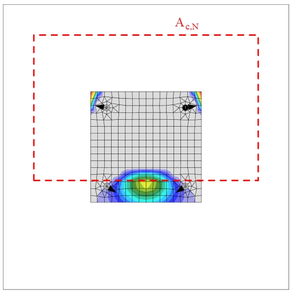
The concrete breakout cone area for group of anchors loaded by tension that create common concrete cone, Ac,N, is shown by red dashed line.
Steel failure in shear
Steel failure in shear is determined according to Cl. 9.2.3. It is assumed that the anchor is made of threaded rod with the same material properties as bolts.
Shear force without lever arm
Shear resistance is checked according to IS 1946:2025 – 9.2.3.1:
where:
- – characteristic resistance of a fastener in case of steel failure
- – product dependent factor assumed
- – the characteristic shear strength
- – tensile stress area
- – ultimate strength of the anchor bolt
- – partial safety factor for steel failure for shear loading
- for MPa and
- for MPa or
- – yield strength of the anchor bolt
Shear force with lever arm
Shear resistance is checked according to IS 1946:2025 – 9.2.3.2:
where:
- – characteristic resistance of a fastener in case of steel failure with lever arm
- – factor accounting for the degree of restraint of the fastener, assumed because anchor is clamped by two nuts and base plate is more rigid than the anchor
- – characteristic flexural strength of the fastener influenced by the axial load
- – design tension load
- – tensile strength of a fastener to steel failure
- – characteristic flexural strength of the fastener
- – elastic section modulus of the fastener
- – anchor diameter reduced by threads
- – ultimate strength of the anchor bolt
- – length of the lever arm
- – anchor diameter
- – thickness of grout layer
- – base plate thickness
- – partial safety factor for steel failure for shear loading
- for MPa and
- for MPa or
- – yield strength of the anchor bolt
Concrete edge failure
Concrete edge failure resistance is checked according to IS 1946:2025 – 9.2.3.4. If concrete cones of fasteners intersect, they are checked as a group. The edges in the direction of the shear load are checked. All load at a base plate is presumed to be transferred by a fastener near the checked edge.
where
- – initial value of the characteristic shear strength of the fastener
- for cracked concrete
- for uncracked concrete
- – anchor diameter
- – factor
- – parameter related to the length of the fastener
- – embedment depth
- – factor
- – characteristic cube compression strength of concrete
- – edge distance of fastener in direction 1 towards the edge in the direction of loading
- – concrete member thickness
- – larger of the two distances to the edges parallel to the direction of loading
- – maximum spacing in direction 2 between fasteners within a group
- – reference projected area of failure cone
- – actual area of idealised concrete break-out body
- – parameter related to the distribution of stresses in the concrete due to the proximity of the fastener to an edge of the concrete member
- – edge distance of fastener in direction 1 towards the edge in the direction of loading
- – edge distance perpendicular to direction 1 that is the smallest edge distance in a narrow member with multiple edge distances
- – parameter accounting for the shell spalling effect, no edge reinforcement or stirrups are assumed
- – modification factor for anchor groups loaded eccentrically in shear
- – shear load eccentricity
- – modification factor for anchors located in a shallow concrete member
- – modification factor for anchors loaded at an angle with the concrete edge
- – angle between the applied load to the fastener or fastener group and the direction perpendicular to the free edge under consideration
- – partial safety factor for concrete failure
- – partial safety factor for concrete
- – installation safety factor of an anchor system in shear
Interaction of tensile and shear forces in steel
The interaction of tensile and shear forces in steel is performed for anchors with stand-off: Direct according to IS 1946:2025 – 9.2.4:
where:
- – design tension force
- – fastener tensile strength
- – design shear force
- – fastener shear strength
Steel interaction is not required in case of shear load with lever arm. It is covered by shear load with lever arm equation.
Interaction of tensile and shear forces in concrete
Interaction of tensile and shear forces in concrete is checked according to IS 1946:2025 – 9.2.4:
where:
- – the largest utilization value for tension failure modes
- – the largest utilization value for shear failure modes
- – concrete breakout failure of anchor in tension
- – concrete edge failure
Anchors with stand-off: Gap
Anchors with stand-off: gap in tension are designed according to IS 1946:2025, and anchors in compression are designed as a beam member according to IS 800: 2007 with partial safety factor of anchors. The assumed length of the member is the sum of the height of gap, half of nominal diameter thickness and half of the base plate thickness. Stand-off anchors are usually checked at a construction stage before grouting.
Steel failure in tension is checked according to IS 1946:2025 – 9.2.2.2:
Steel failure in compression is checked according to IS 800:2007 – 7.1:
where:
- – anchor area reduced by thread
- – design compressive stress
- – buckling reduction factor
- – value to determine buckling reduction factor
- – imperfection factor
- – relative slenderness
- – Euler buckling stress
- – elastic modulus
- – buckling length
- – length of the lever arm
- – anchor diameter
- – thickness of grout layer
- – base plate thickness
- – radius of gyration of the anchor bolt
- – moment of inertia of the bolt
- – anchor diameter reduced by threads
- – partial safety factor for steel failure for tension loading
- – yield strength of the anchor bolt
- – ultimate strength of the anchor bolt
Shear resistance is checked according to IS 1946:2025 – 9.2.3.1:
Bending resistance is checked according to IS 1946:2025 – 9.2.3.2:
where:
- – characteristic flexural strength of the fastener
- – elastic section modulus of the fastener
- – anchor diameter reduced by threads
- – yield strength of the anchor bolt
- – ultimate strength of the anchor bolt
Interaction of loading for anchors in tension (IS 1946:2025 – 9.2.4):
where:
- – design tension force
- – design tensile resistance
- – design bending moment
- – design bending resistance
Interaction of loading for anchors in compression (IS 1946:2025 – 9.2.4):
where:
- – design compression force
- – design compression resistance
- – design bending moment
- – design bending resistance
Concrete-related failure modes, including their interaction, are checked as for the standard anchors according to IS 1946:2025.
Detailing
If anchors with MPa are used, steel strength for shear load may not be accurate, use steel strength from AR instead.
Detailing of bolts and welds according to Indian Standard
Bolts
Bolt minimum spacing is according to IS 800, Cl. 10.2.2: Centre to centre of the bolt should be larger than , where is nominal bolt diameter.
Minimum end and edge distances measured from the centreline of the bolt are taken according to IS 800, Cl. 10.2.4 as , where is the standard hole diameter according to IS 800, Table 19.
The grip length of bolts should be limited to according to IS 800, Cl. 10.3.3.2.
Welds
Minimal size of welds is checked according to IS 800, Table 21:
| Thickness of thicker part [mm] | Minimal weld size [mm] |
| 3 | |
| 5 | |
| 6 | |
| 10 |
Note that weld size is assumed as throat thickness multiplied by .
Column base
Column base thickness should be larger than the thickness of column flange according to IS 800, Cl. 7.4.3.1.
Capacity design according to Indian Standard
Plastic hinge is expected to appear in dissipative item and all non-dissipative items of the joint must be able to safely transfer forces due to the yielding in the dissipative item. The dissipative item is usually a beam in moment resisting frame. The safety factor is not used for dissipative items:
Two factors are assigned to the dissipative item:
- – overstrength factor – IS 800, Cl. 12; the recommended value is ; editable in materials
- – strain-hardening factor; the recommended value is ; editable in operation
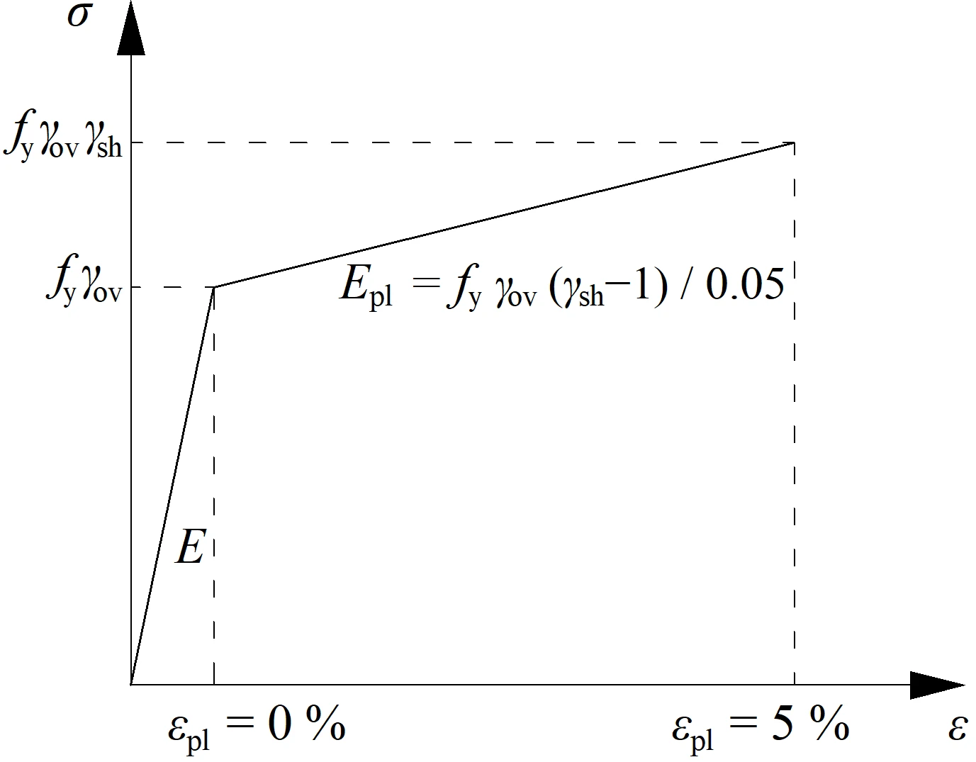
The increased strength of the dissipative item allows for the input of loads that cause the plastic hinge to appear in the dissipative item. In the case of moment resisting frame and beam as the dissipative item, the beam should be loaded by and corresponding shear force , where:
- – characteristic yield strength
- – plastic section modulus
- – distance between plastic hinges on the beam
In the case of an asymmetric joint, the beam should be loaded by both sagging and hogging bending moments and their corresponding shear forces.
The plates of dissipative items are excluded from the check.
Classification according to stiffness for Indian standard
Joints are classified according to joint stiffness to:
- Rigid – joints with insignificant change of original angles between members,
- Semirigid – joints which are assumed to have the capacity to furnish a dependable and known degree of flexural restraint,
- Pinned – joints that do not develop bending moments.
Joints are classified according to the EN 1993-1-8 – Cl. 5.2.2.
- Rigid –
- Semirigid –
- Pinned –
where:
- Sj,ini – initial stiffness of the joint; the joint stiffness is assumed linear up to the 2/3 of Mj,Rd
- Lb – theoretical length of the analyzed member; set in member properties
- E – Young's modulus of elasticity
- Ib – moment of inertia of the analyzed member
- kb = 8 for frames where the bracing system reduces the horizontal displacement by at least 80 %; kb = 25 for other frames, provided that in every storey Kb/Kc ≥ 0.1. The value of kb = 25 is used unless the user sets "braced system" in Code setup.
- Mj,Rd – joint design moment resistance
- Kb = Ib / Lb
- Kc = Ic / Lc