The display of the results is very similar to 2D Detail. However, there are some major differences, especially when it comes to results on concrete and results of anchors. In the following section, we will go through all the available results, focusing on the differences mentioned. In the check tab you can view a total of 4 types of results:
- Summary
- Strength and Achor check based on codes
- Anchorage of the reinforcement
- Other additional results
Stress flow in Summary results shows you the vectors of compression principal stresses in concrete and utilization of the reinforcement and anchors to give you a basic overview.

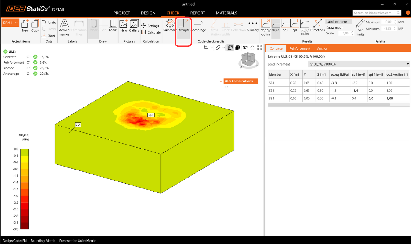
Strength check of concrete, reinforcement and anchors
In the Strength check you can display the redistribution of stresses and strains for oncrete. In the top ribbon in the Results toolbar, you can control what will be displayed. It is also possible to display, the ratios σc,eq/σlim, and ε/εlim as well as the plastic strain, the level of triaxiality σc3/σlim, and the direction of principal stress for concrete. All results in the Strength are related to the Ultimate Limit State.
Note: You may notice that the Equivalent Principal stress σc,eq is zero just below the compressed base plate. Please read the Theoretical background where the σc,eq is defined. Or you can go through this verification article, where this phenomenon is explained and verified using a well-known tri-axial test: Tri-axial stress – the active confinement effect
Materials can be switched in properties.
The check for reinforcement is performed in a very similar way, where we again compare the limit values with the calculated stress/strain - σs/σlim, and εs/εlim.

For or anchors, we have two checks. One is the same as for reinforcement — comparing the limit values - σs/σlim, and εs/εlim.
Note: You may notice that each anchor is verified in several positions, which are automatically calculated as extreme cases.
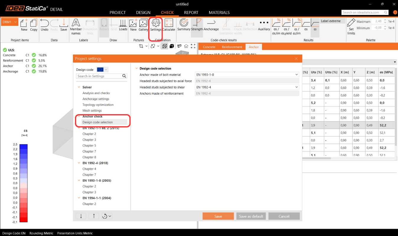
Code-checking of anchors according to the design code
In addition, we have design code based checks (EN, ACI/AISC, AUS), which are done empirically according to the standard. The specific standard considered can be seen in the settings, where it is also possible to select a different one depending on the type of anchorage used (base plate in direct contact with concrete, grouted base plate, and base plate with a gap), as well as the required standard based on regional practices.

Implemented codes: EN 1992-4, EN 1993-1-8, EN 1994-1-1, ACI318-19, AISC 360-16, AS3600, AS 5216, AS 4100
The standard settings can be changed in Project Settings, where the chapters will appear according to the standard selected when the project was created. When importing from Connection, It is recommended to check that the same standard is set.
In the Theoretical Background chapter - Ultimate Limit State Checks, each check is explained in detail, including all formulas used.
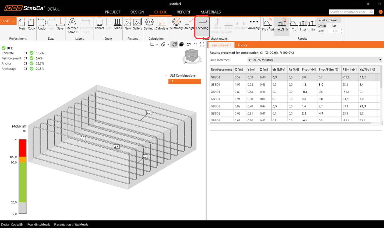
Anchorage of reinforcement
Anchorage check gives you information about bond stress and total force on the reinforcement and anchors.
Surface support reactions
Reactions and Loads section includes an option to display surface support reactions. Reactions can be viewed in two modes:
- Intensity – Surface reactions are shown on the supported face of the concrete block using isobands to illustrate distribution over the support area.

- Resultant – The resultant reaction for each support is displayed as an arrow at the support’s center of gravity, indicating magnitude and direction.

For both modes, reactions can be displayed in either the Global Coordinate System (GCS) or the Local Coordinate System (LCS) of the support.
A new table in the Property Grid lists summarized reactions for individual supports, also available in global or local coordinates.

Additionally, reaction distribution can be visualized in section views created by the user.

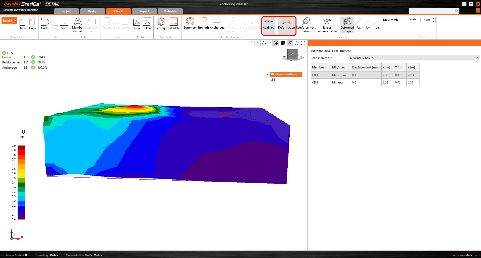
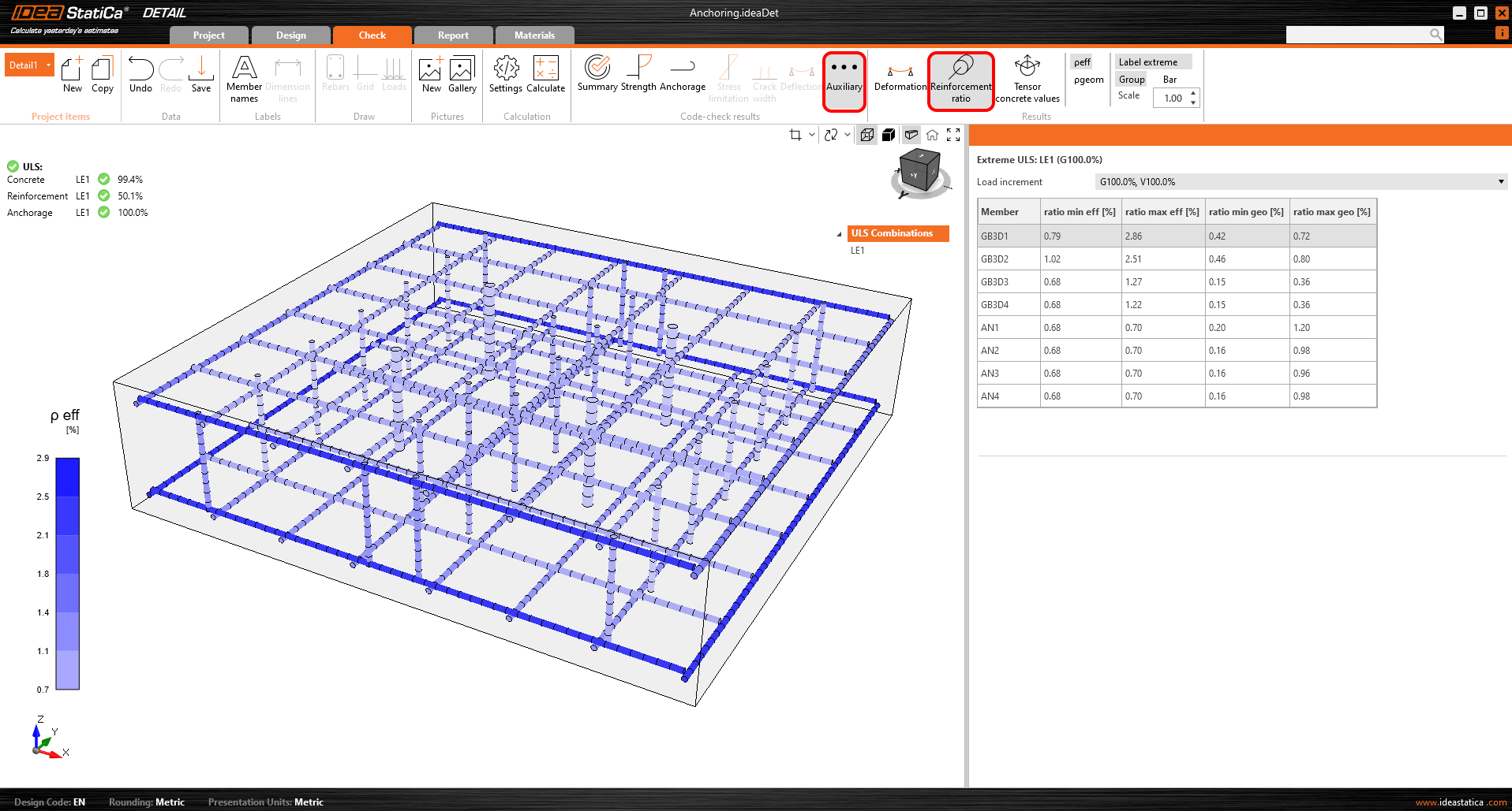
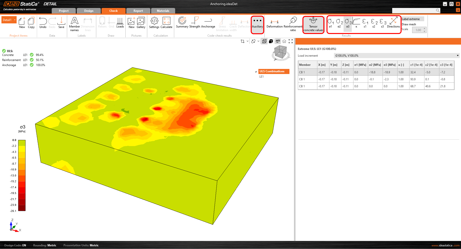
Additional advanced results
Last but not least, you can view the Auxiliary results in the application - Deformation, Reinforcement ratio, and Tensor concrete values. The first type, Deformation, can display scaled deformations of the ULS non-linear model.
The Reinforcement ratio shows the values used to compute the Tension stiffening effect.
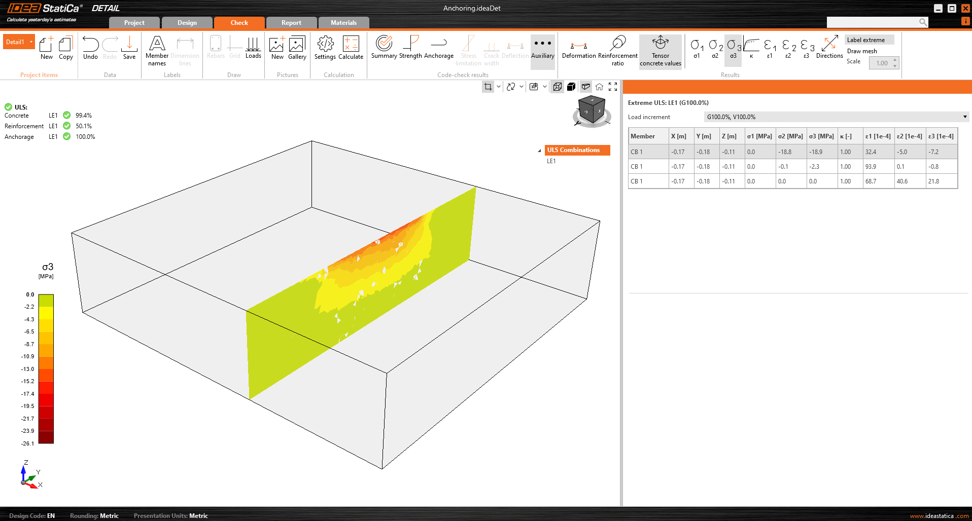
Tensor concrete values allow you to display the intensities of principal stresses in concrete and their direction.
The result sections can also be used.