L'affichage des résultats est très similaire à celui du Detail 2D. Cependant, il existe quelques différences majeures, notamment en ce qui concerne les résultats sur le béton et les résultats des ancrages. Dans la section suivante, nous passerons en revue tous les résultats disponibles, en nous concentrant sur les différences mentionnées. Dans l'onglet de vérification, vous pouvez consulter 4 types de résultats :
- Récapitulatif
- Vérification de la résistance et des ancrages selon les codes
- Ancrage du ferraillage
- Autres résultats supplémentaires
Le flux de contraintes dans les résultats du Récapitulatif vous montre les vecteurs des contraintes principales de compression dans le béton et le taux de travail du ferraillage et des ancrages pour vous donner un aperçu général.

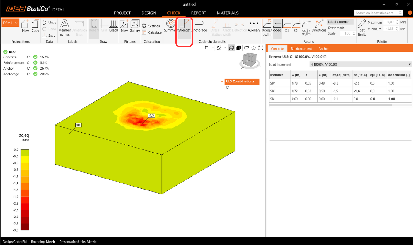
Vérification de la résistance du béton, du ferraillage et des ancrages
Dans la vérification de la Résistance, vous pouvez afficher la redistribution des contraintes et des déformations pour le béton. Dans le ruban supérieur de la barre d'outils Résultats, vous pouvez contrôler ce qui sera affiché. Il est également possible d'afficher les rapports σc,eq/σlim, et ε/εlim ainsi que la déformation plastique, le niveau de triaxialité σc3/σlim, et la direction de la contrainte principale pour le béton. Tous les résultats de la Résistance sont liés à l'État Limite Ultime.
Remarque : Vous pouvez remarquer que la contrainte principale équivalente σc,eq est nulle juste en dessous de la platine de base comprimée. Veuillez lire le Contexte théorique où σc,eq est définie. Ou vous pouvez consulter cet article de vérification, où ce phénomène est expliqué et vérifié à l'aide d'un essai triaxial bien connu : Contrainte triaxiale – l'effet de confinement actif
Les matériaux peuvent être modifiés dans les propriétés.
La vérification du ferraillage est effectuée de manière très similaire, où nous comparons à nouveau les valeurs limites avec la contrainte/déformation calculée - σs/σlim, et εs/εlim.

Pour les ancrages, nous disposons de deux vérifications. L'une est identique à celle du ferraillage — comparaison des valeurs limites - σs/σlim, et εs/εlim.
Remarque : Vous pouvez remarquer que chaque ancrage est vérifié en plusieurs positions, qui sont automatiquement calculées comme des cas extrêmes.
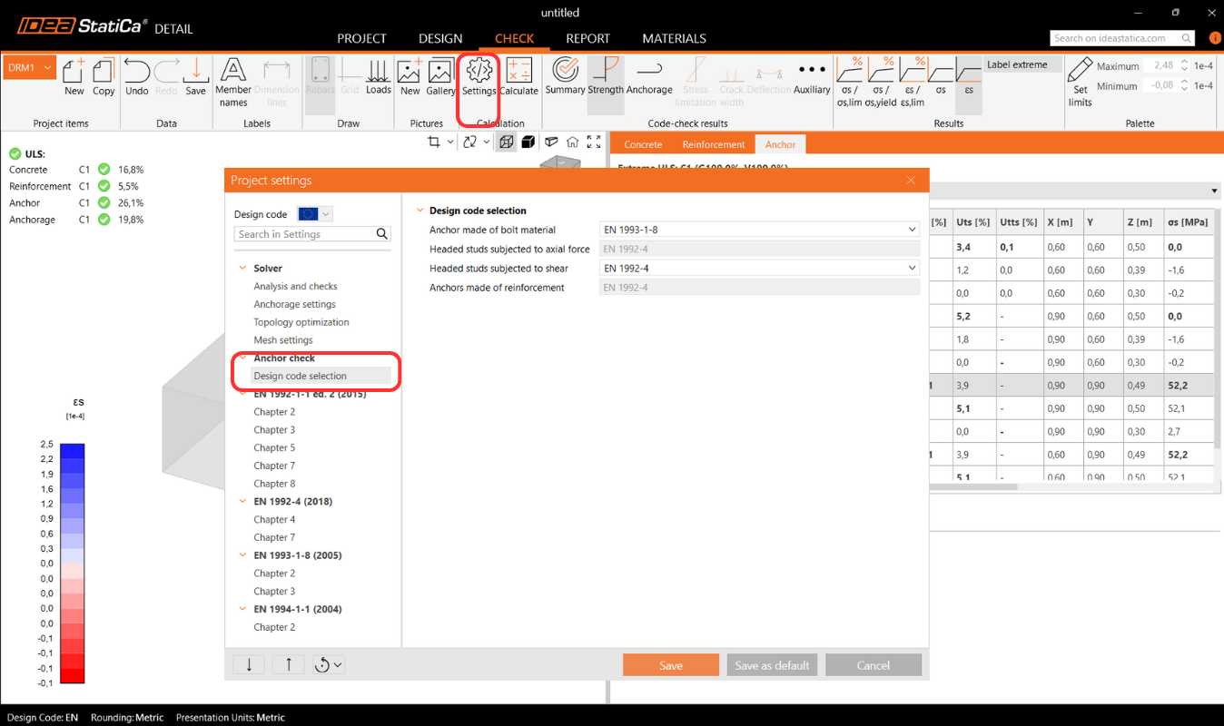
Vérification normative des ancrages selon le code de calcul
De plus, nous disposons de vérifications basées sur les codes de calcul (EN, ACI/AISC, AUS), qui sont effectuées de manière empirique conformément à la norme. La norme spécifique considérée peut être consultée dans les paramètres, où il est également possible d'en sélectionner une autre en fonction du type d'ancrage utilisé (platine de base en contact direct avec le béton, platine de base scellée au mortier, et platine de base avec jeu), ainsi que la norme requise selon les pratiques régionales.

Codes implémentés : EN 1992-4, EN 1993-1-8, EN 1994-1-1, ACI318-19, AISC 360-16, AS3600, AS 5216, AS 4100
Les paramètres de la norme peuvent être modifiés dans les Paramètres du projet, où les chapitres apparaîtront selon la norme sélectionnée lors de la création du projet. Lors de l'importation depuis Connection, il est recommandé de vérifier que la même norme est définie.
Dans le chapitre Contexte théorique - Vérifications à l'État Limite Ultime, chaque vérification est expliquée en détail, y compris toutes les formules utilisées.
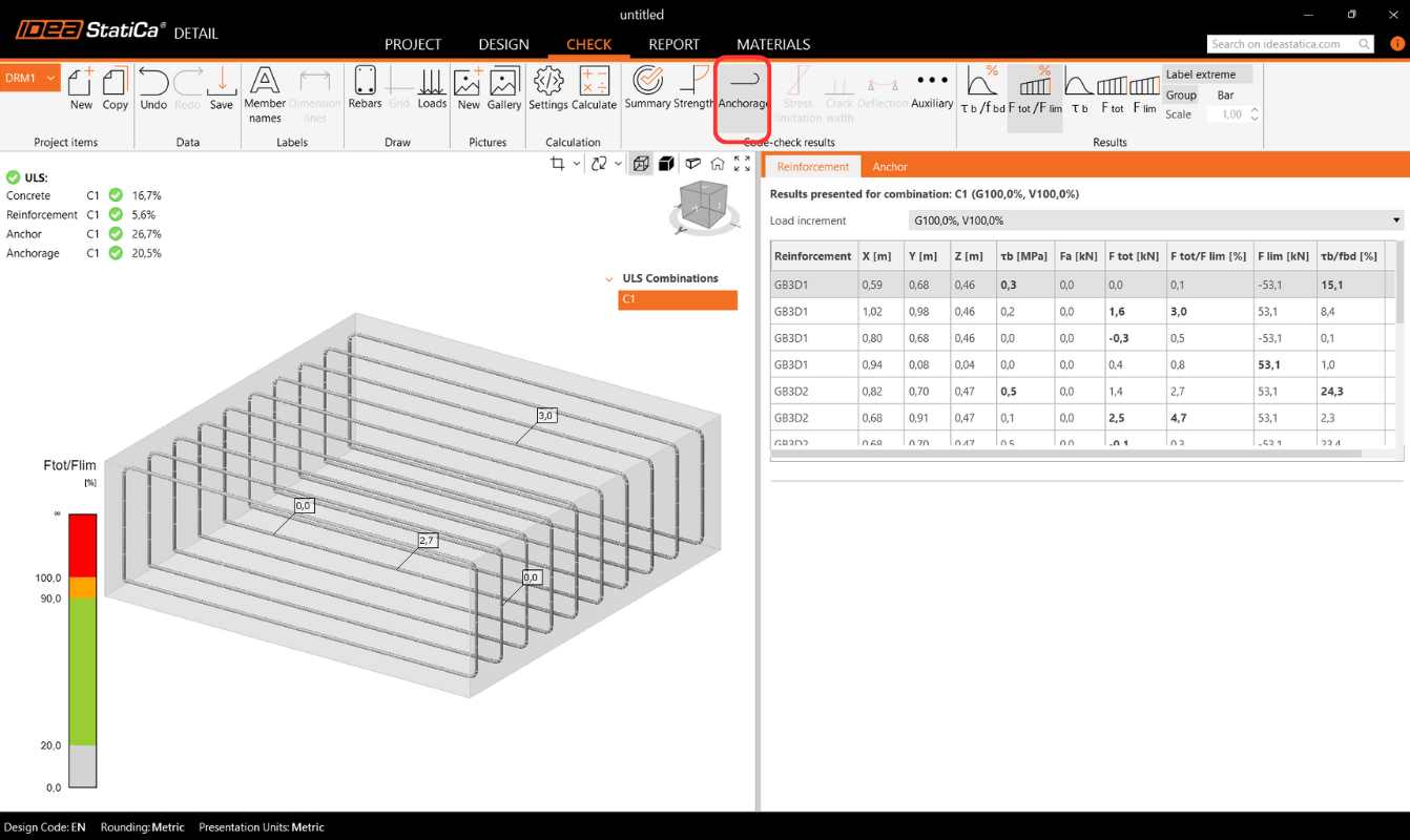
Ancrage du ferraillage
La vérification de l'Ancrage vous fournit des informations sur la contrainte d'adhérence et l'effort total sur le ferraillage et les ancrages.
Réactions d'appui surfaciques
La section Réactions et Charges inclut une option pour afficher les réactions d'appui surfaciques. Les réactions peuvent être visualisées selon deux modes :
- Intensité – Les réactions surfaciques sont affichées sur la face appuyée du bloc de béton à l'aide d'isobandes pour illustrer la distribution sur la zone d'appui.

- Résultante – La réaction résultante pour chaque appui est affichée sous forme de flèche au centre de gravité de l'appui, indiquant la magnitude et la direction.

Pour les deux modes, les réactions peuvent être affichées soit dans le Système de Coordonnées Global (SCG) soit dans le Système de Coordonnées Local (SCL) de l'appui.
Un nouveau tableau dans la Grille de Propriétés liste les réactions récapitulatives pour les appuis individuels, également disponibles en coordonnées globales ou locales.

De plus, la distribution des réactions peut être visualisée dans les vues en coupe créées par l'utilisateur.

Résultats avancés supplémentaires
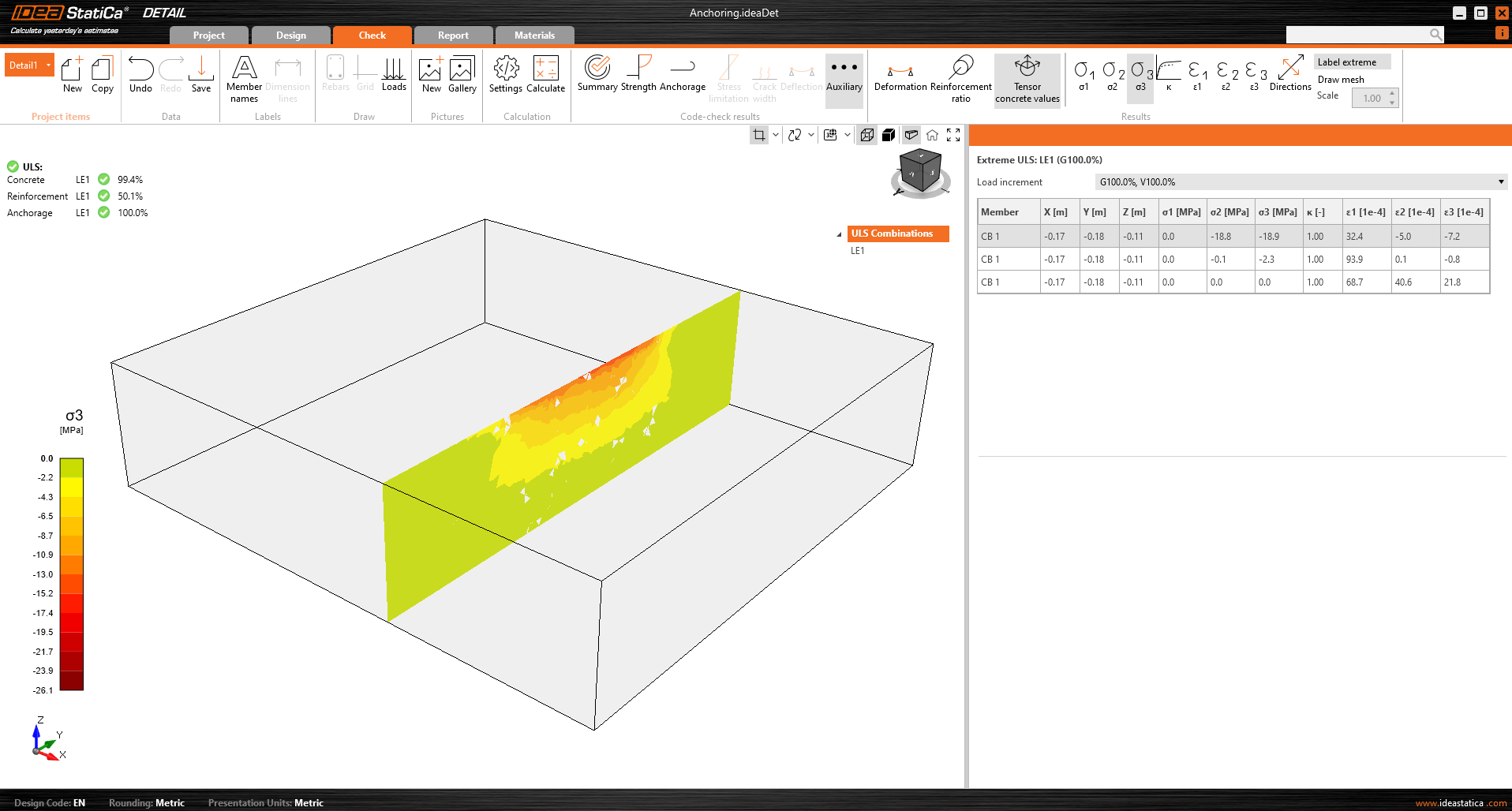
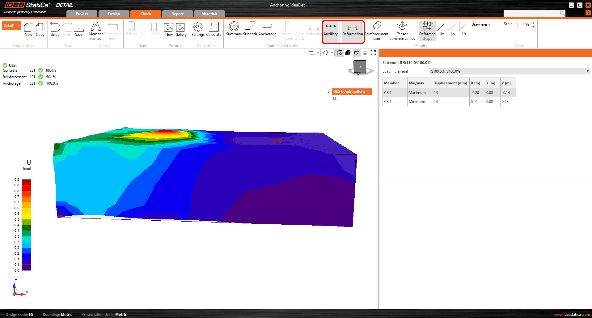
Enfin, vous pouvez consulter les résultats Auxiliaires dans l'application - Déformation, Taux de ferraillage et Valeurs tensorielles du béton. Le premier type, Déformation, peut afficher les déformations à l'échelle du modèle non linéaire à l'ELU.
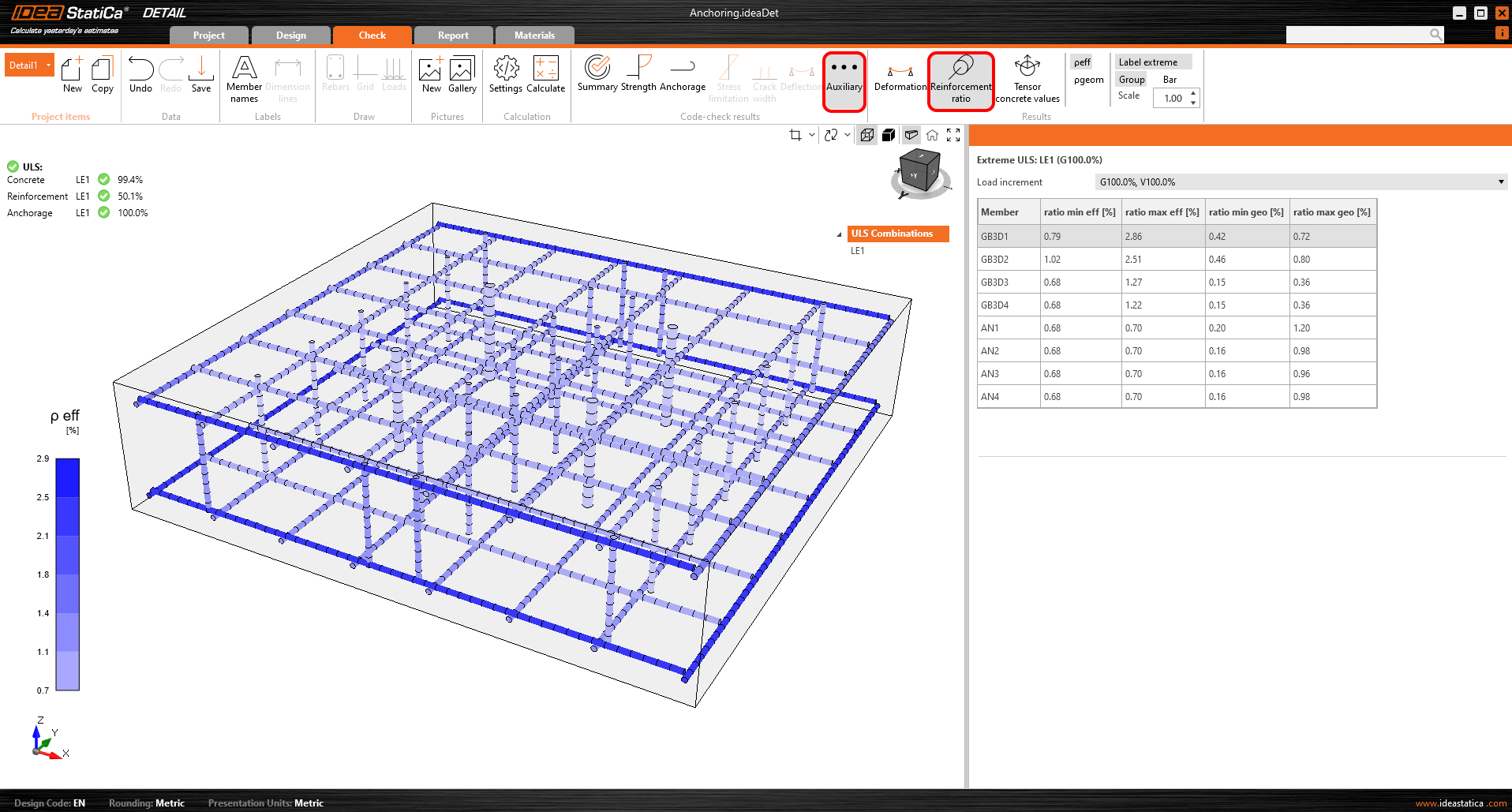
Le taux de ferraillage affiche les valeurs utilisées pour calculer l'effet de raidissement en traction.
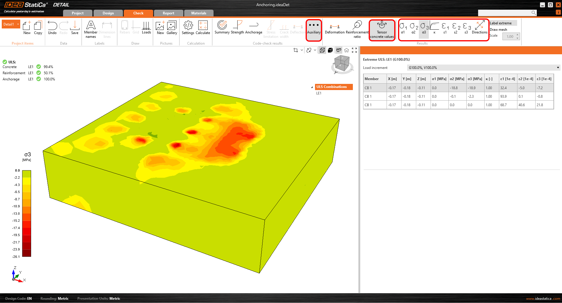
Les valeurs tensorielles du béton vous permettent d'afficher les intensités des contraintes principales dans le béton et leur direction.
Les sections de résultats peuvent également être utilisées.