MIDAS CIVIL NX BIM link for steel connection design

By following this step-by-step tutorial, you will learn how to design and code-check a structural steel connection using the BIM link between MIDAS CIVIL NX and IDEA StatiCa Checkbot.

1 Activation 

Since version midas Civil NX 2024 and newer, the API has been added, and due to this new possibility, the new link to IDEA Statica Checkbot was created.

In the following figures, you can see how to activate the link.

inline image in article

Press YES when the User Account Control asks for permission to make changes to your device.

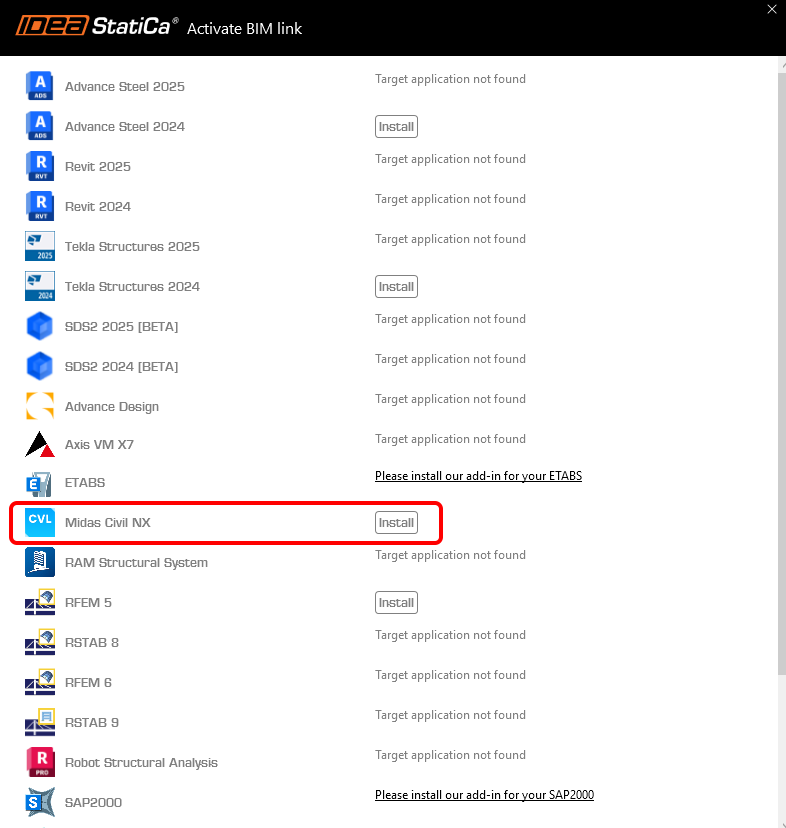
Install midas Civil NX BIM link.

inline image in article

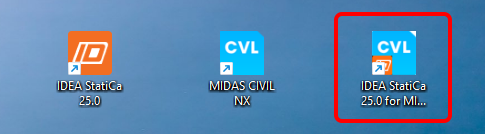
Subsequently, the new icon appears on the Desktop.

inline image in article

Now run midas Civil NX and open the new or existing project.

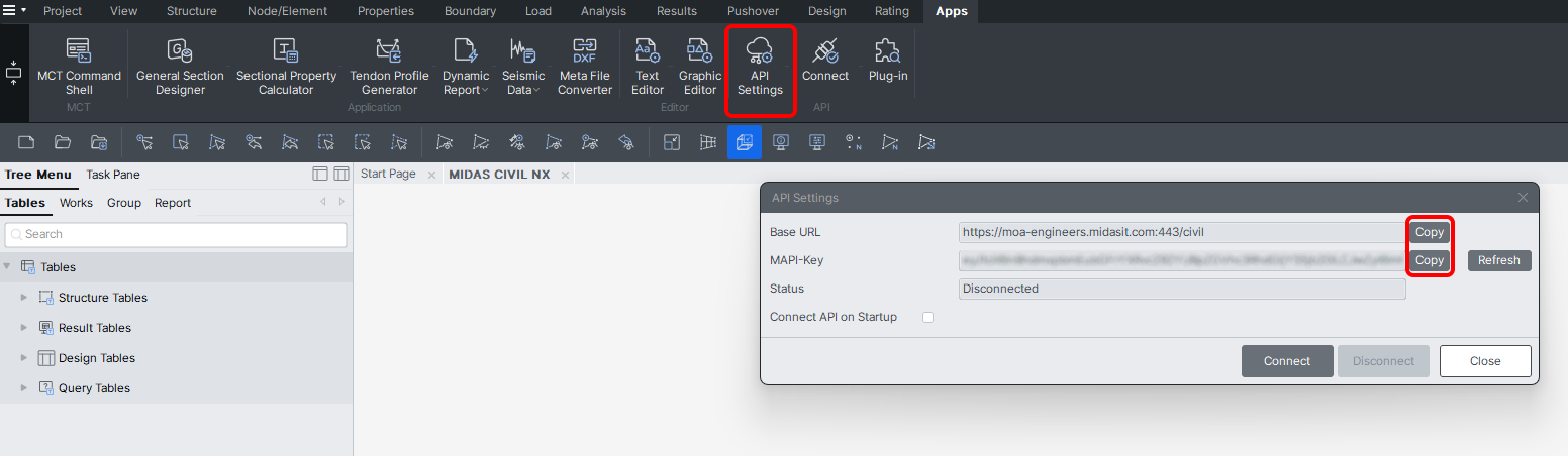
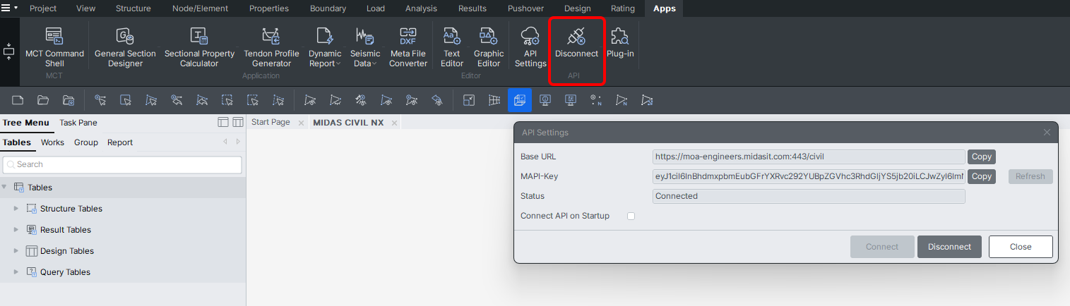
In the ribbon, in the last tab APPs, there is API Settings, where the Base URL and MAPI-Key are given. The MAPI-Key is unique for every user and shouldn´t be shared with others. The Copy button can be used to copy them. 

Connect to the API. 

inline image in article

The API is connected when the Tab changed to "Disconnect".

inline image in article

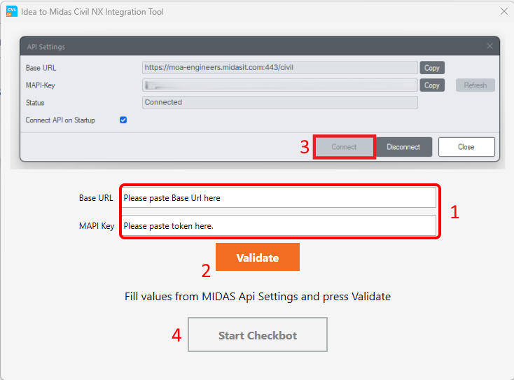
Open the IDEA to MIDAS CIVIL NX Integration Tool from the Desktop and paste the copied Base URL and MAPI Key from your opened MIDAS CIVIL NX project (1). Then, Validate (2) and connect to Civil NX (3). After that, Start Checkbot (4).

inline image in article

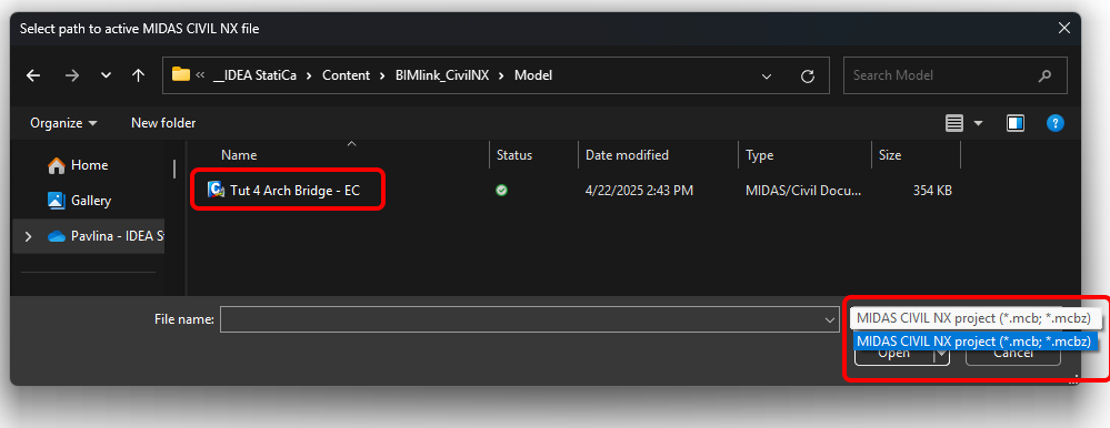
Select path to active MIDAS CIVIL NX file and open it. Both .mcb and .mcbz file formats can be chosen.

inline image in article

Create the New project in Checkbot.
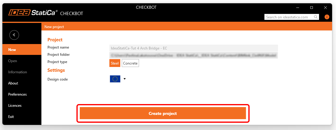
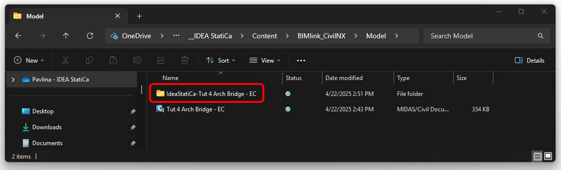
inline image in article

The Chekbot folder is created in the same folder as the MIDAS CIVIL NX project.

inline image in article

After that, a new project is opened. The Checkbot is connected to Civil NX (look at the bottom right corner).

inline image in article

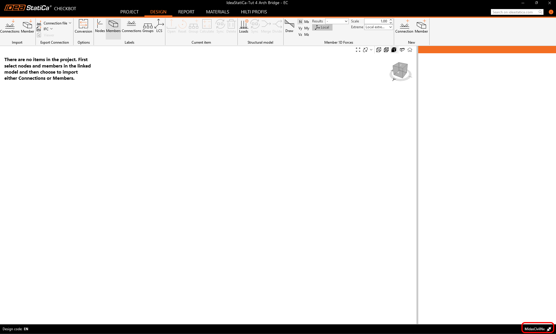
2 Import to Checkbot

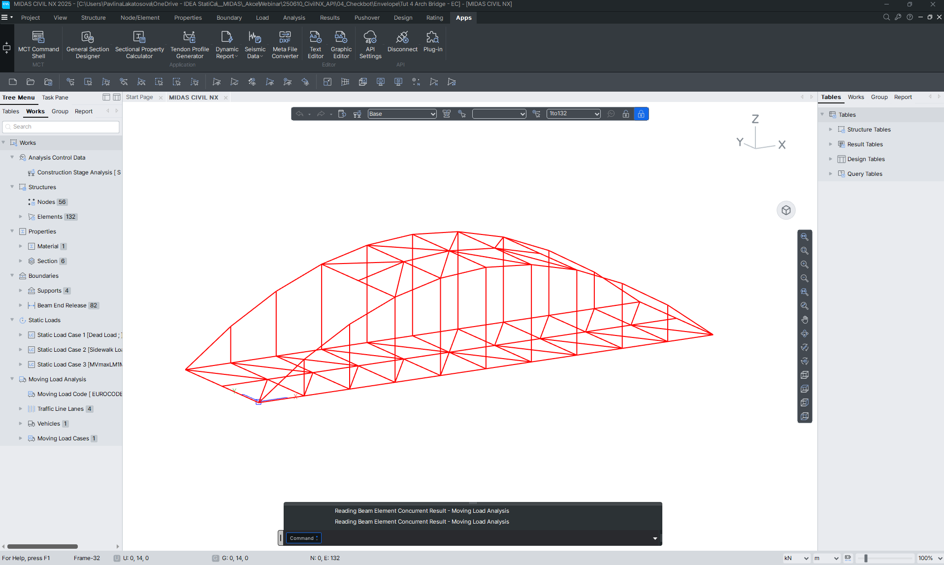
At first, run the linear analysis in Civil NX to get the internal forces. 

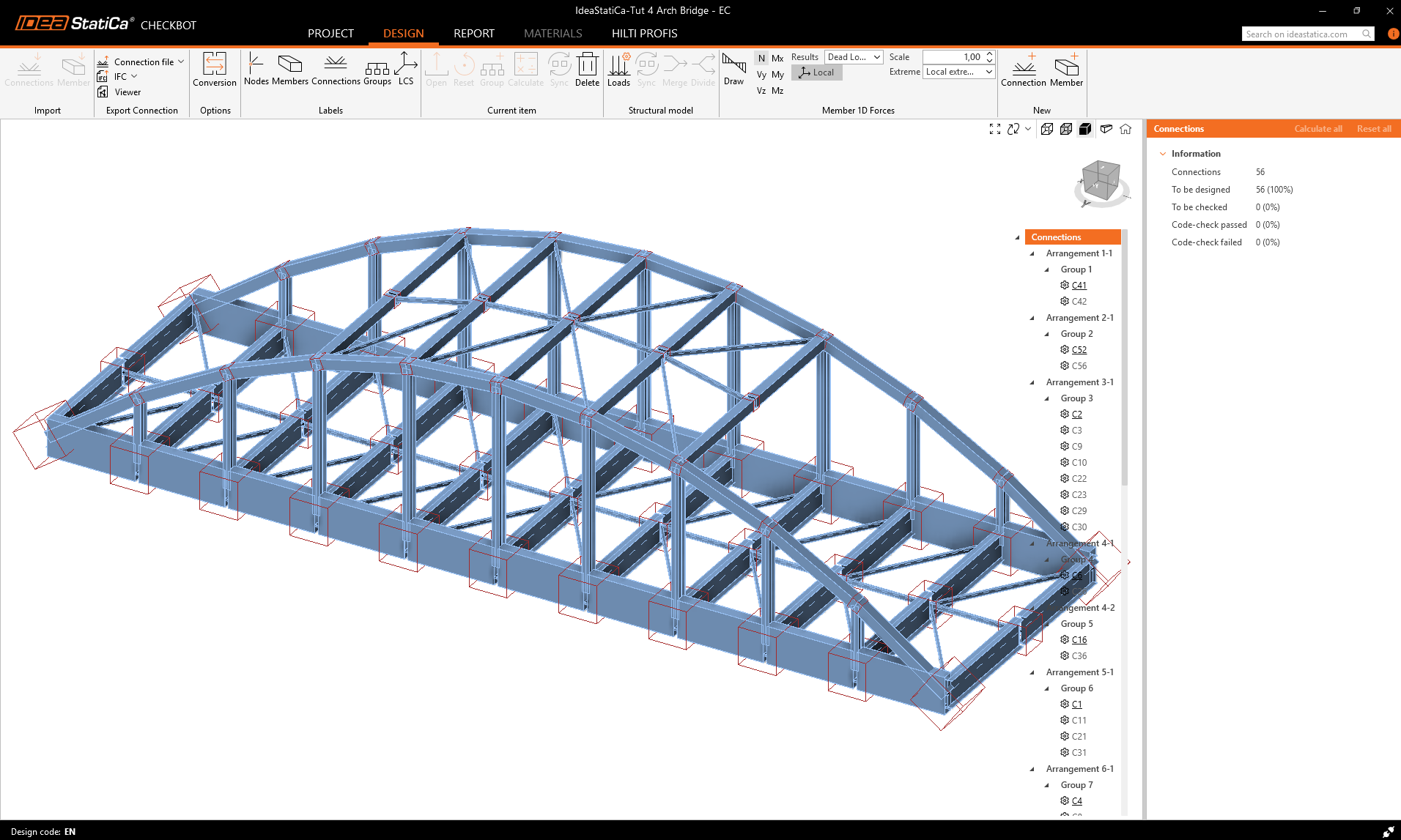
After analysis, you can import the whole model. To do so, select all the elements. 

inline image in article

Click on the Connections Import tab.

inline image in article

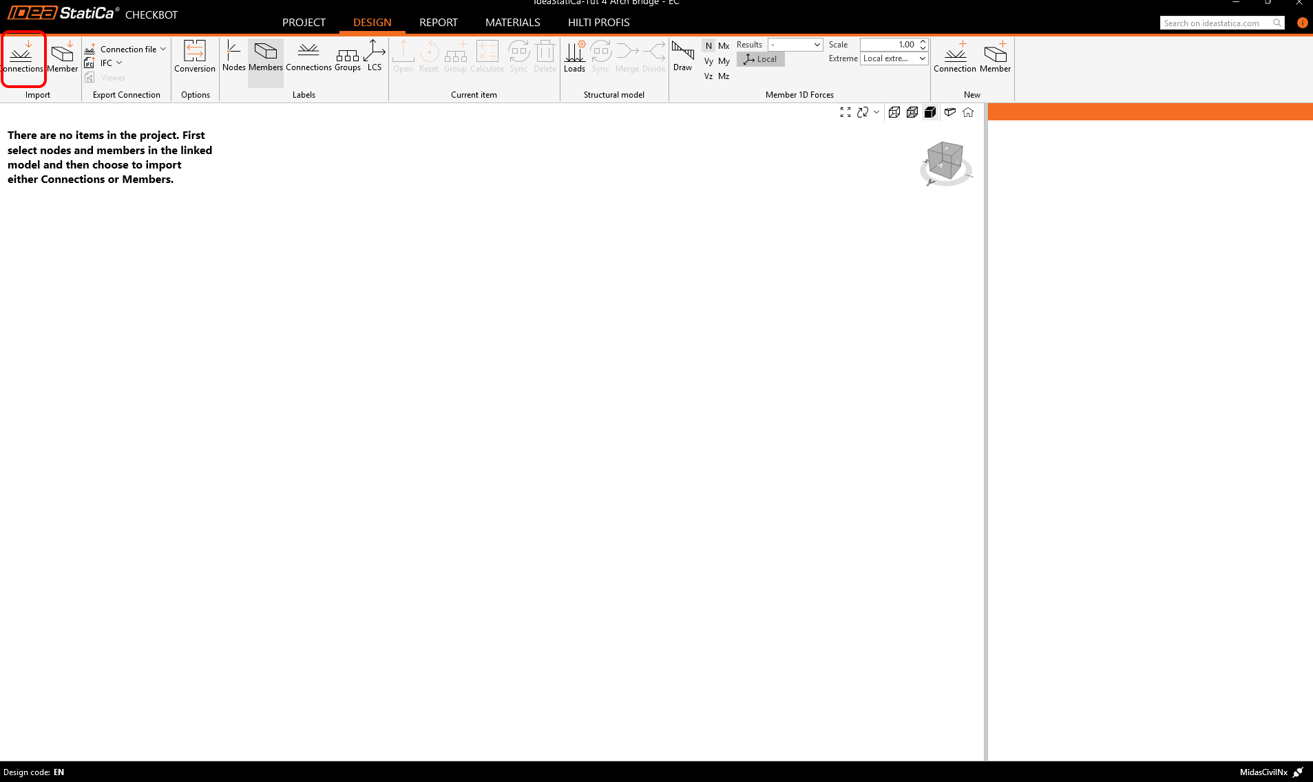
The whole structure has been imported.

inline image in article

Alternatively, the connections could be imported one by one by selecting only one or more connections. The connections of the same typology are sorted into one arrangement or group.

More about the workflow in the Checkbot, see the article Checkbot – bulk BIM workflows.

3 Connection Design

Select the connection C2 (corresponds to the node number N2 in Civil NX) and click on the Open button in the ribbon. 

inline image in article

The connection in the IDEA StatiCa Connection is opened. There are no unbalanced forces, which means the load is in equilibrium. This is an essential step for controlling the correctness of your model.

inline image in article

The operations will now be added to the joint design. First, use the operation Cut for the members M1 and M2.

inline image in article

Add a Stiffening plate in the middle of the cross-section. 

inline image in article

Then apply the operation Cut to all four sides of the member M1.

inline image in article

Next will be the  Cut of Member M11 with a distance of 30 mm.

inline image in article

To connect the upper belt with the member M11, we add a Stiffening member - U400

inline image in article

Apply the Cut operation to the Stiffening member SM1 according to the picture to connect it to member M1.

inline image in article

The last Operation is the Operation Fastener grid or Contact, in which we add two rows of M22 8.8 bolts.

inline image in article

5 Check

Run the analysis. You will obtain results for all components, such as plates, welds, bolts, and equations, according to the code describing all results.

inline image in article

Let's look at the equivalent stress on the plates turned on the mesh and deformed shape with the tab, where the stresses are sorted gradually from maximum to minimum.  

inline image in article

6 Report

Next, go to the tab Report. IDEA StatiCa offers a fully customizable report to print out or save in an editable format. The printed-out format can be PDF and doc. file.

inline image in article

Known limitations

  • For now, importing only steel connections (no concrete) is possible.
inline image in article
  • All nodes are imported as connections.

Also, the intermediate nodes are imported as connections.

  • Only linear combinations. 

Midas Civil NX is a powerful tool for the calculation of envelopes from moving load or settlement analysis. IDEA StatiCa Checkbot can not work with the envelopes from the midas Civil NX. If you want to do the code - check the combinations with the impact of moving load, it is essential to create a static load case from the moving load analysis.  

Static load case for node 16 and maximal bending moment My on the member 24 was selected for the actual combination LCB1 imposed in the Midas Civil and also in IDEA StatiCa Connection. 

inline image in article
  • Nodal loads are not imported; only internal force imports are available. 

This limitation could cause unbalanced forces in the connection due to nodal loads being entered directly in the node, which basically do not create internal forces on the members.

inline image in article


Sample files

Want to improve your skills? Visit our Campus

Learn how to use IDEA StatiCa effectively with our self-paced e-learning courses

Attached Downloads