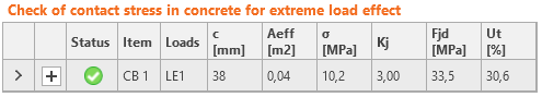
Concrete below the base plate is simulated by the Winkler subsoil with uniform stiffness, which provides the contact stresses. The average stress at the effective area determined by EN 1993-1-8 is used for compressive check.
The resistance of concrete in 3D compression is determined based on EN 1993-1-8 by calculating the design bearing strength of concrete in the joint, fjd, under the effective area, Aeff, of the base plate. The design bearing strength of the joint, fjd, is evaluated according to Cl. 6.2.5 in EN 1993-1-8 and Cl. 6.7 in EN 1992-1-1. The grout quality and thickness is introduced by the joint coefficient, βjd. For grout quality equal or better than the quality of the concrete block, βjd = 1.0 is expected, EN 1993-1-8 recommends value βjd = 0.67. The effective area, Aeff,cm under the base plate is estimated to be of the shape of the column cross-section increased by additional bearing width, c.
\[ c = t \sqrt{\frac{f_y}{3 f_{jd} \gamma_{M0}}} \]
where t is the thickness of the base plate, fy is the base plate yield strength, and γM0 is the partial safety factor for steel.
The effective area is calculated by iteration until the difference between the additional bearing widths of current and previous iteration |ci – ci–1 | is less than 1 mm. For the first iteration, the area of the base plate is assumed as a bearing area, Ac0.
The area where the concrete is in compression is taken from results of FEA. This area in compression, Aeff,FEM, allows determining the position of the neutral axis. The user can modify this area by editing “Effective area – influence of mesh size” in Code setup. The default value is 0.1 for which the verification studies were made. It is not recommended to decrease this value. Increasing this value makes the assessment of concrete bearing resistance safer. The value in Code setup determines the boundary of the area, Aeff,FEM, e.g. the value of 0.1 takes into account only areas where stress in concrete is higher than 0.1 times the maximum stress in concrete, σc,max. The intersection of the area in compression, Aeff,FEM, and the effective area, Aeff,cm, allows to assess the resistance for generally loaded column base of any column shape with any stiffeners and is labeled Aeff. The average stress σ on the effective area, Aeff, is determined as the compression force divided by the effective area. Check of the component is in stresses σ ≤ fjd.
Concrete resistance at concentrated compression:
\[ f_{jd}= \beta_j k_j \frac{f_{ck}}{\gamma_c} \]
Concentration factor taking into account increase in concrete compressive resistance due to triaxial stress:
\[ k_j=\sqrt{\frac{A_{c1}}{A_{eff}}} \le 3.0 \]
where Ac1 is the supporting area determined according to EN 1992-1-1 – Cl. 6.7. The area must be concentric and geometrically similar to the bearing area Aeff.
Average stress under the base plate:
\[ \sigma = \frac{N}{A_{eff}} \]
Utilization in compression [%]:
\[ Ut = \frac{\sigma}{f_{jd}} \]
where:
- fck – characteristic compressive concrete strength
- βj = 0.67 – factor of grout quality editable in Code setup
- γc – safety factor for concrete
- Aeff – effective area on which the column normal force N is distributed
Effective area, Aeff,cm, as calculated according to EC for pure compression, is marked with a dashed line. The graphical representation shows the way of checking. Calculated effective area, Aeff,fem, is marked as green. The final effective area, Aeff, for contact stress check is highlighted as hatched.
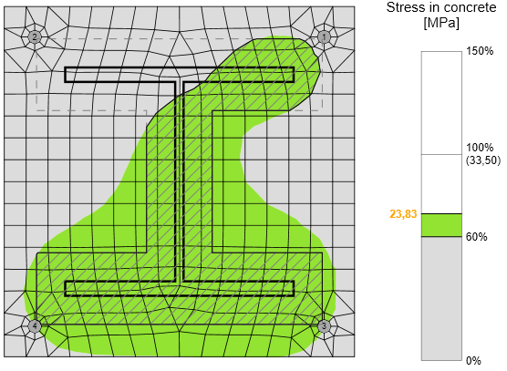
For rare occasions, especially for column base loaded by tensile force only (compression in concrete is caused by prying forces) or tensile force and bending moment, the intersection of areas Aeff,cm and Aeff,fem is extremely small or none at all. For such cases, the compressive forces are generally very small, the check is outside of the scope of Eurocode, and the concrete in compression is not checked.
Mesh sensitivity
This procedure of assessing the resistance of the concrete in compression is independent on the mesh of the base plate as can be seen in the figures below. It is shown in the example of concrete in compression assessment according to EC. Two cases were investigated: loading by pure compression of 1200 kN and loading by a combination of compressive force 1200 kN and bending moment 90 kN.
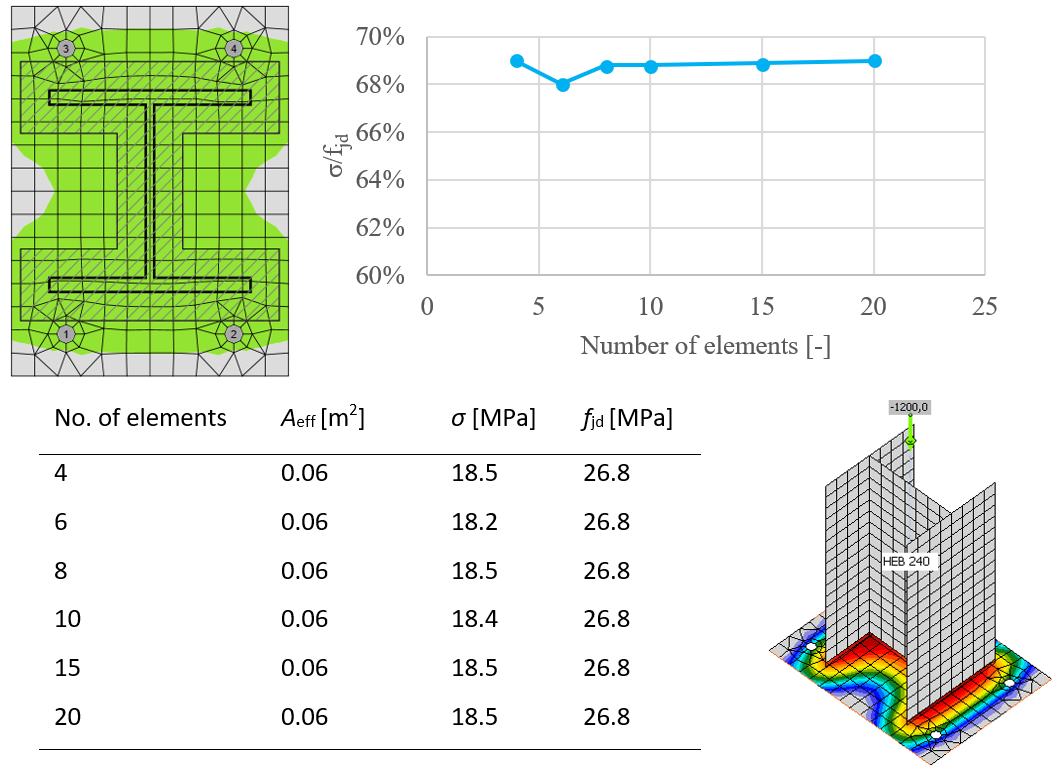
Influence of number of elements on prediction of resistance of concrete in compression in case of pure compression

The influence of the number of elements on the prediction of resistance of concrete in compression in case of compression and bending
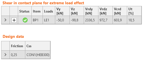
Shear in concrete block
Shear in the concrete block can be transferred via one of the three means:
- Friction
\( Ut = \frac{V}{V_{Rd}} \)
Vrd = N Cf - Shear lug
\( Ut = \max \left ( \frac{V_y}{V_{Rd,y}}, \, \frac{V_z}{V_{Rd,z}}, \, \frac{V}{V_{c,Rd}} \right ) \) \(V_{Rd,y} = \frac{A_{Vy} f_y}{\sqrt{3} \gamma_{M0}} \)
\( V_{Rd,z} = \frac{A_{Vz} f_y}{\sqrt{3} \gamma_{M0}} \)
\( V_{c,Rd} = A \sigma_{Rd,max} \)
Shear iron and welds are also checked by FEM. - Anchors
Check is provided according to ETAG 001 – Annex C
where:
- AV,y, AV,z – shear areas of shear iron cross-section in the direction of axes y and z
- fy – yield strength
- γM0 – safety factor
- Vy – shear force component in the base plate plane in y-direction
- Vz – shear force component in the base plate plane in z-direction
- V – shear force (vector sum of both shear forces components)
- N – force perpendicular to the base plate
- Cf – friction coefficient between steel and concrete/grout; editable in Code setup
- A = l b – projected area of the shear lug excluding the portion above concrete surface
- l – length of the shear lug excluding the portion above concrete surface
- b – projected width of the shear lug in the direction of the shear load
- σRd,max = k1 v' fcd – maximum stress which can be applied at the edges of the node
- k1 = 1 – factor (EN 1992-1-1 – Equation (6.60))
- v' = 1 – fck / 250– factor (EN 1992-1-1 – Equation (6.57N))
- \( f_{cd} = \alpha_{cc} \frac{f_{ck}} {\gamma_c} \) – design compressive strength of concrete
- αcc – coefficient for long term effects on compressive strength of concrete
- fck – characteristic compressive strength of concrete
- γc – safety factor for concrete