
BIM link Connection to Detail - Eccentrically loaded anchoring
1 New project
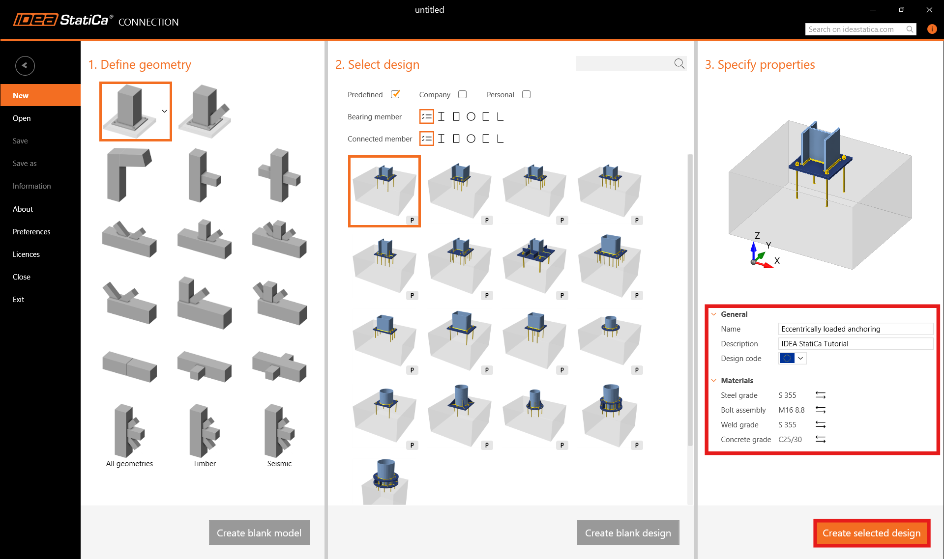
Run the IDEA StatiCa Connection. Everything starts on the Steel card.

Keep default settings for anchoring topology and step into the app.
2 Design
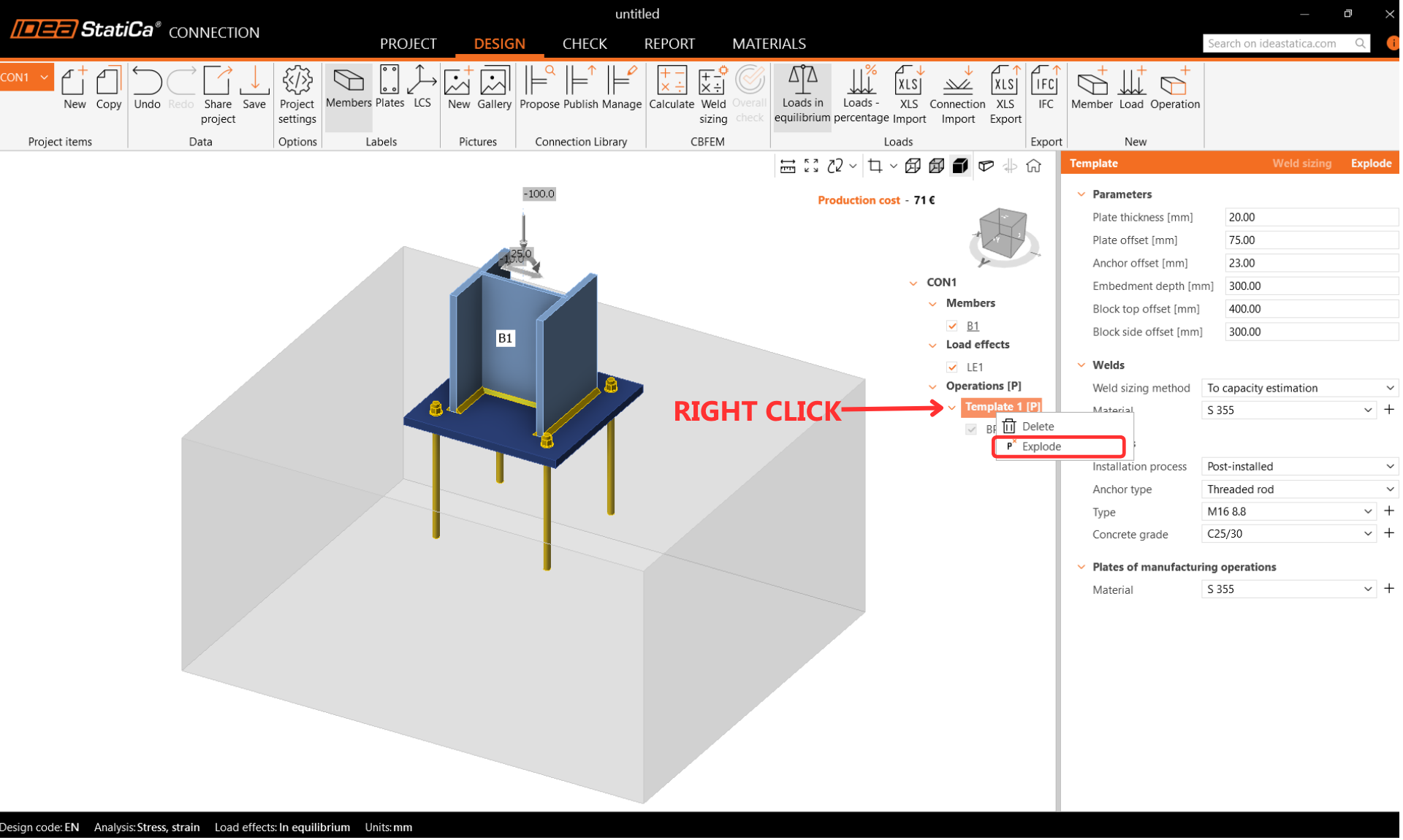
After creating the solution from the template, to move the footing to the edge, we have to explode the template to separate operations.
Let's adjust the baseplate and set The Shear Force transfer as Friction.
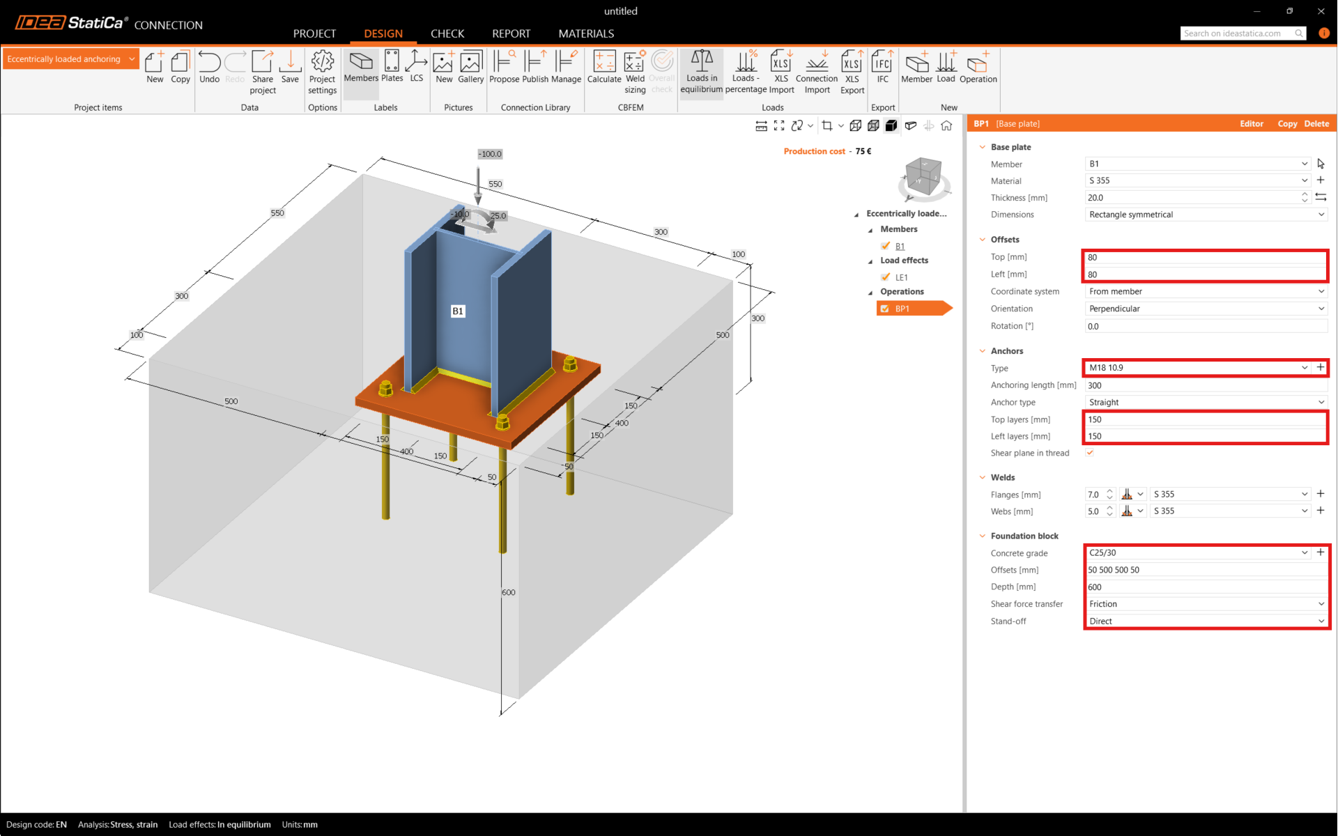
Note: Since the release of version 24.1, IDEA StatiCa Detail has been out of BETA for 3D anchoring design. With this new version, shear can be transferred through anchors, shear lugs, and friction, too.
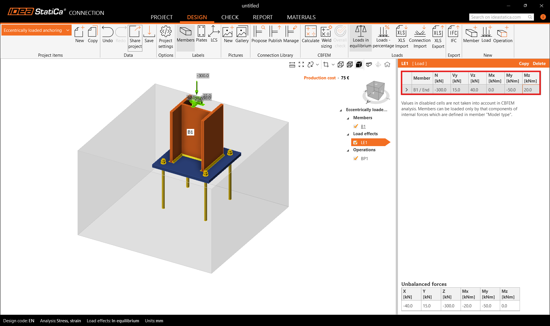
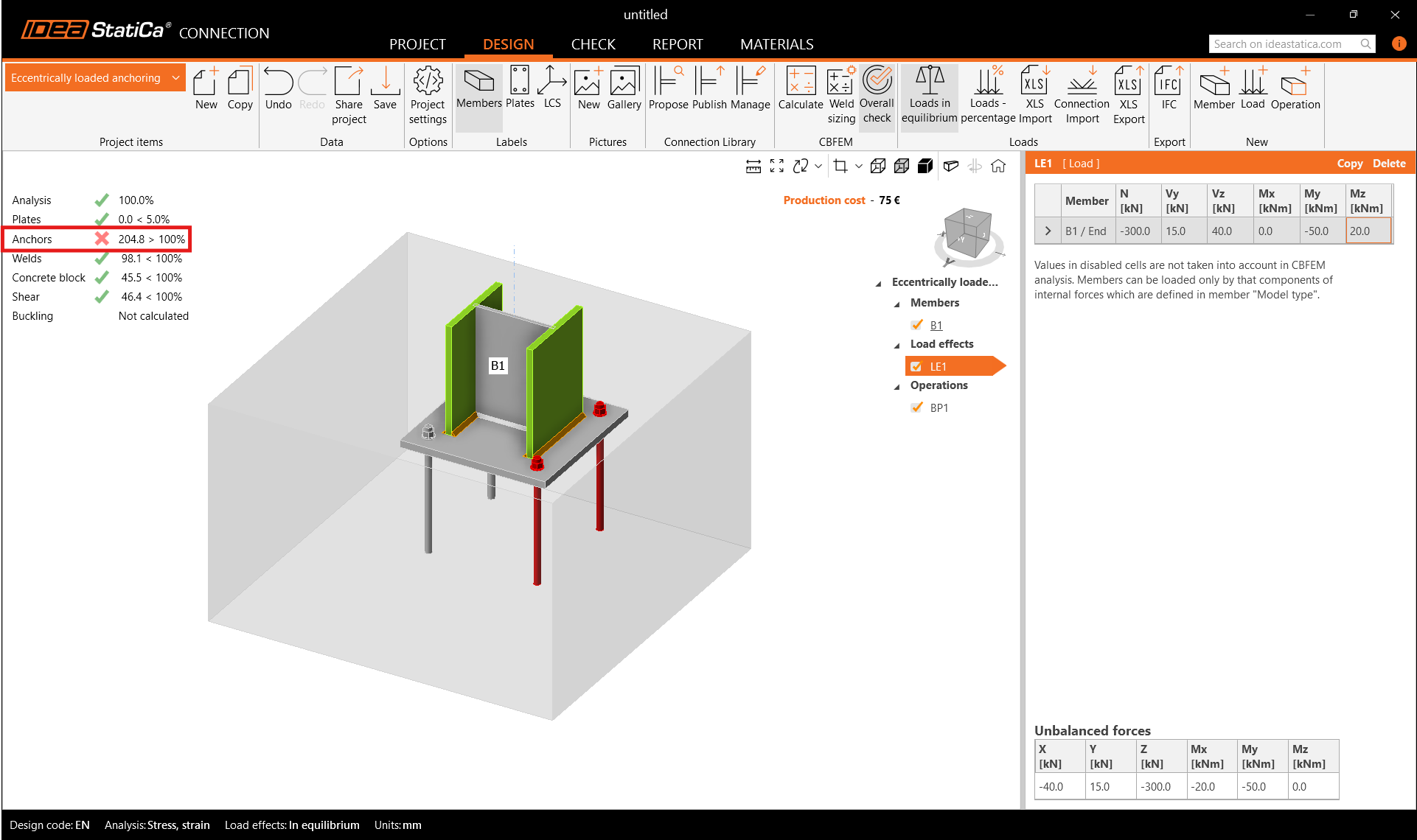
Input the internal forces for biaxially loaded anchoring. The internal forces cause compression stress on the contact between the ground and the concrete block. By default, the concrete block is assumed to be cracked.
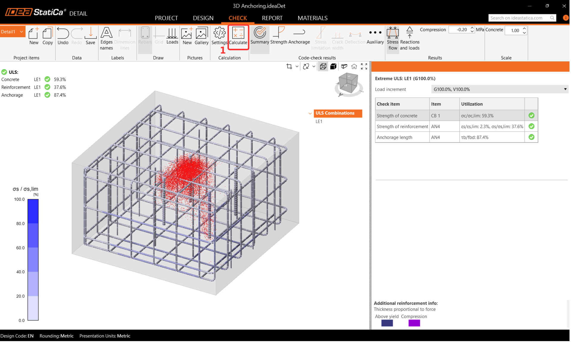
3 Check
Move to card, Check and Calculate. The code check proves the failure mode on the anchors. Let's explore more in detail about it.
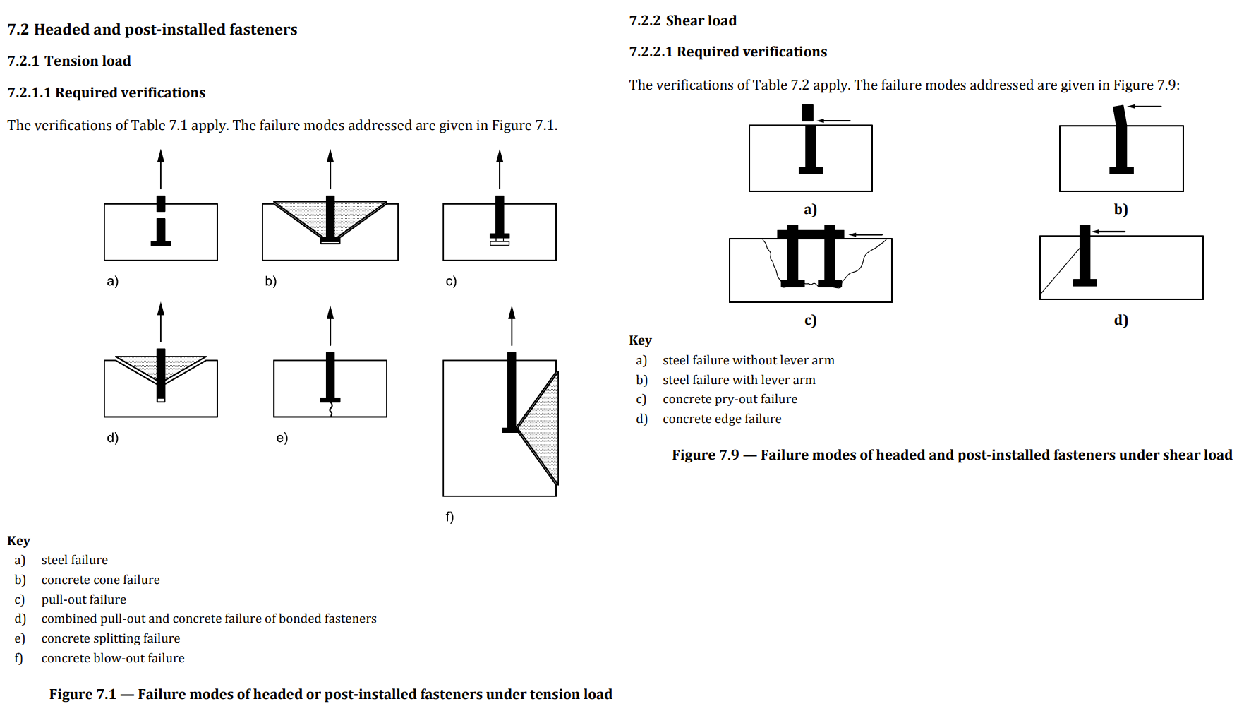
Let's explore the potential failures for tension, shear, and mutual interaction according to EN 1992-4.
Please review the Detailed Check of the Anchors, as it reveals a nonconformity on the first page. This will inform you of the code-checks that you need to perform manually or using other methods, as they are not included in IDEA StatiCa Connection. It is recommended that you take the necessary actions to address this issue.
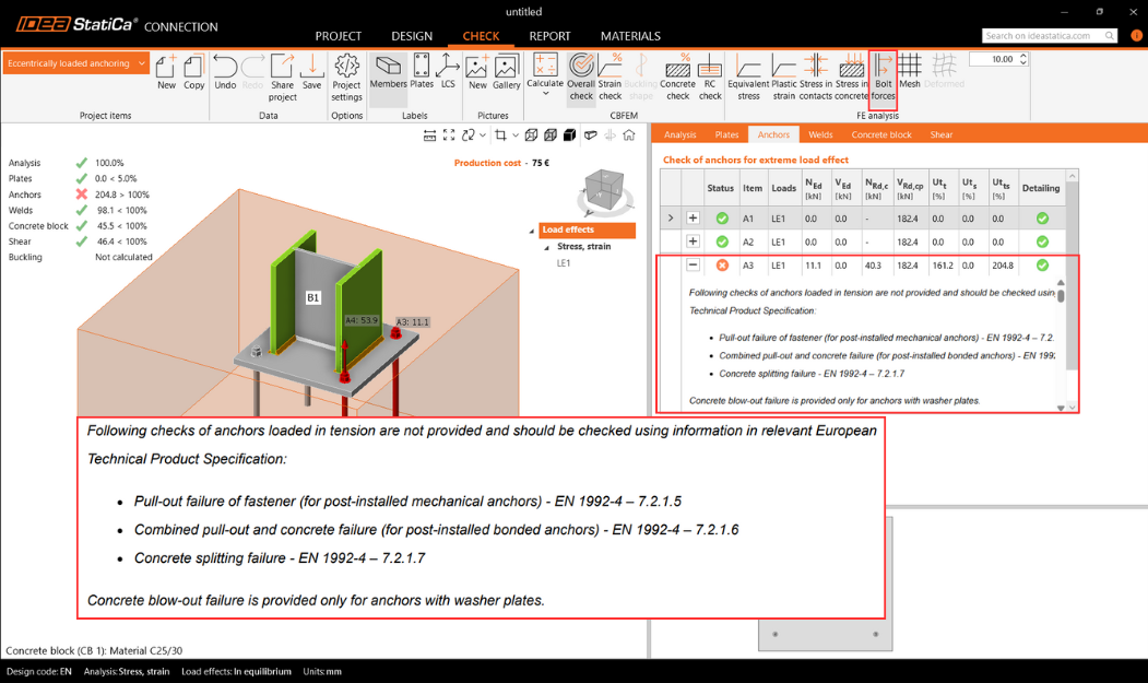
Due to the failure of Anchor Check:
- The problem is caused by the Concrete breakout resistance of anchors in tension and shear
- This issue can be easily solved in IDEA StatiCa Detail, powered by the 3D CSFM method. It helps you overcome the model of plain concrete cracked blocks in IDEA StatiCa Connection.
4 Export
The in-house developed application IDEA StatiCa Connection now features a powerful BIM link into Detail, allowing for the design and check of reinforced concrete blocks with multiple combinations.
Prerequisites for export:
- The model has to be pre-calculated and the results included
Go to the card Check -> RC check -> Save.
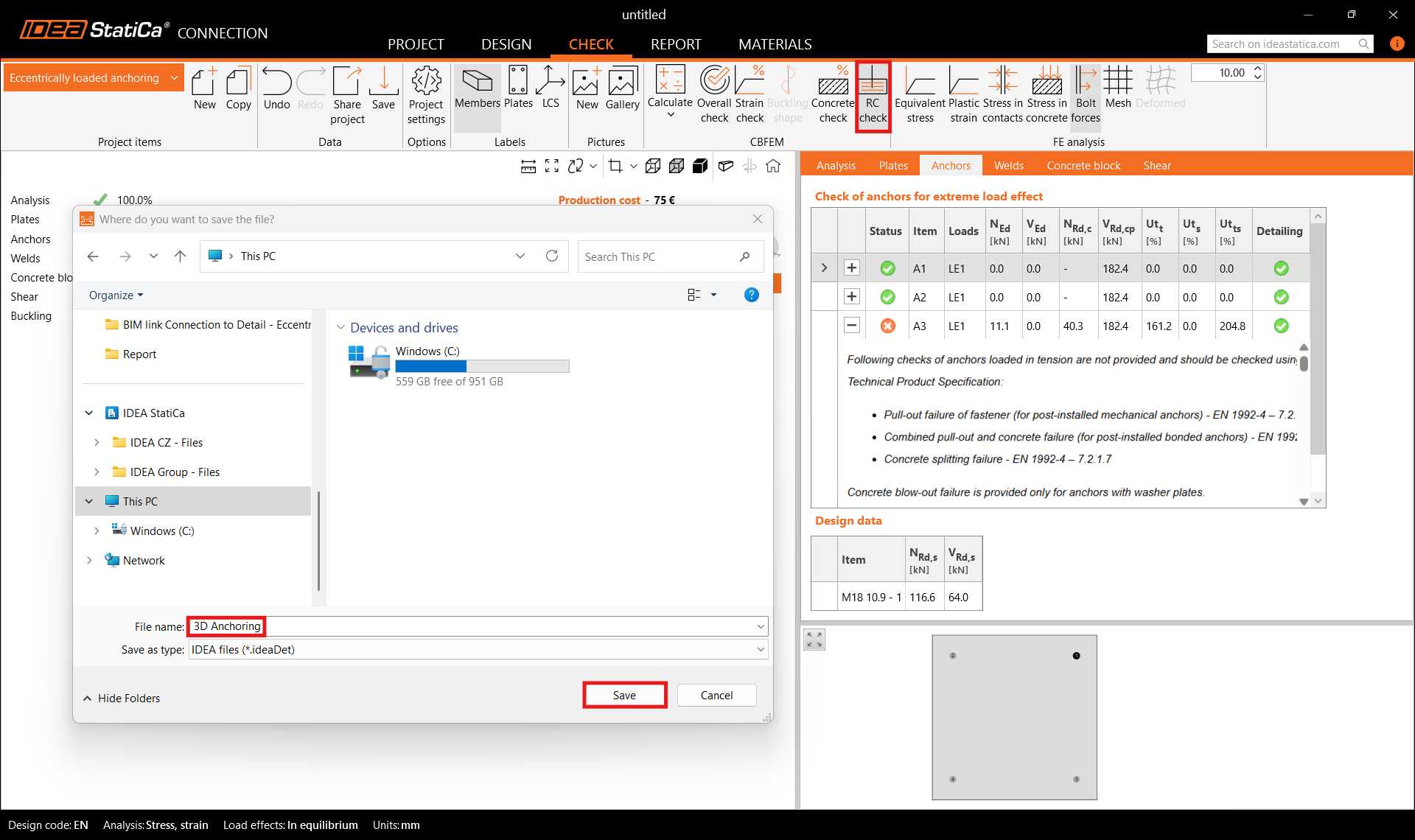
The export is allowed only for anchoring topology. The export allows the transfer of:
- The concrete block
- Anchors
- The base plate
- Loads
Additional information and parameters that are set according to the corresponding settings in the Connection:
- Shear transfer (through Anchors, Shear lugs, and Friction)
- Material
- Anchorage Type: Post installed (Adhesive) /Cast-in place
- Anchorage type at the end: Washer/Straight/Hook/Headed stud
- Friction coefficient
5 Design
This section will allow you to modify Members, Supports, Loads&Combinations, and Rebar assembly.
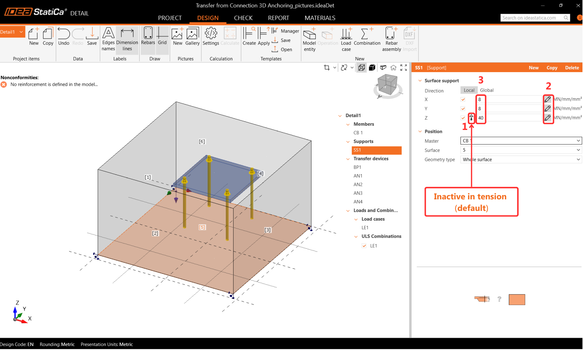
Support
The ground has some stiffness, which should be considered for precise design. The Surface Support enables stiffness in all three directions and is set as default inactive in tension (boundary nonlinearity).
- Please be cautious while making assumptions about boundary conditions. In the case of nonlinearity, if the moments are quite high, the concrete block's support in tension may turn over during analysis, causing large rotations. This may lead to a divergent model due to the flexible body motion.
Transfer devices
The anchors are taken over from IDEA StatiCa Connection. Two types of anchors can be selected.
Cast-in-place anchors:
- Pre-installed anchors with the same properties in bond as the reinforcement bars
Post-installed (Adhesive) anchors:
- Post-installed (chemical anchors) with the option to customise your bond strength based on the actual bond strength.
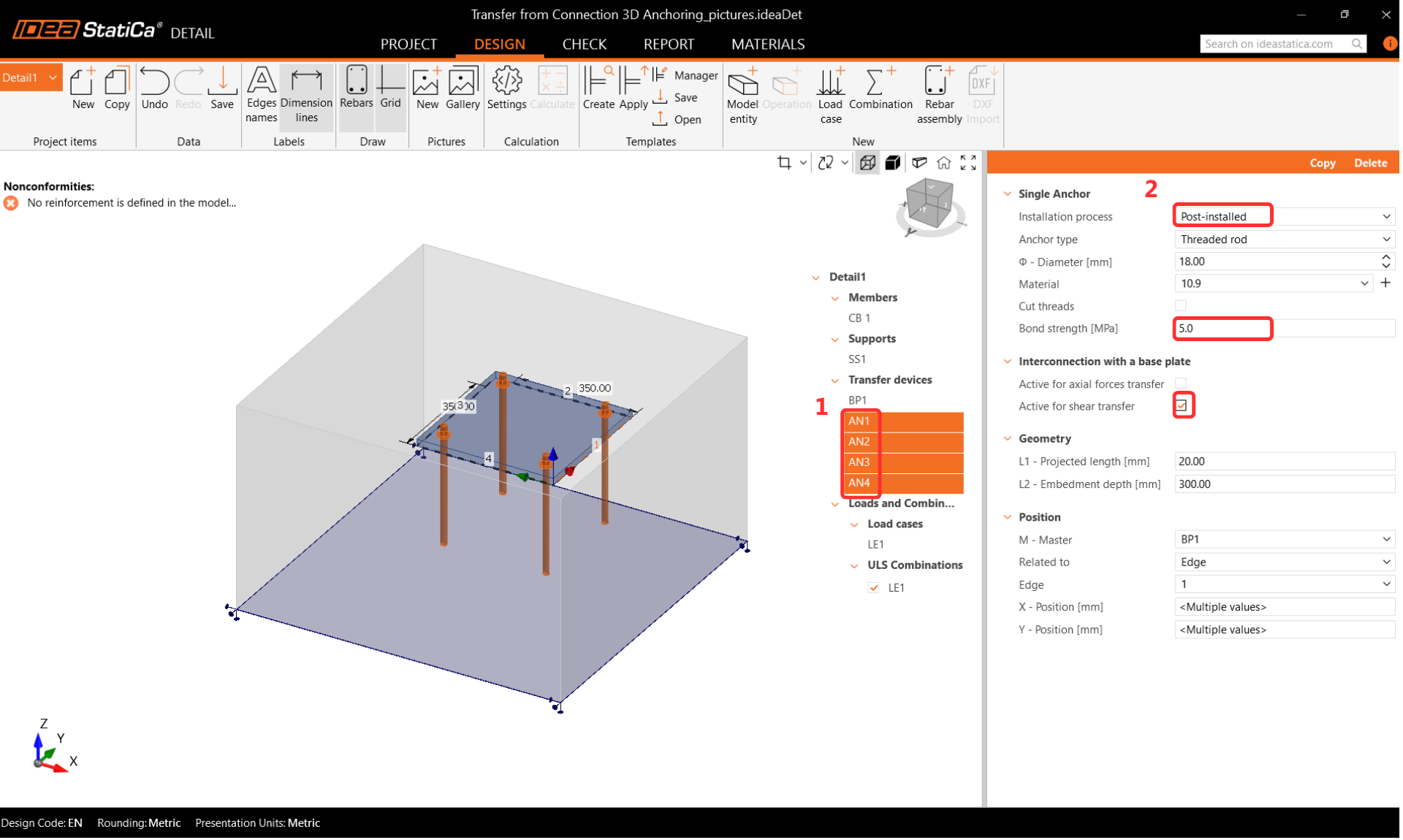
Pay attention to the correct setting of the Interconnection with a base plate. In the case of importing the footing from the Connection application, the Transfer of axial forces should be OFF, and the Transfer of shear should be ON. The reason is that the anchors are loaded directly by forces. You can read more about this here.
If you were to design a footing from scratch in the Detail application, both options would be ON. When transferring shear through anchors, the user must determine which anchors will bear the shear force and select the corresponding checkbox. This aligns with EN requirements, which specify that shear should only be assigned to anchors effective for the concrete edge failure check.
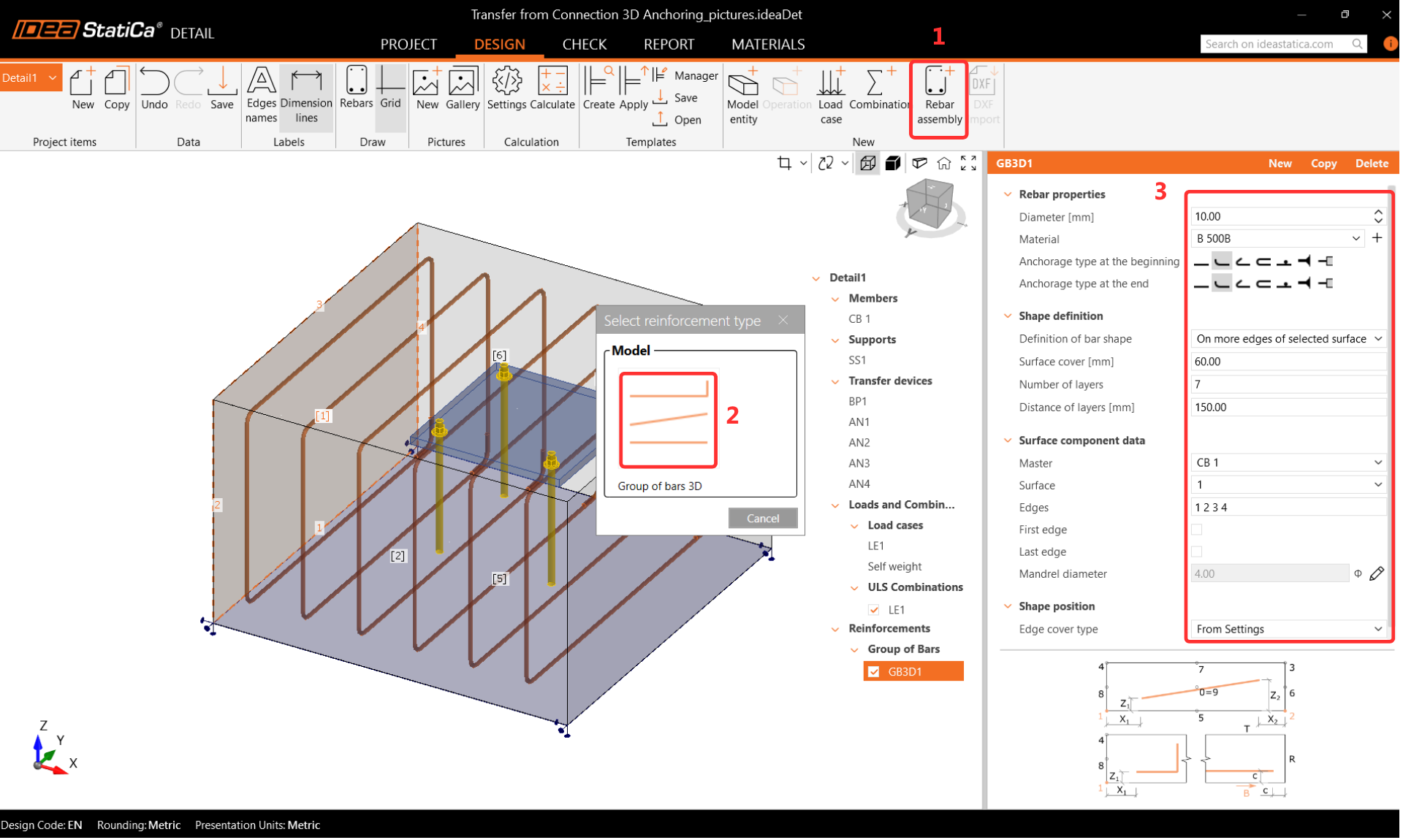
Reinforcements
Set the concrete cover to 40 mm, which will be used as the default value for the reinforcement.
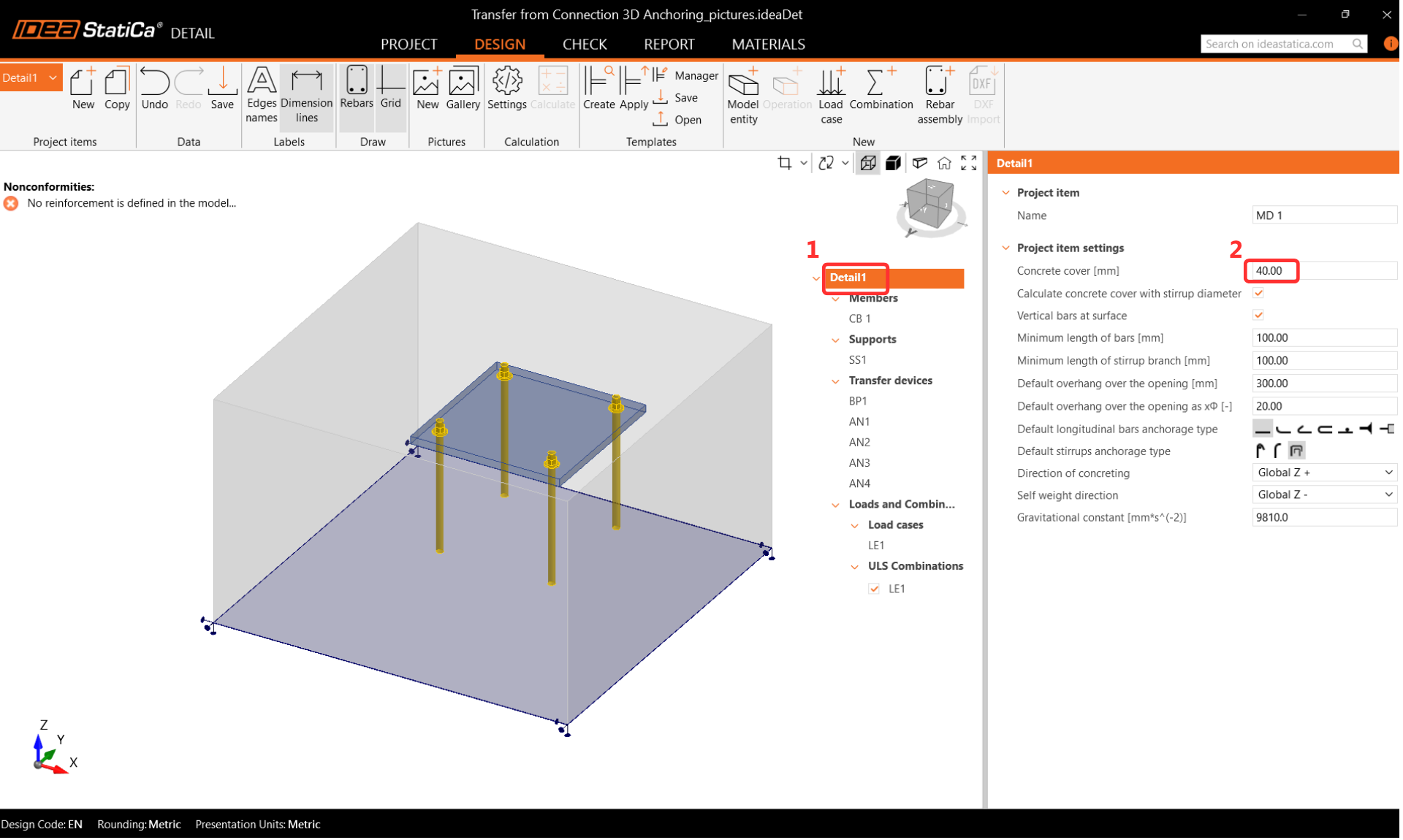
Select the Rebar-Assembly(1)-->Group of the bars 3D(2) and filling out the Diameter, Properties and Geometry(3).
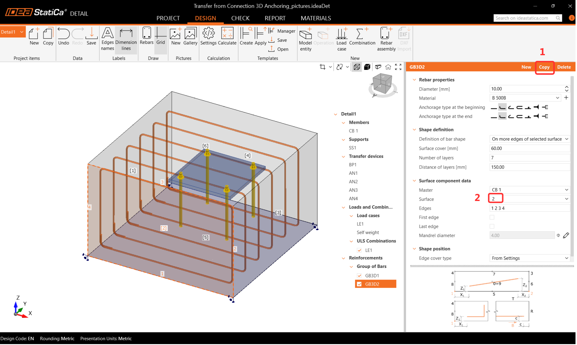
Copy the operation and change the Surface. All the other options are retained.
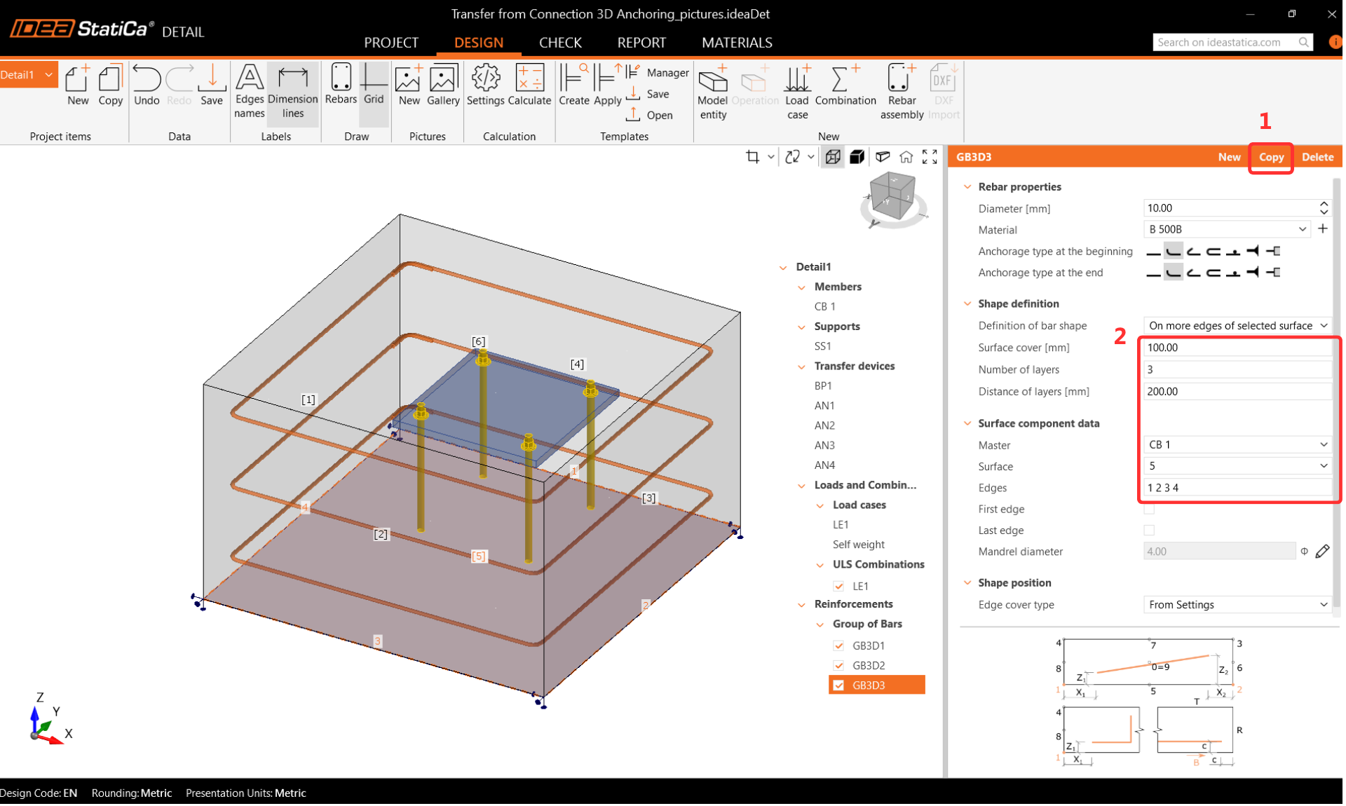
Copy the operation and change the options below.
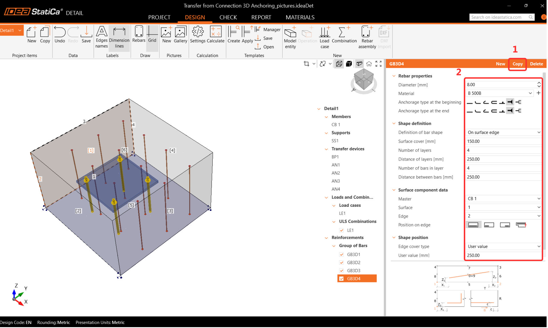
Copy the operation and change the options below.
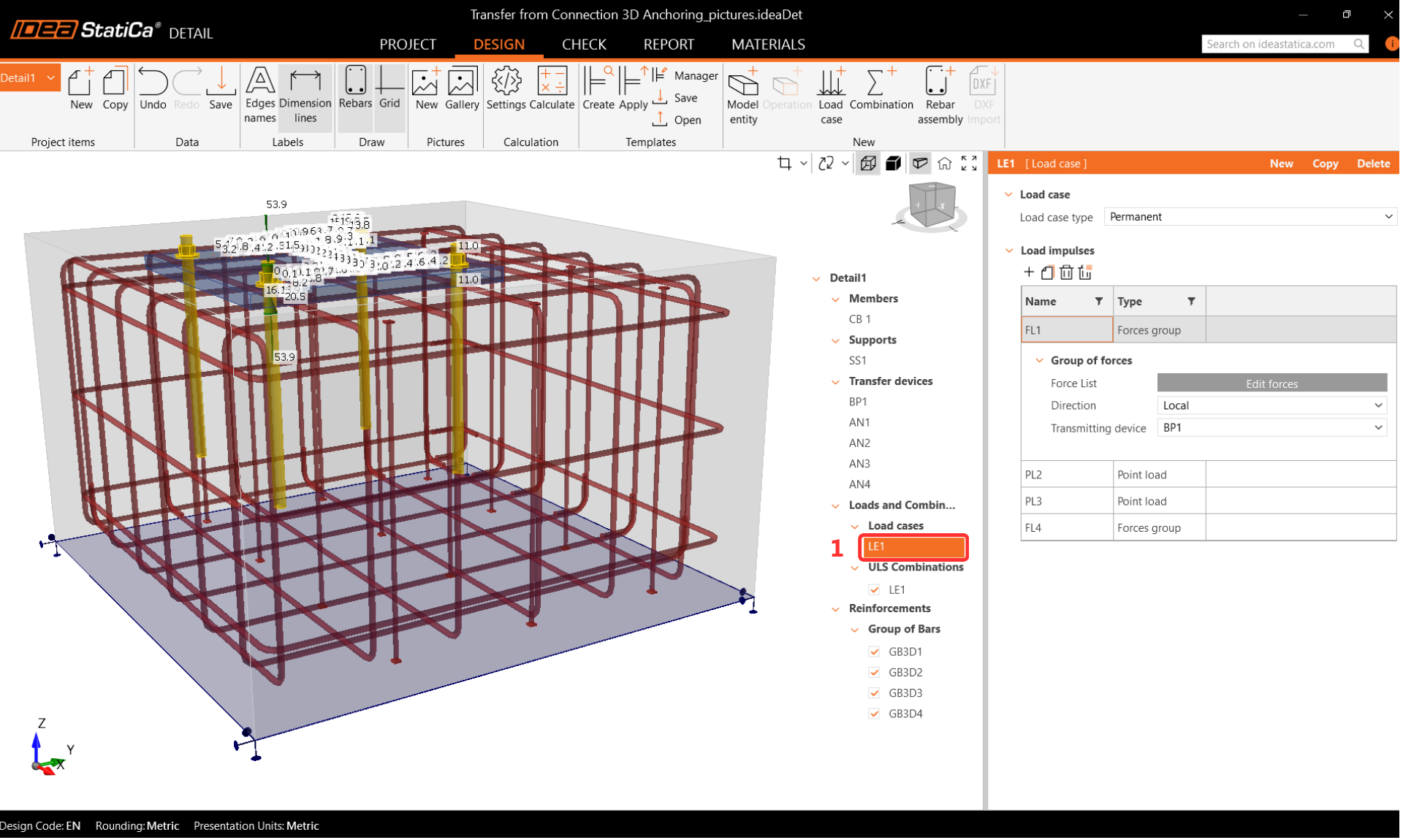
Loads and combinations
Combinations are taken over from IDEA StatiCa Connection. All the consequences of import are mentioned
in detail in - Import of anchoring from Connection to Detail.
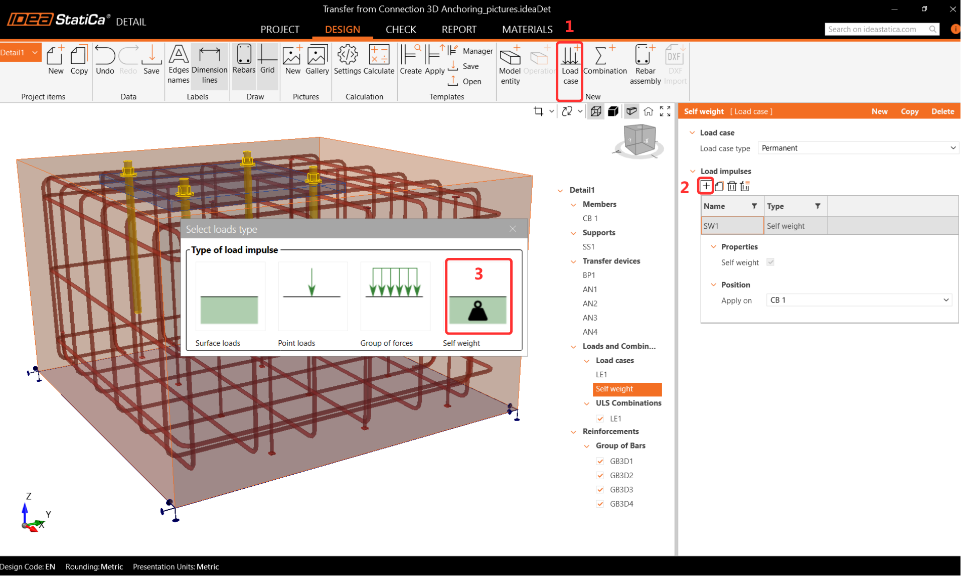
Let's create the Self-weight:
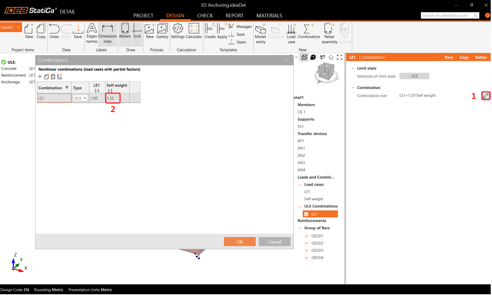
Create a combination with Self-weight, and add the coefficient for self-weight = 1.35 according to the codes
EN 1991-1-1
6 Check
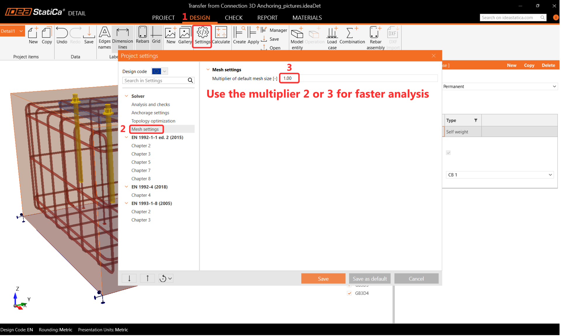
Before running the analysis, we highly recommend changing the mesh multiplier to two or three in order to speed up the calculation. This step is not mandatory, but it can reduce computational time and help detect any divergence issues. If everything works smoothly and no problems arise, you can switch back to a multiplier of one.
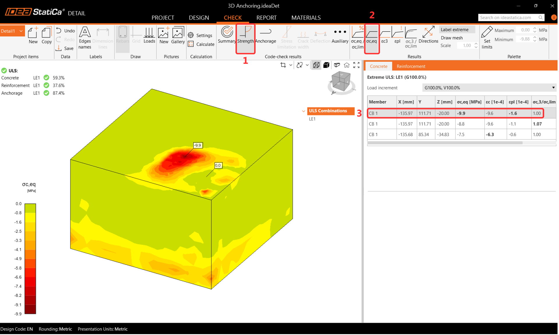
Results
Equivalent Principal Stress
The equivalent principal stress (EPS) in concrete is determined based on the volume behaviour of the concrete block. The areas that experience the highest load are identified and highlighted. In order to gain insight into the confinement in contrast with uniaxial compression, the equivalent stress is calculated using the kappa factor. More information about equivalent principal stress is enclosed in this article of the theoretical background.
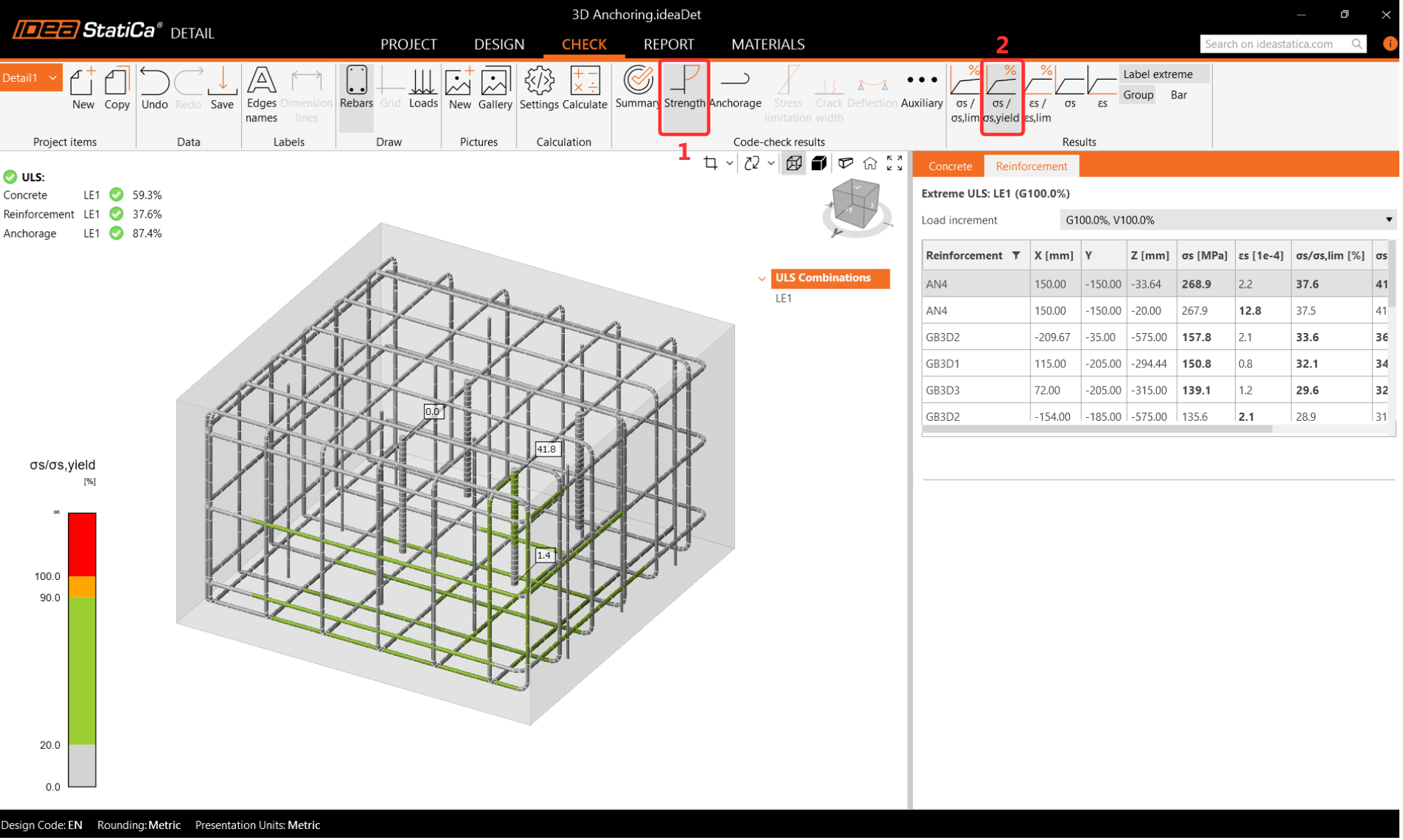
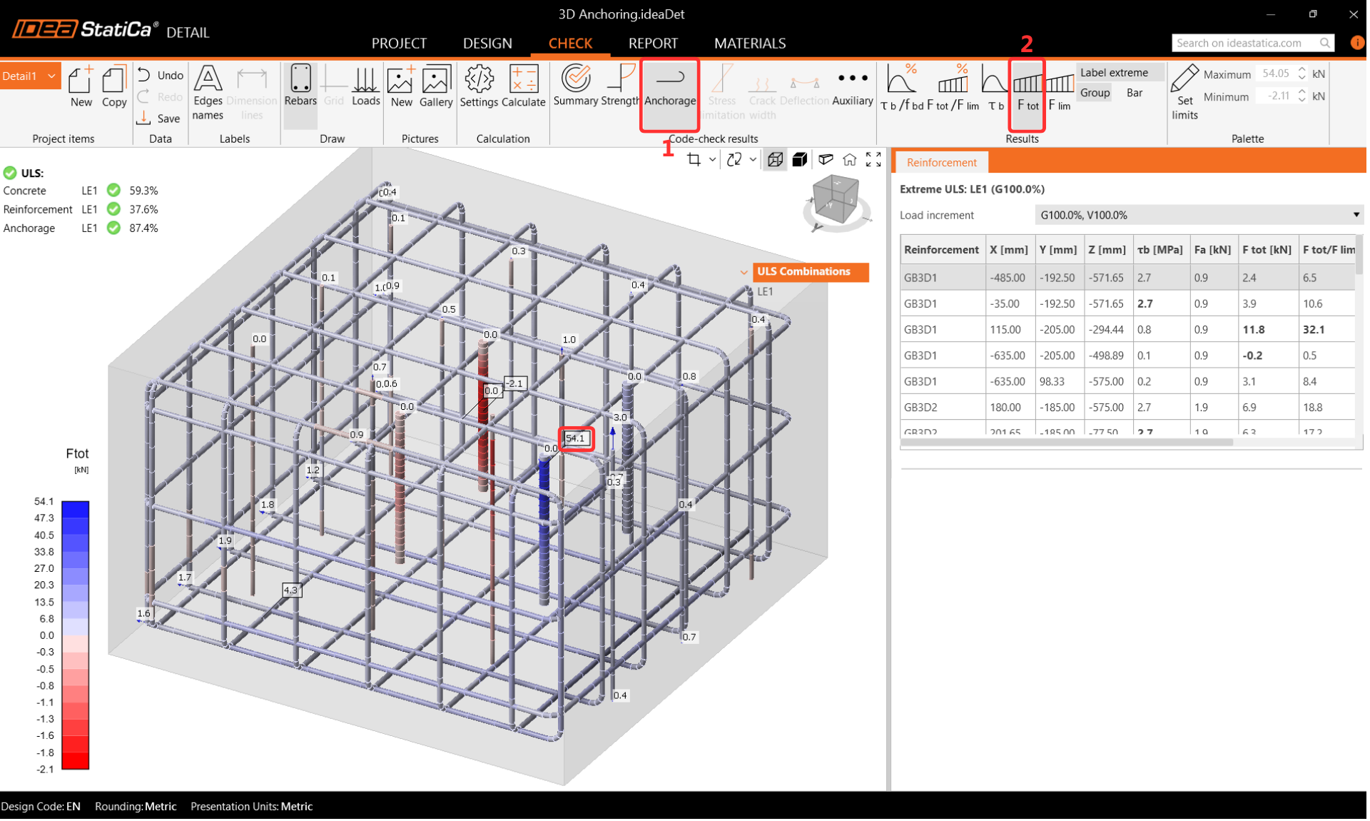
Stress in rebars
During the Reinforcement Check, it is critical to note that the anchor close to the corner is maximally utilised.
When displaying the utilisation of reinforcement, the user can clearly see which reinforcement contributes to transferring the load and preventing the concrete cone failure.
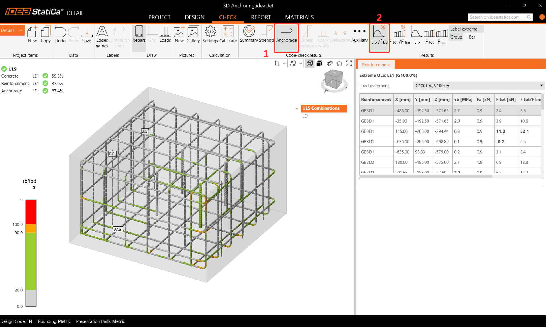
Anchorage
Double-check the Anchorage settings and activate the Total Force in Anchors. The forces in the anchors may vary slightly due to the different calculation approaches regarding the concrete block. The differences are not significant, though.
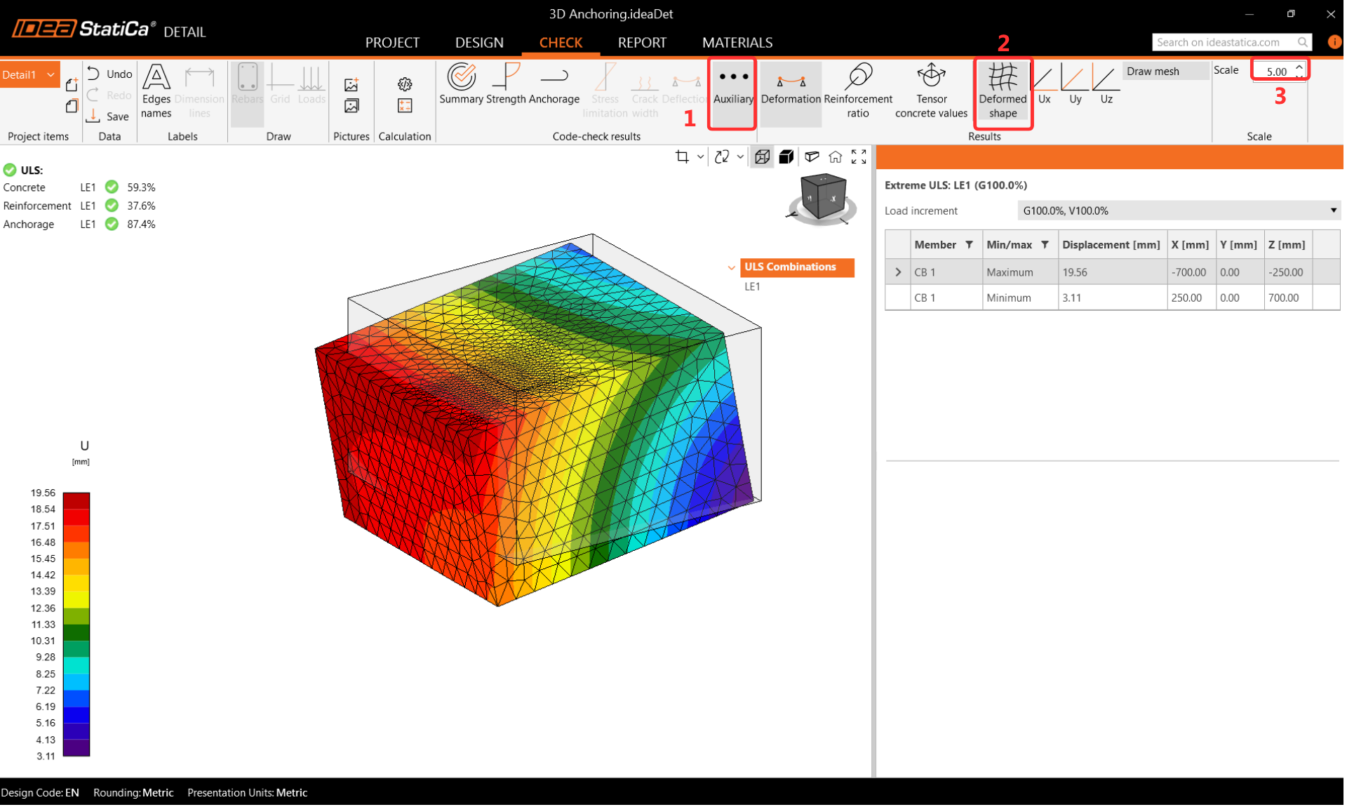
Deformations
Move to Auxiliary and turn on the Deformation.
It is not necessary to perform a deformation check for ULS, but it is highly recommended to check the deformation after analysis to ensure that the model is not experiencing large deformation, large rotation or any finite element is damaged. This will provide an overview of the analysis results and help identify any issues that may have arisen during the analysis.
7 Report
At last, go to the Report Preview/Print. IDEA StatiCa offers a fully customizable report to print out or save in an editable format.
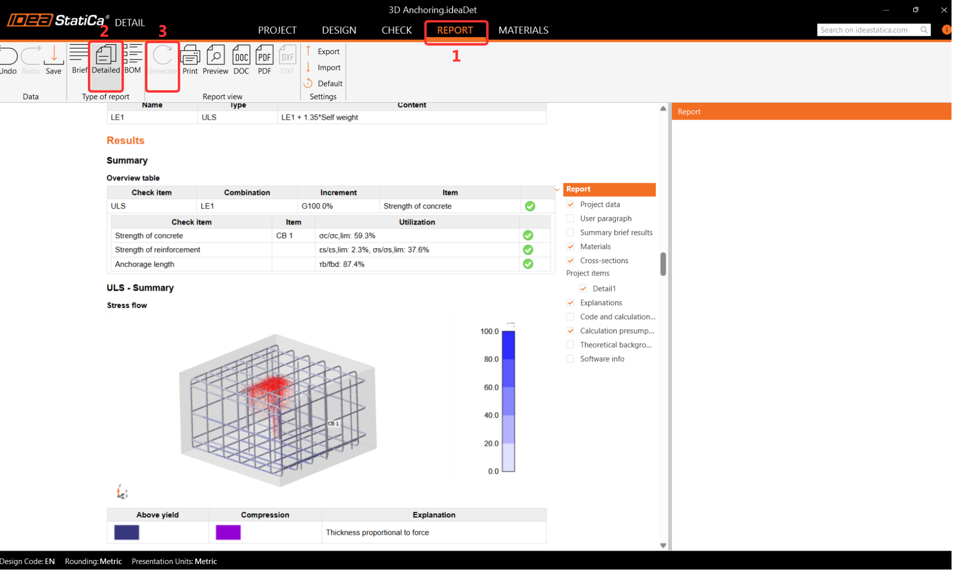
You have checked the whole connection design according to the codes EN 1993-1-8 and EN 1992-4. The steel part was checked in IDEA StatiCa Connection, and the concrete block was code-checked in IDEA StatiCa Connection and Detail.