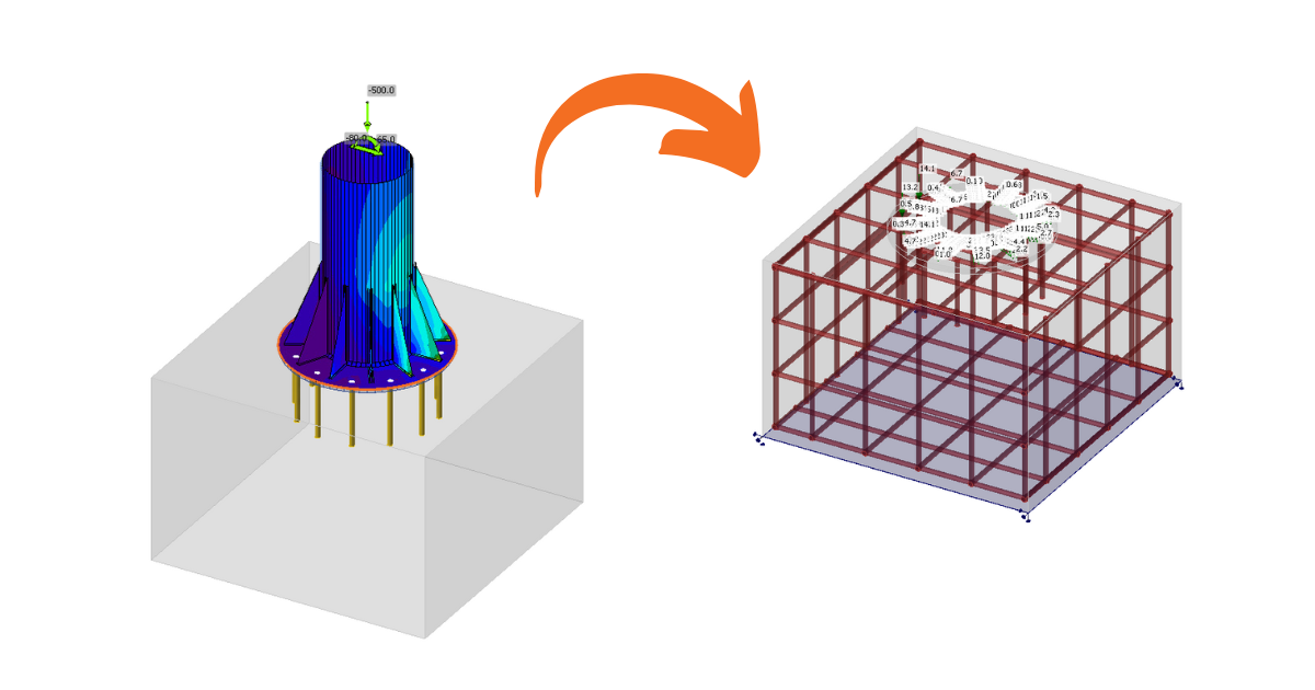
Anchoring in a plain concrete block can be modeled and code-checked in IDEA StatiCa Connection. For certain cases, such as anchorage near the edge, the design is insufficient due to possible failure modes, and additional reinforcement is required. Although, this capability isn't available within the Connection app, it is possible to continue directly into the Detail application.
3D Detail is focused on solving anchoring into concrete blocks and analysis of both the anchoring elements and the concrete block itself. Moreover, a direct link is implemented between the Connection and Detail applications to simplify the process. Connection users who design anchoring according to Eurocode or AISC can import their model from Connection to the advanced 3D Detail by one button click.
- Import is allowed just for anchoring. If there is no concrete block in the Connection model, the export to Detail is disabled ("RC check").
- The model in Connection has to be calculated. If results are not available, the export icon ("RC check") is disabled. For export functionality, it is also necessary to have valid licenses for concrete applications. Otherwise, the export option will be disabled again.
- Only one concrete block for the import/export is allowed.
- Some anchor types are not supported for import, and we also do not recommend exporting so-called edge anchoring. A detailed breakdown of the limitations is provided in the article: Known Limitations for 3D Detail
The connection is imported, including
- The concrete block
- Anchors
- The base plates
- Loads
Additional information and parameters that are set according to the corresponding settings in the Connection:
- Shear transfer (through Anchors, Shear lugs, and Friction)
- Material
- Anchorage Type
- Anchorage type at the end
- Friction coefficient
The possible configurations and types of anchors that can be exported can be found in the following articles:
Export from Connection to Detail step by step
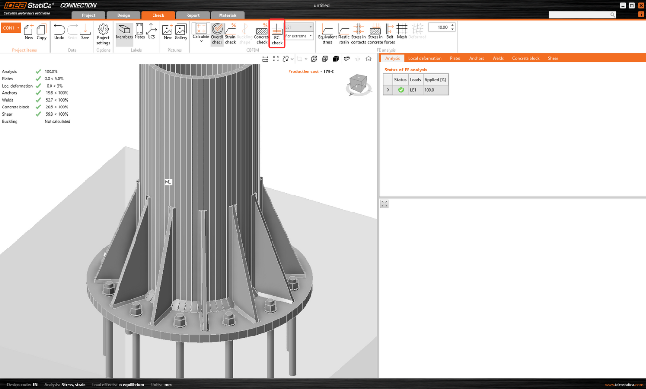
First, create a model of anchoring in Connection according to Eurocode/AISC and click the Calculate button.
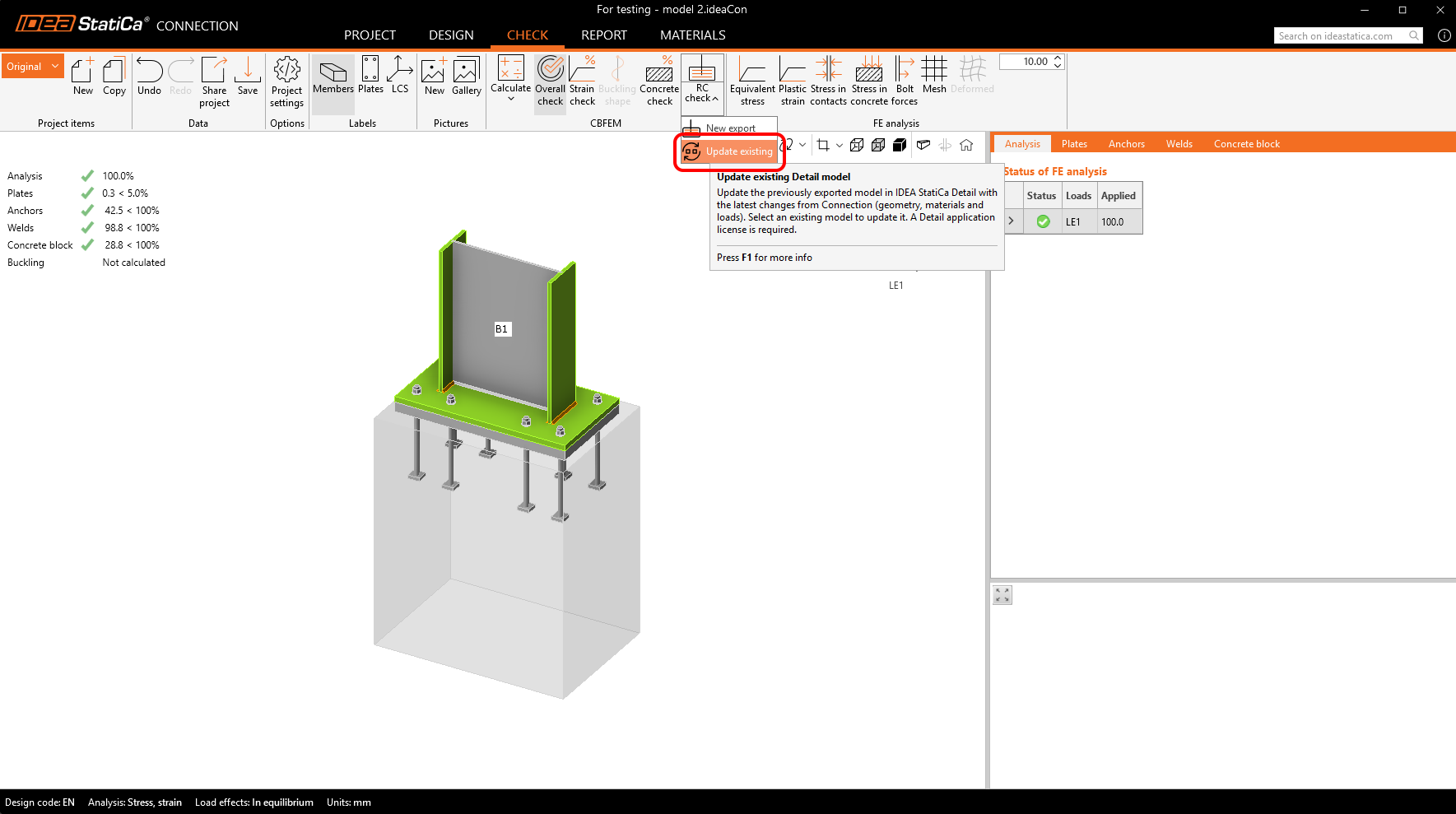
When results exist, export of footing is enabled. By clicking the button "RC Check" in the ribbon, a dialog asking for the location and the name of the newly created Detail file appears.
After a successful export, the project in Detail is created. The geometry of the concrete block and the base plate, the position and properties of anchors, and the load are automatically transferred to Detail. Surface support placed at the bottom surface of the concrete block is automatically created.
Note: It is only necessary to check the settings in the Z direction. (For foundation footings, we use compression-only with the soil stiffness setting; for a continuing structure, we can also enable tension support).
The most tricky part of this process is the import of the load. For every calculated load effect in Connection, the corresponding load case and the ULS combination are automatically created in Detail.
- The base plate is loaded by forces in welds, which are modeled as a Group of forces. For the loading of the base plate itself, the imported loading is represented by a group of forces following the stresses in welds between the base plate and steel members in the Connection model.
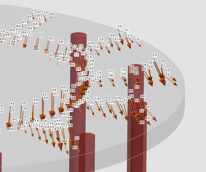
- Anchors are modeled and loaded independently from the base plate, and they are axially loaded by point loads. The loading of anchors is represented in the scene by a double of arrows in opposite directions. One arrow represents the tension force acting only on the top of the anchor. The other one represents the compression force acting on the base plate.
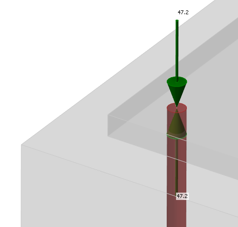
The Checkbox "Transfer of axial forces" is unticked by default as the anchors are loaded by forces directly.
Note: The following figure does not apply to cast-in plates, where axial force transfer is correctly checked after export. The reason for this can be found in the Theoretical Background.
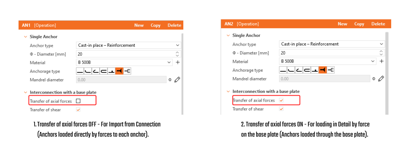
- Shear is transferred according to the setting in Connection by one of the options – anchors, shear lugs, or friction. If the shear force is transferred by anchors, you can turn off specific anchors by unticking the checkbox "Transfer of shear".
- If friction or shear lugs are set, shear in the anchors is never considered in the model. (Even if the checkbox is selected.)
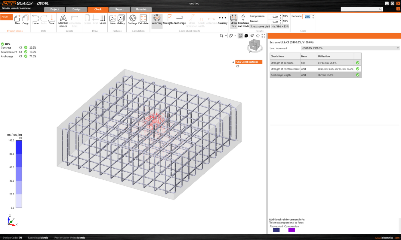
Then just add the required reinforcement using the tools mentioned above and calculate the model. Don't forget set the Design Bond strength for adhesive(post-installed) anchors according to the manufacturer’s parameters.
It is also a good idea to check that the specified load will not overturn the concrete block. Overturning can be prevented by self-weight or sufficient compressive normal force. If the resultant vertical force is positive (the block will be lifted off the support), the calculation will also fail.
Since the concrete does not act in tension, the cover between the bottom reinforcement and the support will be peeled off.
A thorough explanation of imported forces acting on the base plate or anchors, which are shown in the figure below can be found in the Theoretical background.
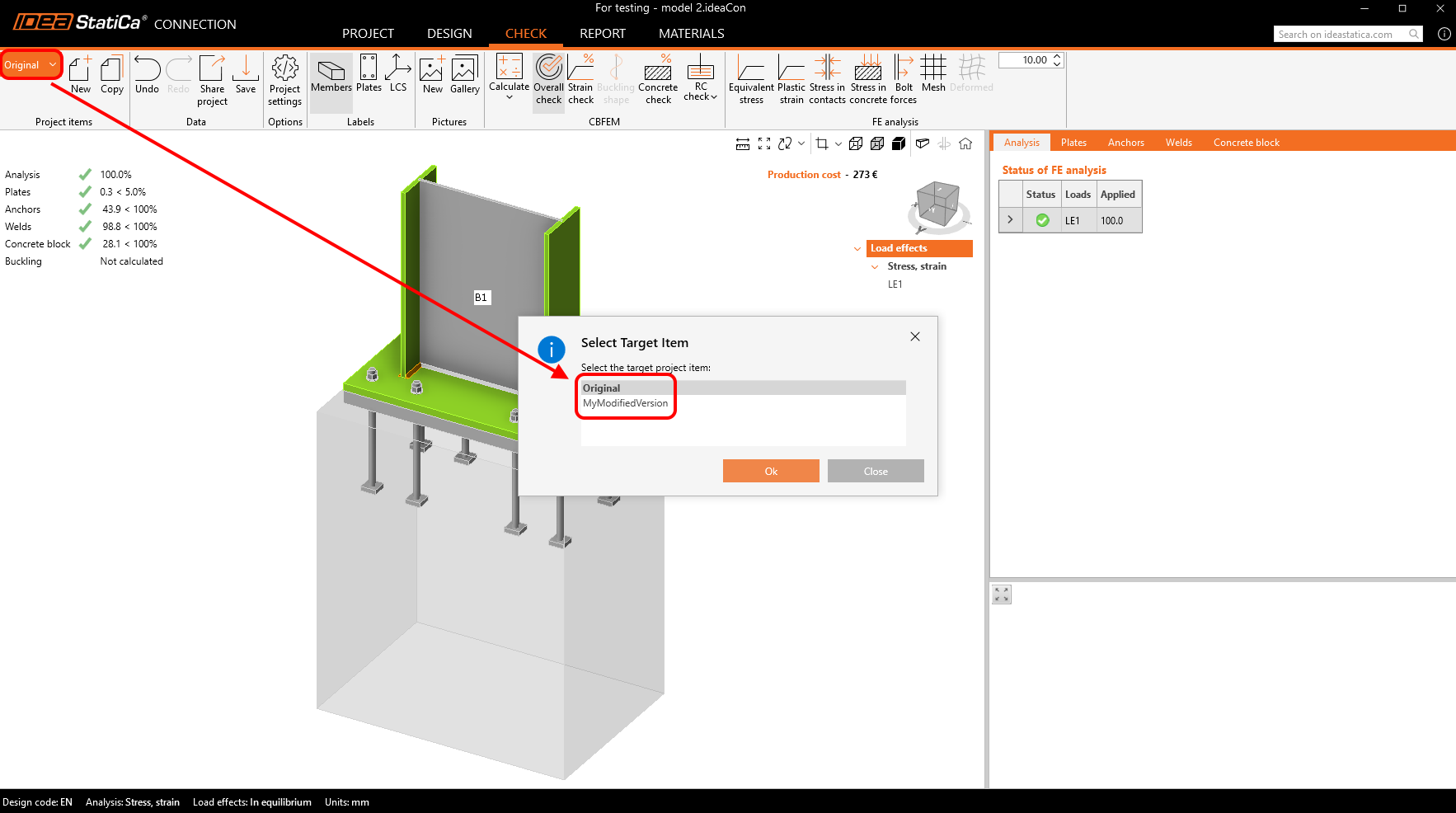
One-way sync from Connection to Detail
The Connection application provides an “Update Existing” function to synchronize a Detail project with the latest Connection data, eliminating the need to recreate the model from scratch.
The update process synchronizes the following data:
- Concrete block: geometry and material
- Base plate / cast-in plate: geometry and material
- Anchors / fasteners: geometry and material
- Load data: load cases, impulses, and combinations
The settings are not imported/synchronized, so code must always be set correctly.
During the update, entities originally created from Connection are handled as follows: existing entities are updated with the new data, entities no longer present in Connection are deleted, and new entities in Connection are added to the Detail project. Entities created directly in Detail remain unchanged, including negative volumes, cuts, boolean operations, reinforcement, plates, anchors, and load cases.
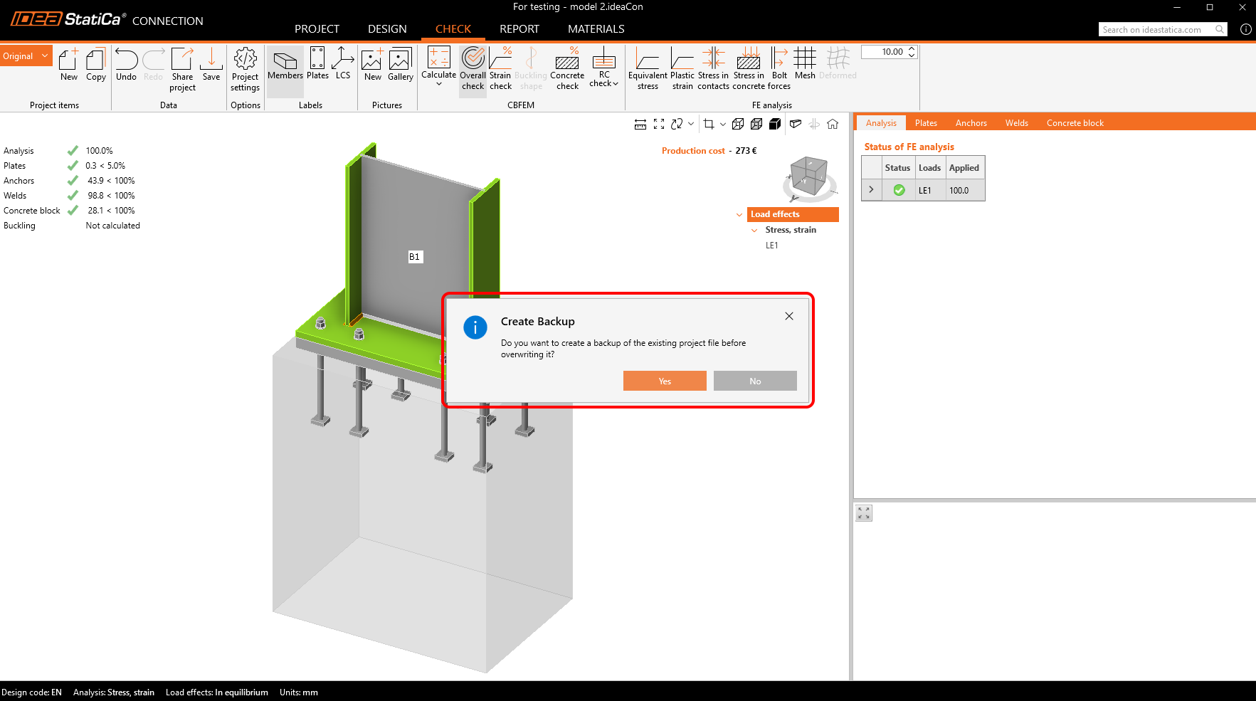
Before updating, the system asks to create a backup, and backups are automatically stored in the same folder to ensure recovery of the previous state.
The workflow supports multiple project items in both Connection and Detail. It is possible to copy a Connection project item to create a variant and then synchronize it with the corresponding Detail project. Updates are also supported for Detail projects containing multiple project items, allowing all relevant data to remain consistent.
Note: Released in IDEA StatiCa version 24.1. for EN. Gradually improved by implementing AISC, adding anchoring-element options, and refining the limitations. This article, including the full functionality, is applicable as of version 26.0. The individual changes can be seen in the release notes.