1 New project
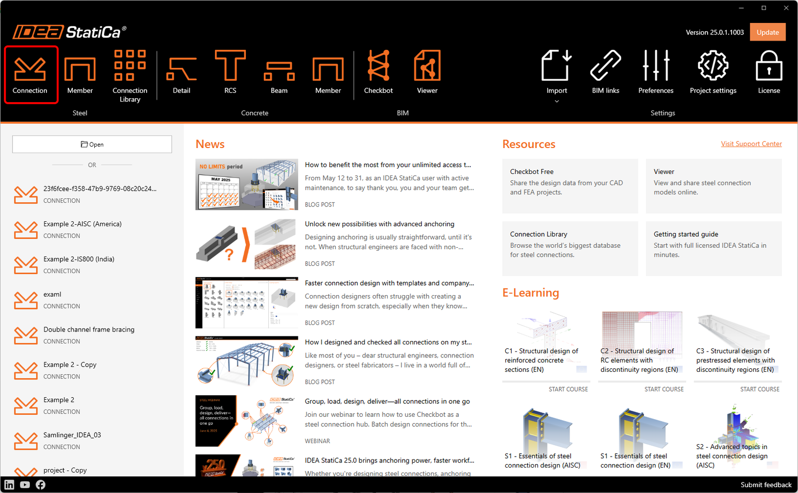
Let’s launch the IDEA StatiCa Connection application (download the newest version). In the main window of IDEA StatiCa Launcher, open the Connection application to define a new project.
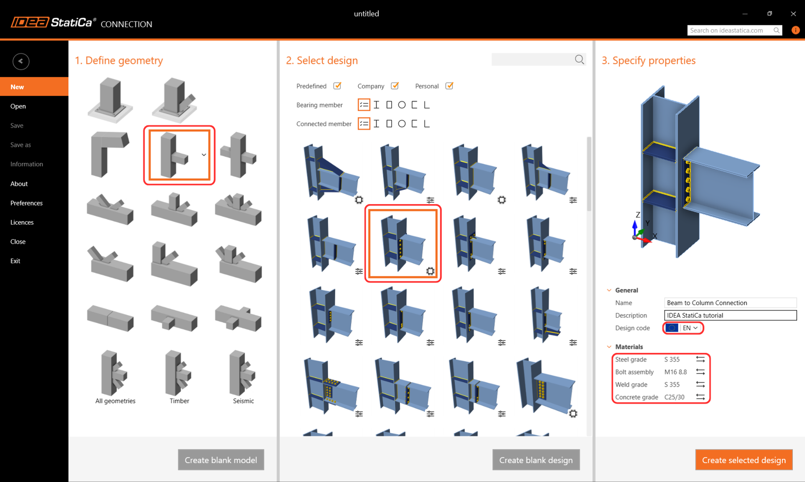
As the first step, you can find your desired connection in the starting templates. Select the shape in 1. Define geometry and the design type in 2. Select design.
In 3. Specify properties, you can name your project, define the materials – steel grade S355 and bolt grade M16 8.8, and the design code – Eurocode (EN). You can change the materials of the created project later, but the design code can not be changed anymore.
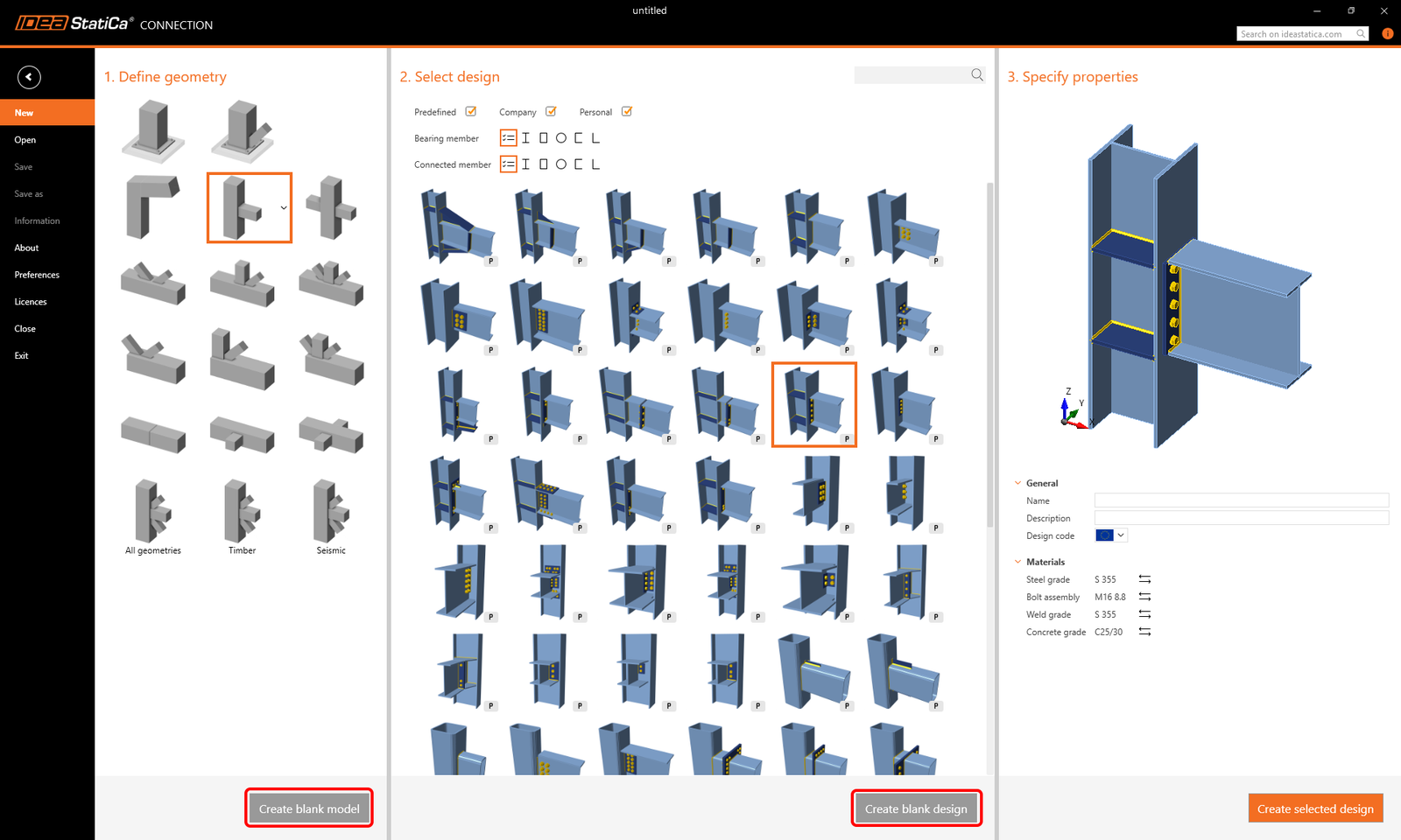
Note: If you don't find a suitable template, you can start with a project with members only by choosing Create blank design or with a completely blank project by choosing Create blank model.
A new project was created based on the selected template. In the top ribbon, you can find different tabs that will lead you through the whole workflow – from Design to the Report. To control the model in the 3D scene, use your middle mouse button, Ctrl key, and the view control icons.
You start in the Design tab, here just follow the "tree of items" in the 3D scene.
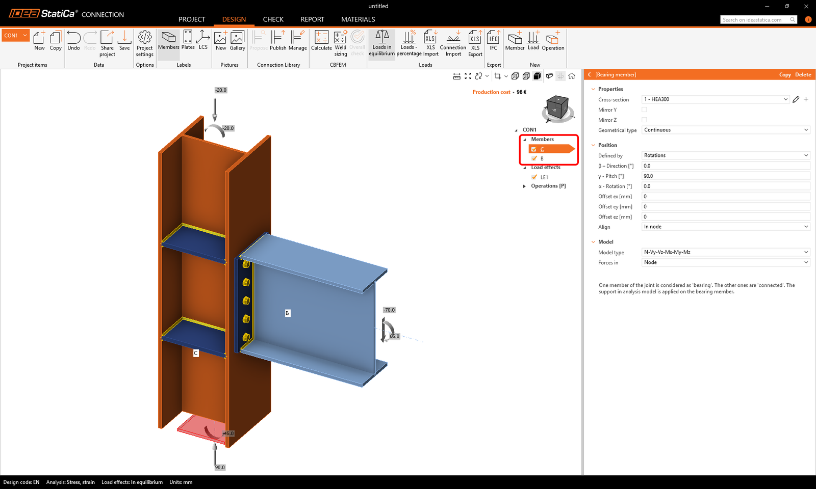
In Members, you can adjust the parameters of the connecting structural members (such as their orientation, cross-section, material, geometrical type, etc.). Leave the parameters set from the template.
- Read more about the Ended and Continuous geometrical type and the bearing member in Equilibrium and supporting member.
- Read more about the Model type in How to model a single bolt connection (Model type).
- Read more about the Forces in option in How to define correct load position (Forces in).
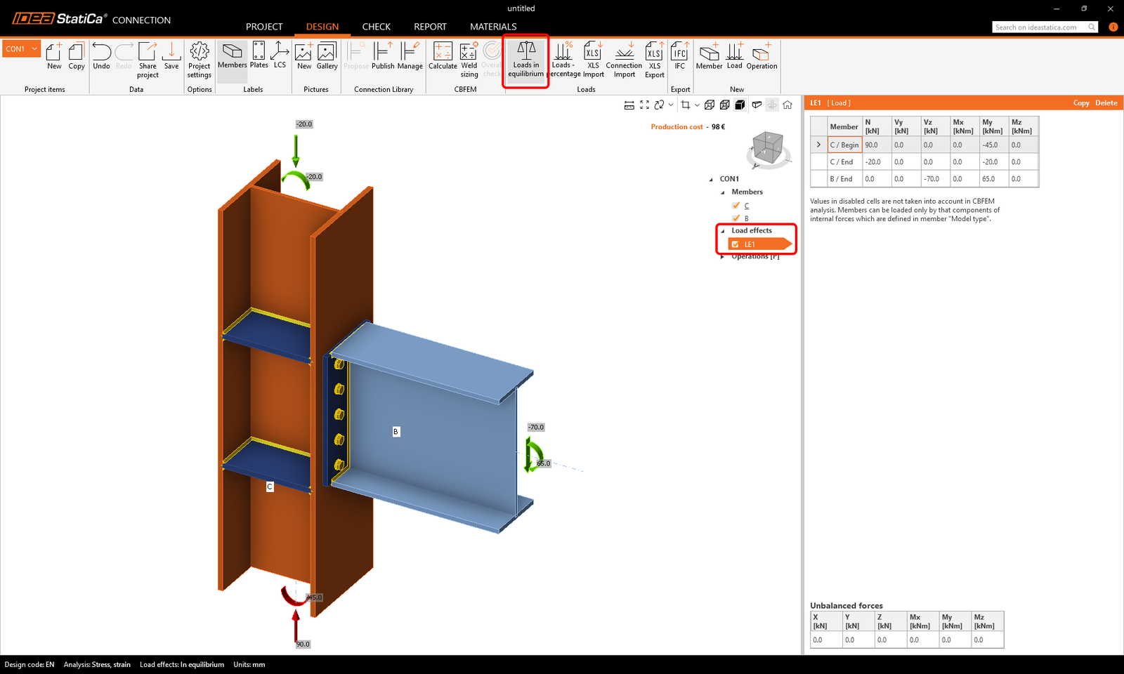
In the Load effects, you define the internal forces in the connection node for each member. It is important to keep the defined loads in equilibrium. Keep the internal forces inserted by the template.
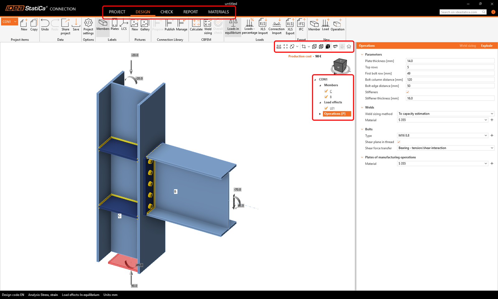
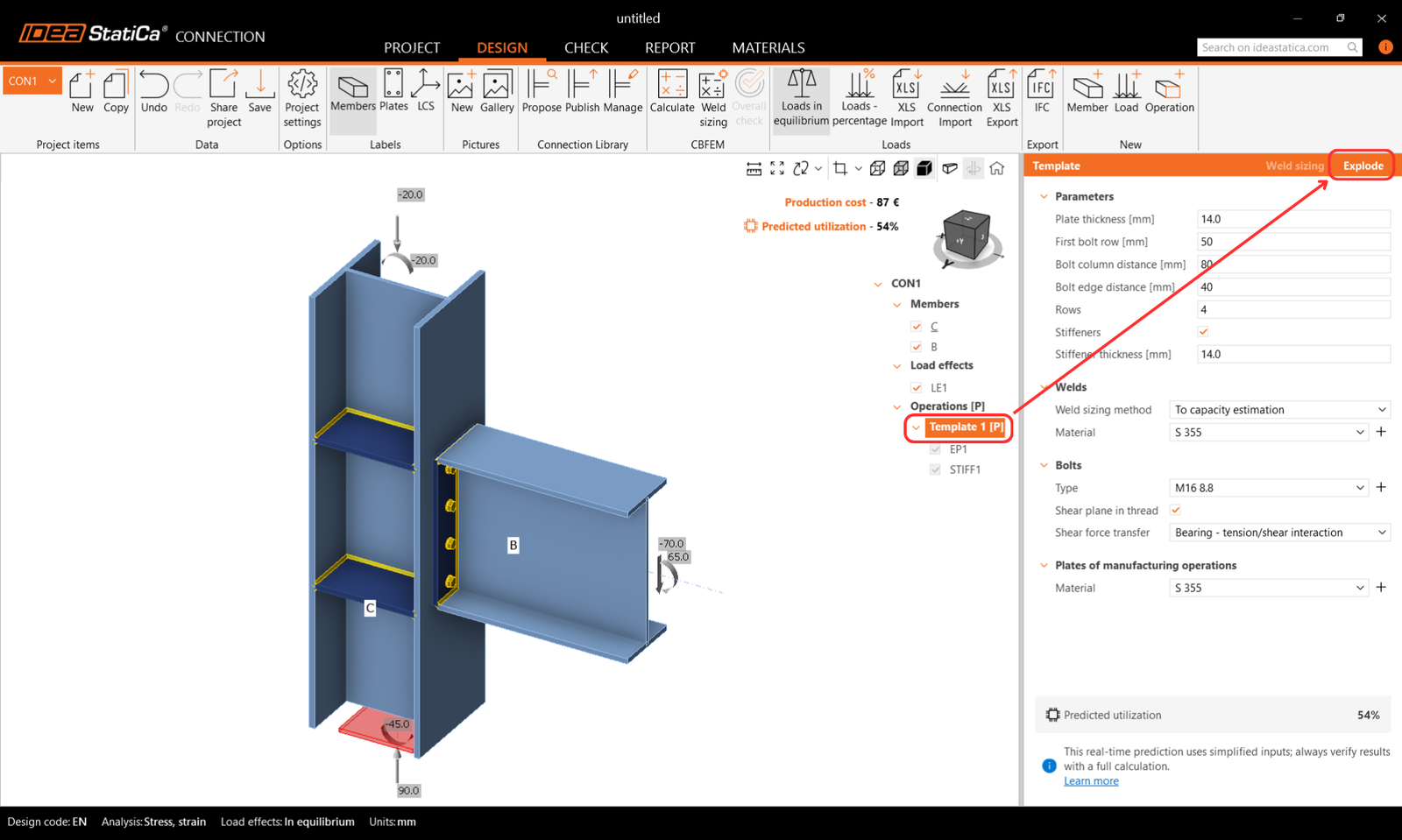
In the Operations section, you define the connection design. With the selected parametric template, you can edit properties of your design in the Operations tab directly.
Change the number of bolts to 4 in the Rows parameter and the stiffener thickness to 14 mm in the Stiffeners parameter.
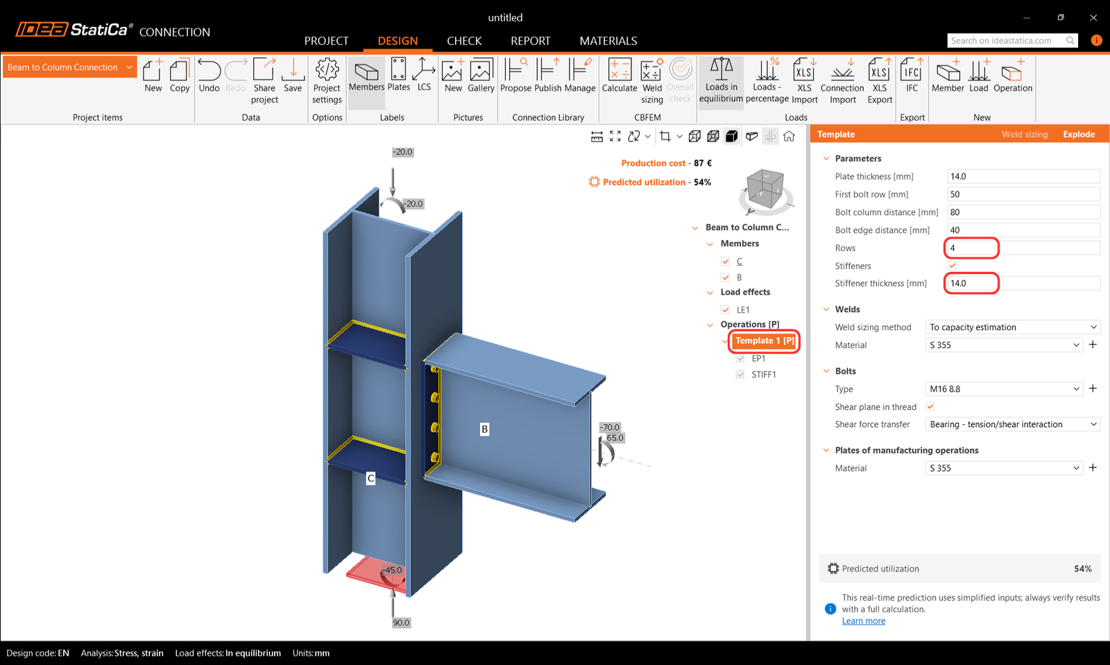
Note: The manufacturing operations within the parametric template are hidden and disabled for editing. If you want to work with the properties of manufacturing operations instead, you can Explode the parametric template.
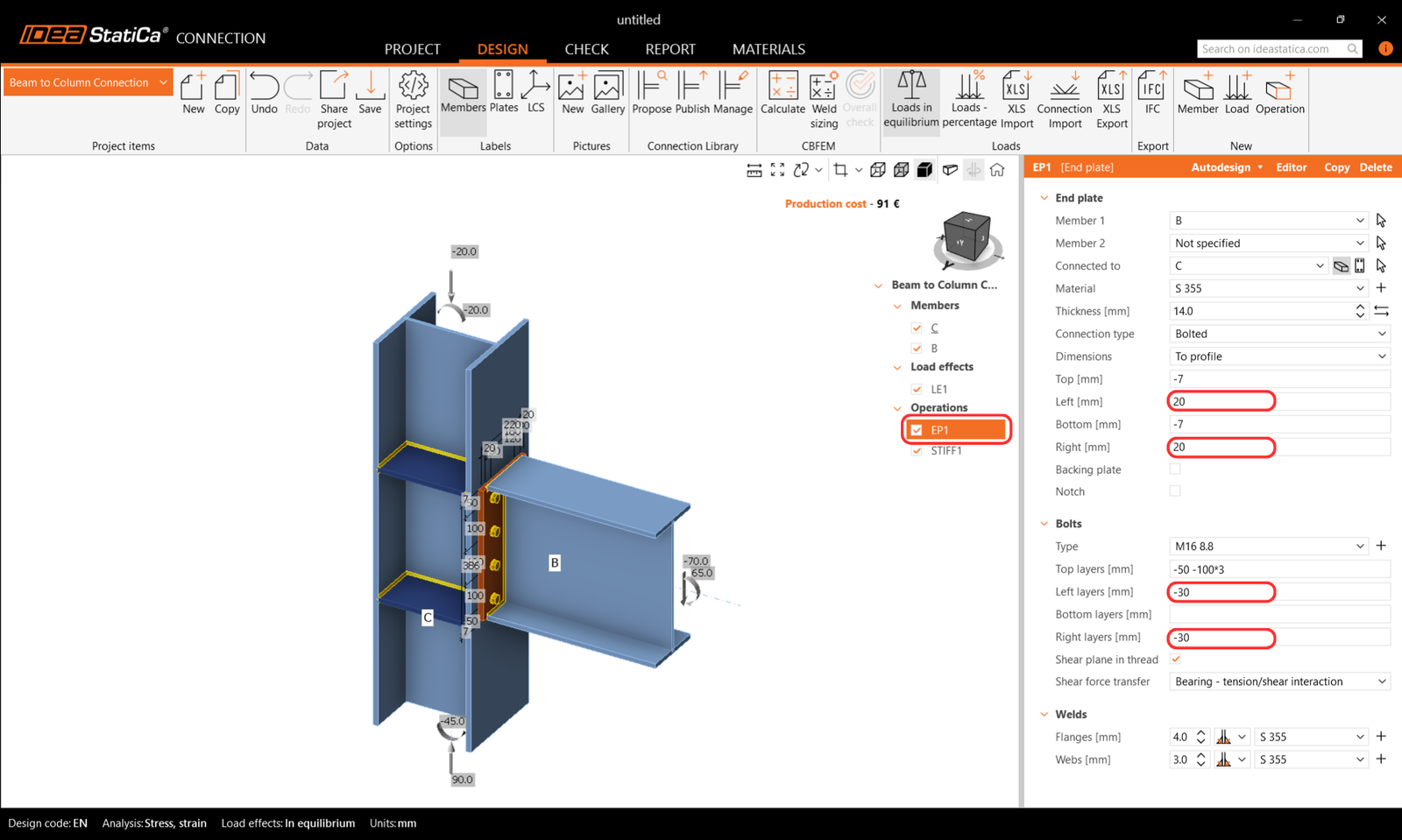
Then you can edit and delete each manufacturing operation separately to achieve a different connection assembly. Change the parameters Left and Right in End plate to 20mm, and Left layers and Right layers in Bolts to -30mm. Also, you can always add a new manufacturing operation.
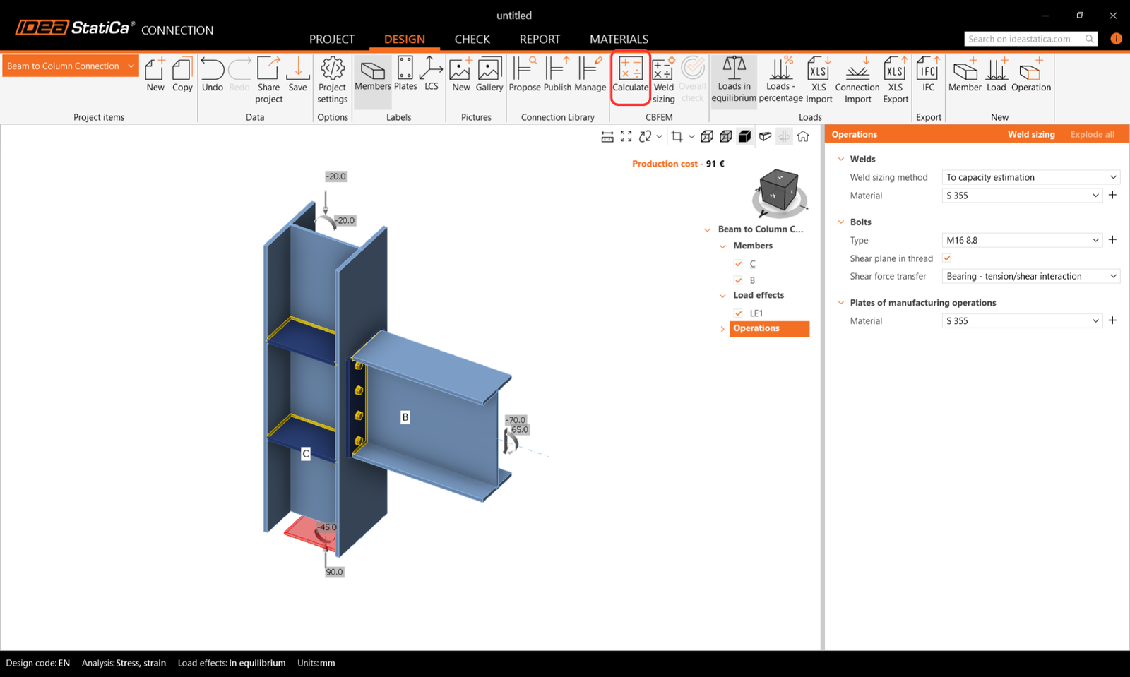
2 Calculation and check
To start the calculation and code check, press Calculate on the top ribbon.
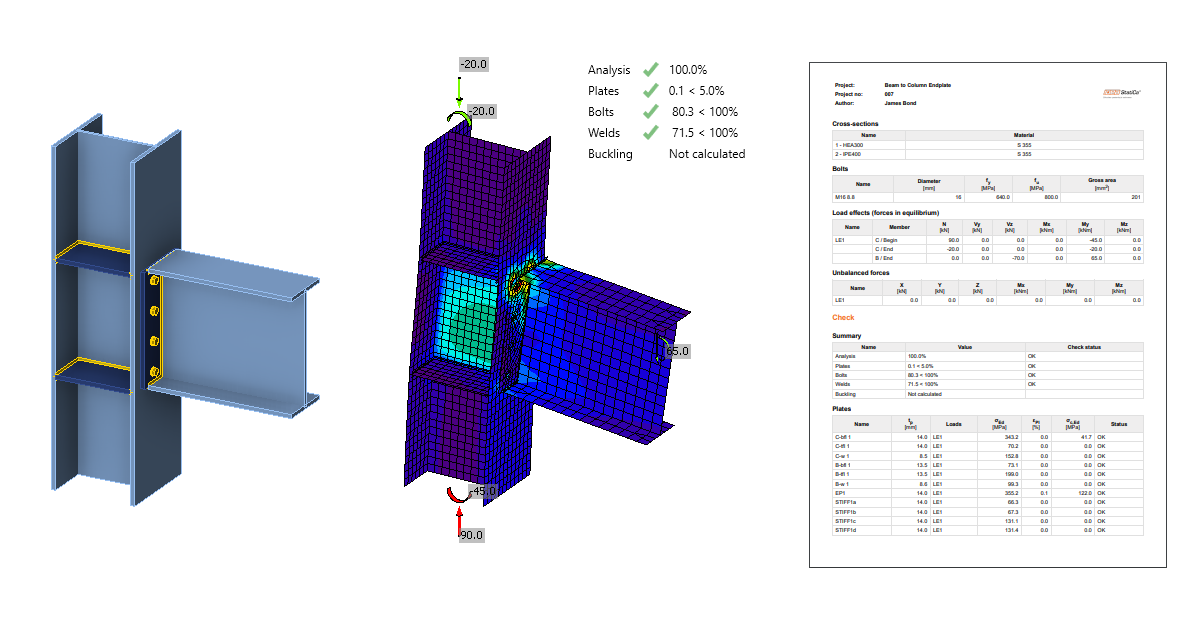
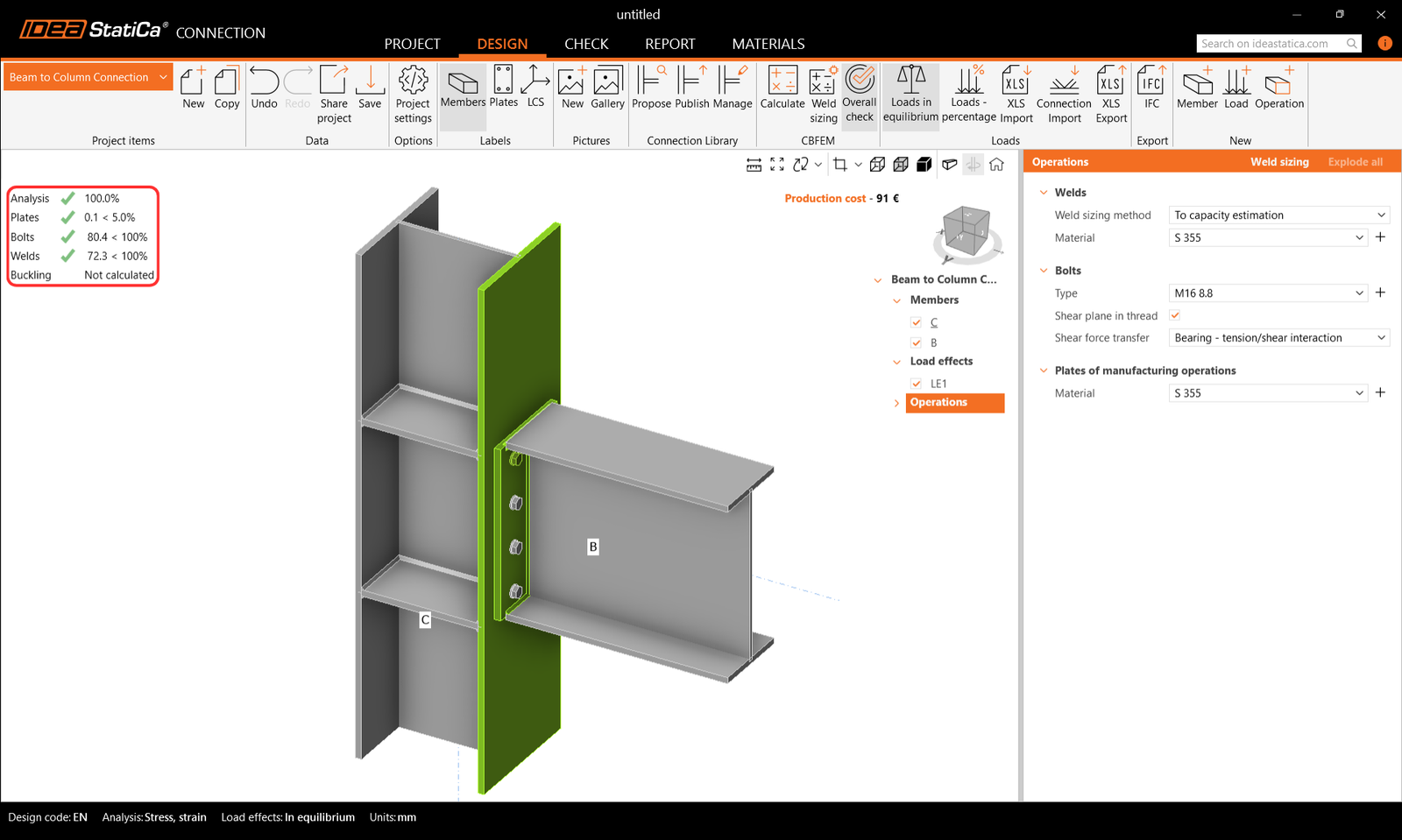
You immediately see the overall results showing the utilization level of each component type (grey for utilization under 60%, green for 60–95%, orange for 95–100%, and red for utilization over 100%, i.e., for failing components).
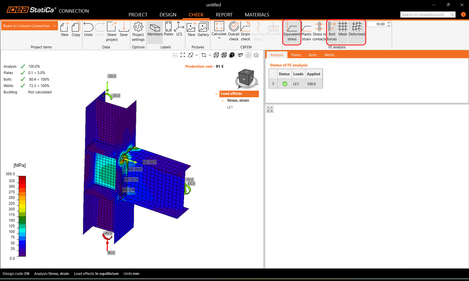
To see the detailed results, go to the Check tab. You can review the stress-strain analysis results and observe the connection behavior using the ribbon commands – turn on the Equivalent stress and then Mesh display, Deformed shape, and Bolt forces (tensile forces in bolts).
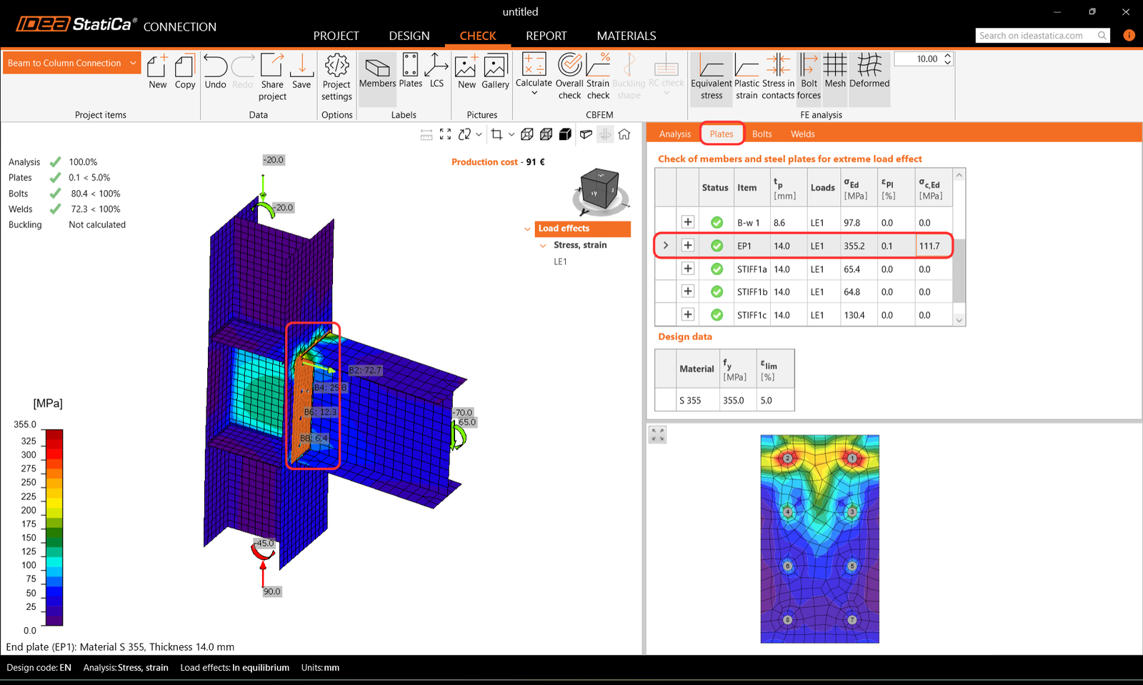
When you select the endplate in the 3D scene, the Plates tab appears. The plate is highlighted in the tab and displayed in a 2D screen under the table.
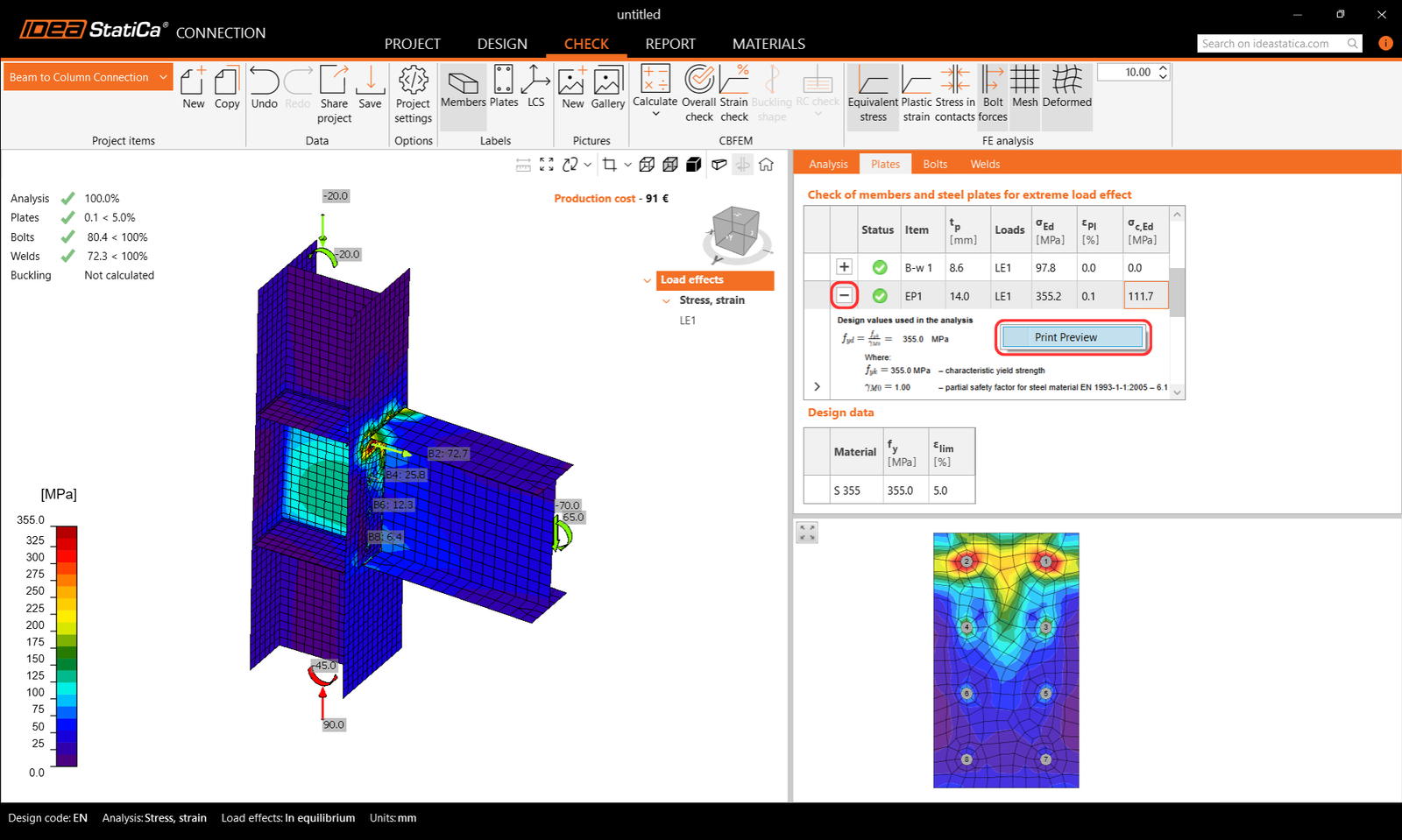
Next to reading the main results in the highlighted row in the tab, you can click on the "+ button" to reveal the code check equations. Enlarge the equations with Print Preview using the right-click.
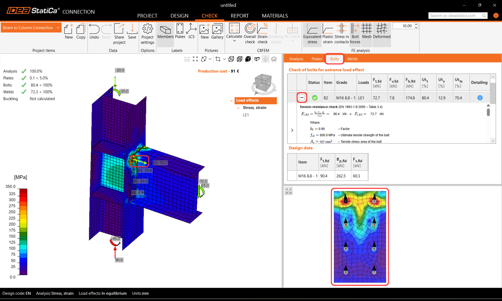
If you click on a bolt or a bolt force in the 3D window, the Bolts tab is shown likewise. You can see the directions of shear forces in bolts in the 2D screen under the table, and read through the equations via the "+ button".
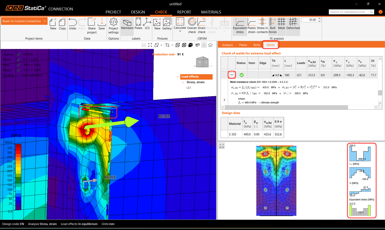
The same logic works for welds in the Welds tab. Welds have their own mesh elements, and once selected, the stress diagrams are displayed in the 2D screen below the tab. Again, code check equations can be browsed using the "+ button".
3 Report
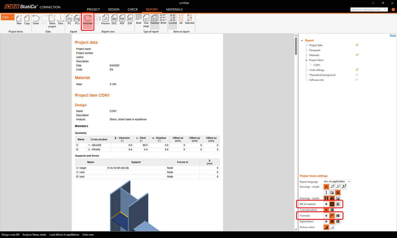
When the design and code check is done, you can print your report in the Report tab. The report is fully customizable. For example, you can add the code check equations for each component type by selecting the Formulas icon, as well as the Bill of material. Once set, click the Generate button.
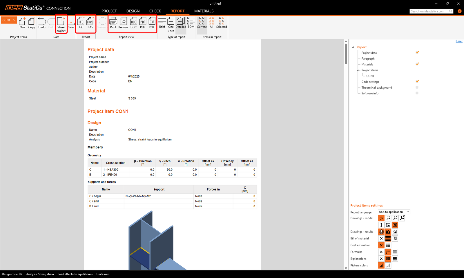
The report is generated, and you can save it in PDF or DOC (Microsoft Word) format, or Print it right away. You can also export a 3D IFC model, 2D drawings of plates by pressing the DXF button, and share the connection model in the online Viewer (there you can also export a 3D DWG file).
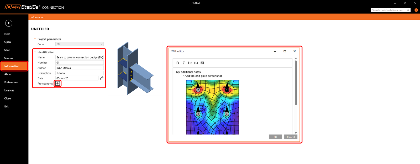
To edit the report header, go to the Project tab.
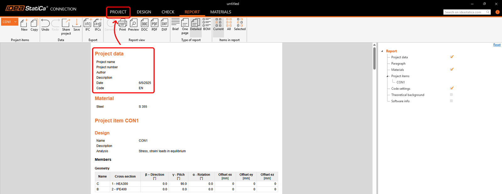
Here, you can add the Project name, number, author, description, date, and written notes with pictures for each project item (CON1) or all project items at once.
Then, Generate the report again, don't forget to Save your project, and you are done!
You can continue learning IDEA StatiCa with many more tutorials in our Support center.
Learn how to use IDEA StatiCa effectively with our self-paced e-learning courses
Start learning