
Catalog al stărilor limită AISC și al cerințelor de proiectare
Introducere
Proiectarea îmbinărilor din oțel structural necesită evaluarea multor stări limită, luarea în considerare a multor efecte de comportament și respectarea multor cerințe. Specificația AISC, Manualul AISC și alte referințe descriu metodele de proiectare utilizate în practica din SUA. În prezent, cele mai utilizate metode se bazează predominant pe calcule care pot fi efectuate manual. Cu toate acestea, progresele în hardware și software permit un alt tip de proiectare, bazat pe analiza structurală neliniară.
Utilizarea analizei neliniare în proiectare poate fi avantajoasă pentru îmbinări complexe sau unice, unde ipotezele calculelor tradiționale nu sunt demonstrate. Cu toate acestea, aceleași stări limită, considerații de proiectare și cerințe de proiectare se aplică. O proiectare bună a îmbinărilor provine de la ingineri care cunosc aceste criterii de proiectare și modul în care instrumentele lor le captează.
Acest document este destinat să fie o listă detaliată, dar nu exhaustivă, a stărilor limită, considerațiilor de proiectare și cerințelor de proiectare relevante pentru proiectarea structurilor din oțel și o descriere a modului în care acestea sunt luate în considerare în calculele tradiționale și în IDEA StatiCa folosind metoda elementelor finite bazată pe componente.
Acest document este actualizat în mod constant, deoarece exercițiile de verificare și investigare sunt încă în desfășurare.
Conținutul acestui articol face referire la Specificația AISC din 2022 și la Manualul AISC, ediția a 16-a.
Stări limită
Ruperea sudurii
Specificația AISC include prevederi pentru suduri cap la cap, suduri de colț și suduri în gaură sau în fantă. Dintre acestea, sudurile cap la cap cu penetrare completă a îmbinării (CJP) și sudurile de colț sunt singurele tipuri care pot fi definite în prezent în IDEA StatiCa.
Sudurile cap la cap CJP și sudurile butt weld în IDEA StatiCa sunt modelate prin conectarea directă a componentelor folosind constrângeri multi-punct. Constrângerile multi-punct nu introduc flexibilitate. De asemenea, rezistența acestor suduri nu este verificată, deoarece rezistența sudurilor cap la cap CJP este controlată de metalul de bază.
Sudurile de colț sunt, de asemenea, modelate folosind constrângeri multi-punct și un element de tip placă echivalentă a sudurii care aproximează comportamentul elastoplastic al sudurii. Forțele din aceste elemente de tip placă sunt extrase și utilizate ca rezistențe solicitate pentru comparație cu rezistențele disponibile calculate conform Specificației AISC.
Rezistența disponibilă a sudurilor este definită în Secțiunea J2.4 a Specificației AISC. Pentru sudurile de colț, rezistența nominală este produsul dintre tensiunea nominală a metalului de sudură, Fnw, aria efectivă a sudurii, Awe, și un factor de creștere a rezistenței în funcție de direcție, kds. Tabelul J2.5 din Specificația AISC stabilește Fnw = 0,6FEXX și face referire la Secțiunea J2.2a din Specificația AISC pentru definiția Awe. Pentru fiecare segment de sudură, Awe este luată ca grosimea gâtului înmulțită cu lungimea segmentului de sudură. Reducerile lungimii efective pentru suduri lungi din Secțiunea J2.2b a Specificației AISC nu sunt aplicate; cu toate acestea, efectele sudurilor lungi sunt captate explicit, după cum este descris în intrarea privind Compatibilitatea Deformațiilor în Îmbinările Lungi.
Factorul de creștere a rezistenței în funcție de direcție este definit în Secțiunea J2.4 a Specificației AISC. Când compatibilitatea deformațiilor diferitelor elemente de sudură este luată în considerare (cum este cazul în IDEA StatiCa, deoarece rigiditatea sudurilor și a elementelor de conectare sunt modelate explicit), kds este o funcție a unghiului dintre direcția forței solicitate și axa longitudinală a sudurii. IDEA StatiCa determină direcția forței din forțele interioare ale elementului de tip placă echivalentă a sudurii și calculează kds și rezistența nominală pentru fiecare segment de sudură.
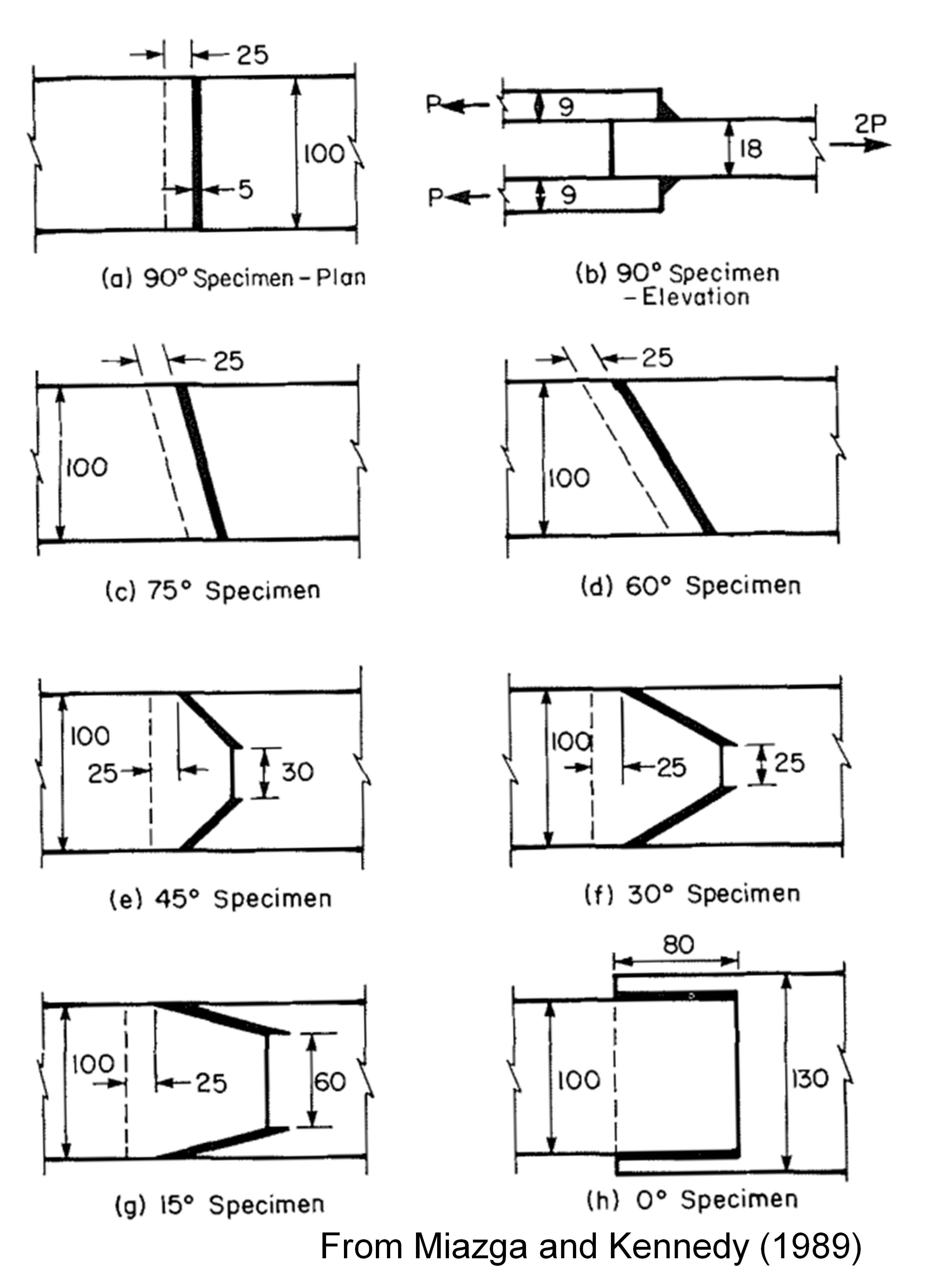
Pentru a ilustra efectul creșterii rezistenței în funcție de direcție, se consideră specimenele sudate testate experimental de Miazga și Kennedy (1989). Specimenele au avut unghiuri de încărcare de 0, 15, 30, 45, 60, 75 și 90 de grade, după cum se arată în figura de mai jos, unde unitățile sunt milimetri. Plăcile au fost fabricate din oțel CAN3-G40.21-M8 grad 300W. Plăcile exterioare au avut o limită de curgere măsurată de 52,8 ksi. Plăcile interioare au avut o limită de curgere măsurată de 50,2 ksi. Au fost utilizați electrozi E48014 cu o rezistență nominală de FEXX = 70 ksi.
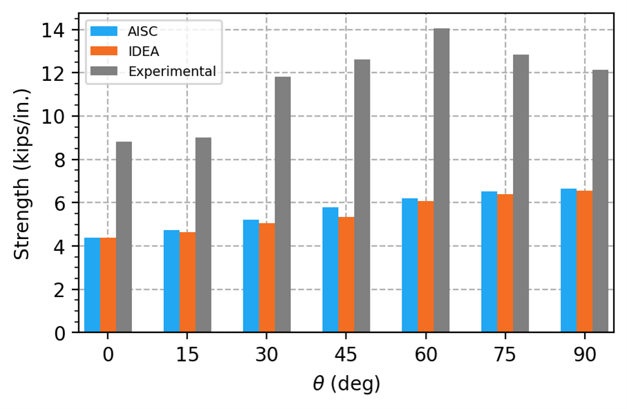
Sarcinile aplicate maxime admise au fost determinate pentru fiecare specimen în IDEA StatiCa folosind modele cu proprietăți măsurate ale materialului plăcilor, proprietăți nominale ale metalului de adaos și incluzând factorii de rezistență. Sarcinile aplicate maxime admise au fost normalizate prin lungimea totală a sudurii din îmbinare și sunt prezentate în figura de mai jos. De asemenea, sunt prezentate rezistența de calcul conform Specificației AISC (incluzând factorul de creștere a rezistenței în funcție de direcție și factorul de rezistență) și rezistența experimentală.
Unghiul de încărcare măsurat față de axa longitudinală a sudurii pentru fiecare specimen, așa cum este furnizat de IDEA StatiCa în rezultatele sudurii, este listat în tabelul de mai jos.
| Geometric \(\theta\) (deg) | IDEA \(\theta\) (deg) |
| 0 | 14,7 |
| 15 | 21,1 |
| 30 | 34,0 |
| 45 | 49,1 |
| 60 | 58,8 |
| 75 | 72,6 |
| 90 | 89,9 |
Rezistențele din IDEA StatiCa și din Specificația AISC sunt ambele mult mai mici decât rezistențele experimentale. Există mai multe motive pentru care rezistențele experimentale sunt mai mari: acestea nu includ factorii de rezistență, rezistența reală a metalului de adaos este probabil mai mare decât rezistența nominală, iar aria reală de cedare a sudurii este probabil mai mare decât cea asumată în calculele de proiectare.
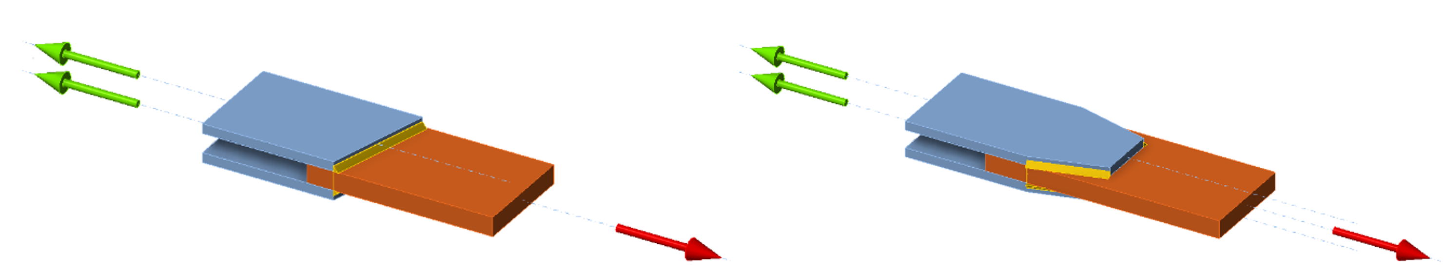
Rezistențele din IDEA StatiCa sunt ușor mai mici decât cele conform Specificației AISC, dar ambele prezintă o creștere odată cu unghiul de încărcare. Mai mult, unghiul geometric al specimenului diferă de unghiul de încărcare măsurat față de axa longitudinală a sudurii, așa cum este furnizat de IDEA StatiCa. Aceste diferențe apar deoarece sudurile sunt împărțite în segmente scurte atunci când sunt modelate în IDEA StatiCa. Spre deosebire de calculele tradiționale, unde solicitările de-a lungul lungimii sudurii sunt presupuse uniforme, segmentele de sudură experimentează solicitări diferite în funcție de rigiditatea sudurii și a elementelor de conectare. Unghiul furnizat de IDEA StatiCa este pentru segmentul de sudură care are cel mai mare grad de utilizare. Adesea acesta este un segment la capătul unei suduri. Pentru aceste specimene, efectul agregat al solicitărilor neuniforme este o ușoară reducere a rezistenței.
Un caz special se aplică pentru sudurile de colț la capetele profilelor HSS rectangulare încărcate la întindere, unde kds = 1,0. În IDEA StatiCa, factorul de creștere a rezistenței în funcție de direcție nu este utilizat pentru sudurile de colț la capetele profilelor HSS rectangulare, indiferent de încărcare.
Secțiunea J2.4 a Specificației AISC definește, de asemenea, rezistența metalului de bază. Pentru sudurile de colț, Tabelul J2.5 al Specificației AISC face referire la Secțiunea J4 a Specificației AISC pentru verificările metalului de bază. Verificările rezistenței metalului de bază al sudurii sunt descrise mai detaliat în intrarea privind Rezistența Metalului de Bază al Sudurii.
Rezistența Metalului de Bază al Sudurii
În îmbinările sudate, rezistența elementelor de conectare adiacente sudurii se numește rezistența metalului de bază. În multe cazuri, stările limită potențiale pot fi identificate, iar rezistența disponibilă a metalului de bază poate fi calculată folosind prevederile Secțiunii J4 a Specificației AISC. Evaluarea acestor stări limită în IDEA StatiCa este descrisă în intrările privind stările limită individuale, inclusiv Curgerea la Întindere, Ruperea la Întindere, Curgerea și Ruperea la Forfecare și Ruperea prin Forfecare în Bloc.
Cu toate acestea, în unele îmbinări, stările limită potențiale adiacente sudurii sunt greu de identificat, iar rezistența disponibilă a metalului de bază nu poate fi calculată direct manual. Pentru aceste cazuri, Manualul AISC furnizează Ecuațiile 9-6 și 9-7 pentru grosimea minimă a metalului de bază care corespunde sudurii cu anumite ipoteze. Această ecuație nu este evaluată în IDEA StatiCa, deoarece stările limită potențiale ale metalului de bază nu trebuie identificate a priori, iar rezistența este evaluată cu limita de deformație plastică de 5%. Cu toate acestea, inginerii pot utiliza în continuare această limită pentru dimensionarea sudurilor și a elementelor de conectare.
IDEA StatiCa oferă o opțiune de verificare a capacității metalului de bază la fața de fuziune. Această verificare poate fi activată în fereastra „Code setup". Această verificare nu este efectuată în mod obișnuit în practica din SUA și, în general, nu este necesară atunci când metalul de adaos este potrivit corespunzător cu metalul de bază. Comentariul la Secțiunea J2.4 a Specificației AISC precizează că testele au demonstrat că tensiunea pe zona de fuziune nu este critică în determinarea rezistenței la forfecare a sudurilor de colț.
Ruperea Șuruburilor la Forfecare și Întindere
Rezistența disponibilă a șuruburilor supuse la întindere sau forfecare este definită în Secțiunea J3.7 a Specificației AISC. Rezistența disponibilă a șuruburilor supuse la întindere și forfecare combinate este definită în Secțiunea J3.8 a Specificației AISC. IDEA StatiCa utilizează aceste prevederi direct pentru a calcula rezistențele disponibile, comparate cu rezistențele solicitate determinate din analiza neliniară. Conform specificației, rezistența la întindere solicitată determinată din analiza neliniară include întinderea rezultată din efectul de pârghie.
O notă de subsol din Tabelul J3.2 al Specificației AISC impune ca tensiunea nominală de forfecare, Fnv, a șuruburilor A307 să fie redusă atunci când prinderea unui șurub este mai mare de cinci ori diametrul său. Această reducere nu este implementată în IDEA StatiCa. Prin urmare, tensiunea nominală de forfecare a șuruburilor lungi A307 trebuie ajustată manual în fila materialelor.
Presiunea de Contact și Smulgerea la Găurile de Șurub
Rezistența șuruburilor la forfecare poate fi limitată de presiunea de contact sau de smulgere la găurile de șurub. Uneori este practică obișnuită să se evalueze presiunea de contact și smulgerea separat de ruperea la forfecare a șurubului. Cu toate acestea, grupurile de șuruburi pot ceda cu unele șuruburi rupând și altele smulgând. O notă de utilizator din Secțiunea J3.7 a Specificației AISC precizează: „Rezistența efectivă a unui dispozitiv de fixare individual poate fi luată ca valoarea minimă dintre rezistența la forfecare a dispozitivului de fixare conform Secțiunii J3.7 sau rezistența la presiune de contact sau smulgere la gaura de șurub conform Secțiunii J3.11. Rezistența grupului de șuruburi este luată ca suma rezistențelor efective ale dispozitivelor de fixare individuale."
IDEA StatiCa evaluează rezistența fiecărui șurub individual, cu rezistențele solicitate determinate din analiza neliniară și rezistențele disponibile calculate folosind prevederile Specificației AISC. Această evaluare respectă nota de utilizator din Secțiunea J3.7 a Specificației AISC. Cu toate acestea, IDEA StatiCa nu sumează pur și simplu rezistențele efective ale dispozitivelor de fixare individuale. Abordarea adoptată de IDEA StatiCa poate duce la o subestimare conservatoare a rezistenței.
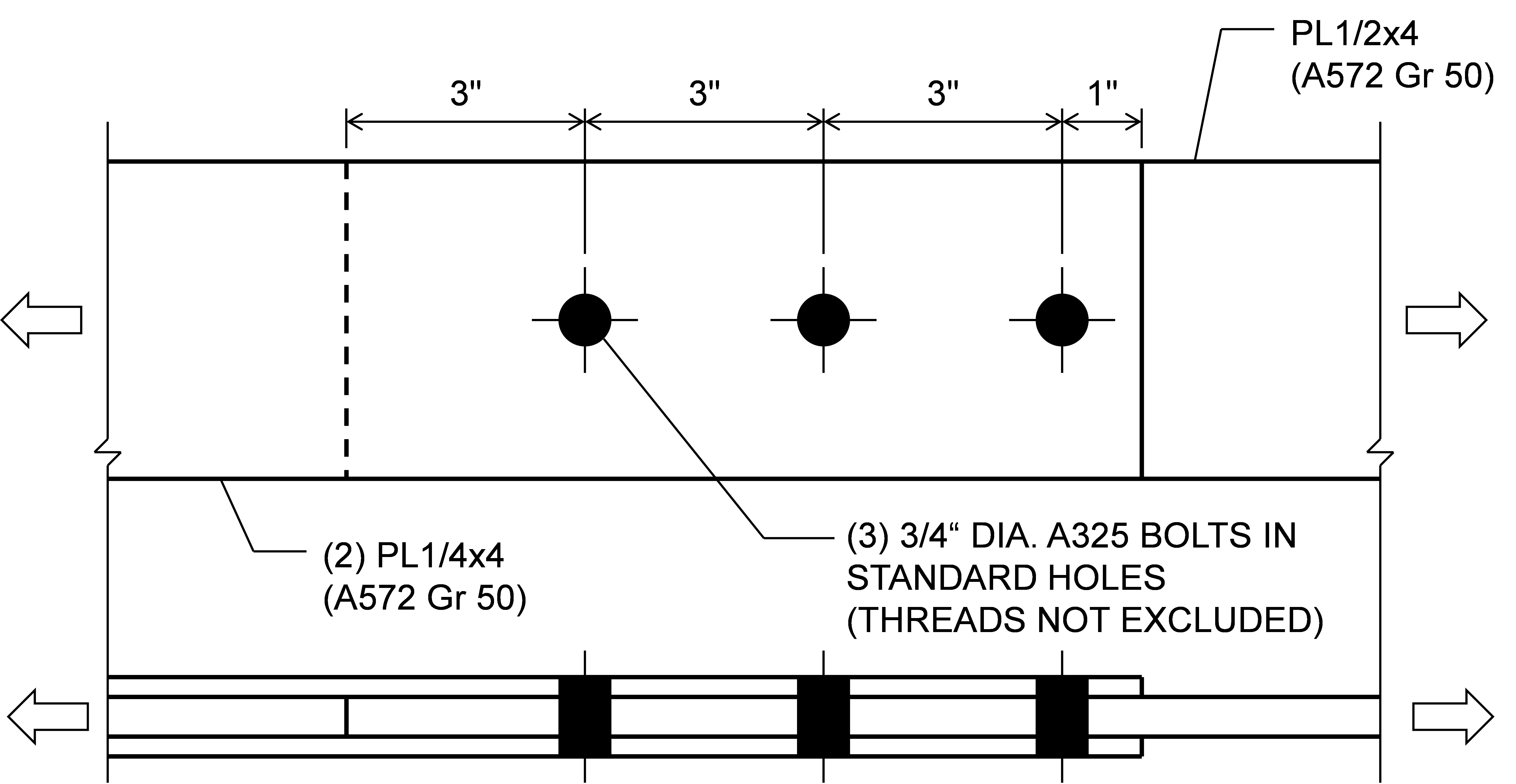
Se consideră îmbinarea cu trei șuruburi prezentată mai jos. Îmbinarea este scurtă și rigiditatea celor trei șuruburi este egală, deoarece răspunsul forță-deformație pentru șuruburi în IDEA StatiCa nu depinde de distanța față de margine, prin urmare sarcina aplicată este distribuită aproximativ egal între șuruburi. Rezistența șurubului cu distanța față de margine de 1 in. este controlată de smulgere. IDEA StatiCa indică cedarea atunci când primul șurub atinge un grad de utilizare de 100%. Deoarece șurubul cu distanța față de margine de 1 in. are cea mai mică rezistență disponibilă (ϕrn = ϕ1,2dtFu = 17,4 kips), acesta atinge primul 100% grad de utilizare. Celelalte șuruburi sunt mai rezistente (ϕrn = 35,8 kips, Tabelul 7-1 din Manualul AISC), dar nu ating 100% grad de utilizare, rezultând o rezistență a îmbinării de 52,5 kips. Prin calcule tradiționale, se presupune că fiecare șurub atinge rezistența sa efectivă, rezultând o rezistență a îmbinării de 89,0 kips, cu 70% mai mare decât rezistența din IDEA StatiCa.
Îmbinare cu trei șuruburi
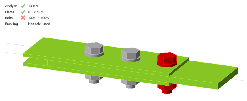
Îmbinare cu trei șuruburi cu o sarcină aplicată de 57,5 kips
Două seturi de ecuații sunt furnizate în Secțiunea J3.11a a Specificației AISC, unul când deformația la gaura de șurub la sarcina de serviciu este o considerație de proiectare și unul când deformația la gaura de șurub la sarcina de serviciu nu este o considerație de proiectare. Alegerea dacă deformația la gaura de șurub la sarcina de serviciu este o considerație de proiectare poate fi făcută în fereastra „Code setup".
Ecuații diferite sunt, de asemenea, furnizate în Secțiunea J3.11a a Specificației AISC pentru găuri cu fante lungi când fanta este perpendiculară pe direcția forței. Găurile cu fante pot fi definite în IDEA StatiCa folosind editorul de plăci. Ecuațiile de presiune de contact și smulgere din Specificația AISC pentru găuri cu fante lungi sunt utilizate pentru toate găurile cu fante în IDEA StatiCa, indiferent de lungimea fantei.
Secțiunea J3.11b a Specificației AISC impune utilizarea prevederilor de presiune de contact din Secțiunea J7 pentru șuruburi sau tije care trec complet printr-un element tip cutie nerigidizat sau profil tubular structural (HSS). Această prevedere nu este implementată în IDEA StatiCa, iar presiunea de contact este evaluată în astfel de îmbinări ca și cum ar fi îmbinări obișnuite cu șuruburi cu toate straturile în contact ferm. Un avertisment este furnizat în raport dacă lungimea de prindere a șurubului este mai mare decât suma grosimilor plăcilor conectate.
La evaluarea smulgerii, IDEA StatiCa determină distanța liberă, în direcția forței, între marginea găurii și marginea găurii adiacente sau marginea materialului, lc, folosind direcția forței pentru fiecare șurub din analiza neliniară. Această funcție este deosebit de utilă pentru grupurile de șuruburi încărcate excentric, unde direcția forței variază de la un șurub la altul. Starea limită de smulgere a fost investigată pentru îmbinările cu placă de consolă în acest articol și pentru îmbinările cu placă de inimă la forfecare în acest articol.
Presiunea de Contact (Curgere Locală la Compresiune)
Secțiunea J7 a Specificației AISC definește rezistența disponibilă pentru starea limită de presiune de contact (curgere locală la compresiune). Aceste prevederi se aplică unor cazuri specifice de contact între componente din oțel, dar nu sunt implementate în IDEA StatiCa.
Pentru suprafețele finisate și capetele elementelor de rigidizare de reazem ajustate, deși presiunea de contact nu este verificată față de limita prescrisă în Specificația AISC, tensiunile în contacte pot fi reprezentate grafic, iar curgerea componentelor din oțel oferă adesea o limită mai restrictivă, deoarece presiunea admisă de contact depășește limita de curgere.
IDEA StatiCa evaluează rezistența la presiune de contact a șuruburilor sau tijelor care trec complet printr-un element tip cutie sau HSS nerigidizat ca și cum ar fi îmbinări obișnuite cu șuruburi cu toate straturile în contact ferm și fără a utiliza prevederile Secțiunii J7 a Specificației AISC. Un avertisment este furnizat în raport dacă lungimea de prindere a șurubului este mai mare decât suma grosimilor plăcilor conectate. A se vedea și Presiunea de Contact și Smulgerea la Găurile de Șurub.
Rolele de expansiune și balansierele nu pot fi modelate în IDEA StatiCa. Bolțurile au fost introduse în IDEA StatiCa în versiunea 24.0 și sunt disponibile în prezent doar pentru proiectarea conform Eurocode.
Alunecare
Îmbinările trebuie proiectate ca îmbinări rezistente la alunecare atunci când sunt supuse la sarcini de oboseală cu inversarea direcției de încărcare, când utilizează găuri supradimensionate, când alunecarea la suprafețele de contact ar fi dăunătoare pentru performanța structurii și din alte motive. Rezistența disponibilă pentru starea limită de alunecare este definită în Secțiunea J3.9 a Specificației AISC, cu prevederi suplimentare în Secțiunea J3.10 pentru întindere și forfecare combinate în îmbinările rezistente la alunecare. IDEA StatiCa utilizează aceste prevederi direct pentru a calcula rezistențele disponibile, care sunt comparate cu rezistențele solicitate determinate din analiza neliniară.
Coeficientul de alunecare, μ, este definit în configurarea codului. Factorul pentru plăci de umplutură, hf, este determinat automat.
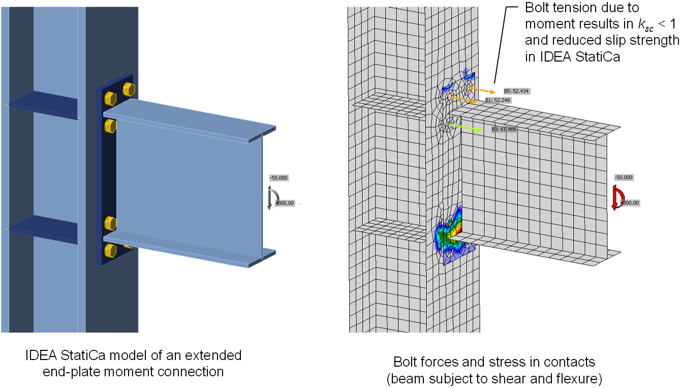
Diferențele dintre IDEA StatiCa și calculele manuale pot apărea din cauza factorului de reducere pentru întindere, ksc, definit în Secțiunea J3.10 a Specificației AISC. IDEA StatiCa utilizează întinderea din șurub din analiza neliniară pentru a calcula ksc, chiar dacă întinderea din șurub nu a fost cauzată de o forță de întindere aplicată care reduce forța netă de strângere. De exemplu, într-o îmbinare cu placă de capăt extinsă cu moment, cu o îmbinare rezistentă la alunecare între placa de capăt și talpa stâlpului (cum se arată mai jos), momentul din grindă cauzează întindere în șuruburi în IDEA StatiCa. Fizic, orice pierdere a forței de strângere în apropierea șuruburilor de pe partea întinsă a grinzii datorată momentului va fi compensată de o creștere a forței de strângere în apropierea șuruburilor de pe partea comprimată a grinzii. În calculele manuale, factorul ksc nu ar fi utilizat pentru această îmbinare (cu excepția cazului în care grinda are o forță netă de întindere). Dar deoarece IDEA StatiCa evaluează șuruburile individual, ksc este aplicat conservativ șuruburilor de pe partea întinsă a grinzii, reducând rezistența globală la alunecare a îmbinării. Întinderea incidentală într-o îmbinare predominant solicitată la forfecare și întinderea din efectul de pârghie sunt, de asemenea, incluse conservativ la calculul ksc în IDEA StatiCa.
Secțiunea J3.9 a Specificației AISC impune ca îmbinările rezistente la alunecare să fie proiectate și pentru stările limită ale îmbinărilor de tip presiune de contact, pe lângă alunecare. IDEA StatiCa nu verifică ruperea șuruburilor, presiunea de contact sau smulgerea pentru șuruburile destinate transferului de forță prin frecare. În plus, îmbinările rezistente la alunecare sunt modelate diferit față de îmbinările de tip presiune de contact în IDEA StatiCa. În îmbinările rezistente la alunecare, forțele sunt transferate de la o placă la alta pe o suprafață mai mare, mai reprezentativă pentru transferul de forță prin frecare. Distribuția mai largă a forțelor de transfer poate duce la creșterea rezistenței elementelor de conectare pentru stări limită precum ruperea prin forfecare în bloc. Pentru majoritatea îmbinărilor, rezistența la alunecare este mai mică decât rezistența pentru stările limită ale îmbinărilor de tip presiune de contact. Cu toate acestea, inginerii trebuie să fie conștienți de aceste limitări și să le abordeze în proiectare. Se recomandă ca îmbinările rezistente la alunecare să fie analizate de două ori în IDEA StatiCa: o dată ca îmbinare rezistentă la alunecare (adică, cu tipul de transfer al forței de forfecare setat pe „Friction") și din nou ca îmbinare de tip presiune de contact (adică, cu tipul de transfer al forței de forfecare setat pe „Bearing – tension/shear interaction") pentru a se asigura că toate stările limită sunt evaluate corespunzător.
Curgerea la Întindere
Curgerea la întindere este una dintre cele mai fundamentale stări limită în proiectarea structurilor din oțel. Rezistența nominală pentru curgerea la întindere este definită în Secțiunea D2 a Specificației AISC (2022) pentru elementele solicitate la întindere și în Secțiunea J4.1 pentru elementele de conectare, ca tensiunea minimă specificată de curgere, Fy, înmulțită cu aria brută, Ag. În ciuda simplității acestei ecuații, ea nu este utilizată pentru evaluarea rezistenței în IDEA StatiCa. Elementele și componentele de conectare sunt modelate în IDEA StatiCa cu elemente de tip placă cărora li se atribuie o relație neliniară efort-deformație constând dintr-o regiune liniară elastică și o regiune liniară plastică. Elementele de tip placă pot experimenta tensiuni pe mai multe axe, iar relațiile efort-deformație țin cont de acest lucru. Dacă sunt supuse la tensiune uniaxială, rigiditatea în domeniul elastic este modulul de elasticitate, E, rigiditatea în domeniul plastic este o miime din modulul de elasticitate, E/1000, iar tranziția dintre elastic și plastic are loc la o tensiune de Fy înmulțită cu un factor de rezistență de 0,9 pentru LRFD sau împărțită la un factor de siguranță de 1,67 pentru ASD.
În loc să limiteze rezistența solicitată la cel mult rezistența disponibilă (de ex., Ru ≤ ϕRn), IDEA StatiCa limitează deformația plastică la 5%. Deși aceasta este o evaluare fundamental diferită, rezistențele rezultante pentru curgerea la întindere a secțiunii brute a unui element sau componente din cele două abordări nu vor diferi niciodată cu o valoare mare. Diferențe minore pot apărea din două motive: 1) mica creștere a tensiunii după curgere în IDEA StatiCa și 2) mici diferențe în aria secțiunii transversale.
O rigiditate post-curgere mică (o miime din rigiditatea elastică) este utilizată în IDEA StatiCa pentru a evita dificultățile de calcul care ar apărea cu o rigiditate post-curgere nulă. La limita de deformație plastică de 5%, aceasta rezultă în aproximativ 0,05×E/1000 = 0,05×(29.000 ksi)/1000 = 1,45 ksi tensiune peste tensiunea de curgere. Pentru oțelul ASTM A992 cu Fy de 50 ksi și utilizând LRFD, curgerea la întindere începe în IDEA StatiCa la 0,9×50 ksi = 45 ksi. Cei 1,45 ksi suplimentari de tensiune acumulați post-curgere pot duce la o creștere de aproximativ 3% a rezistenței.
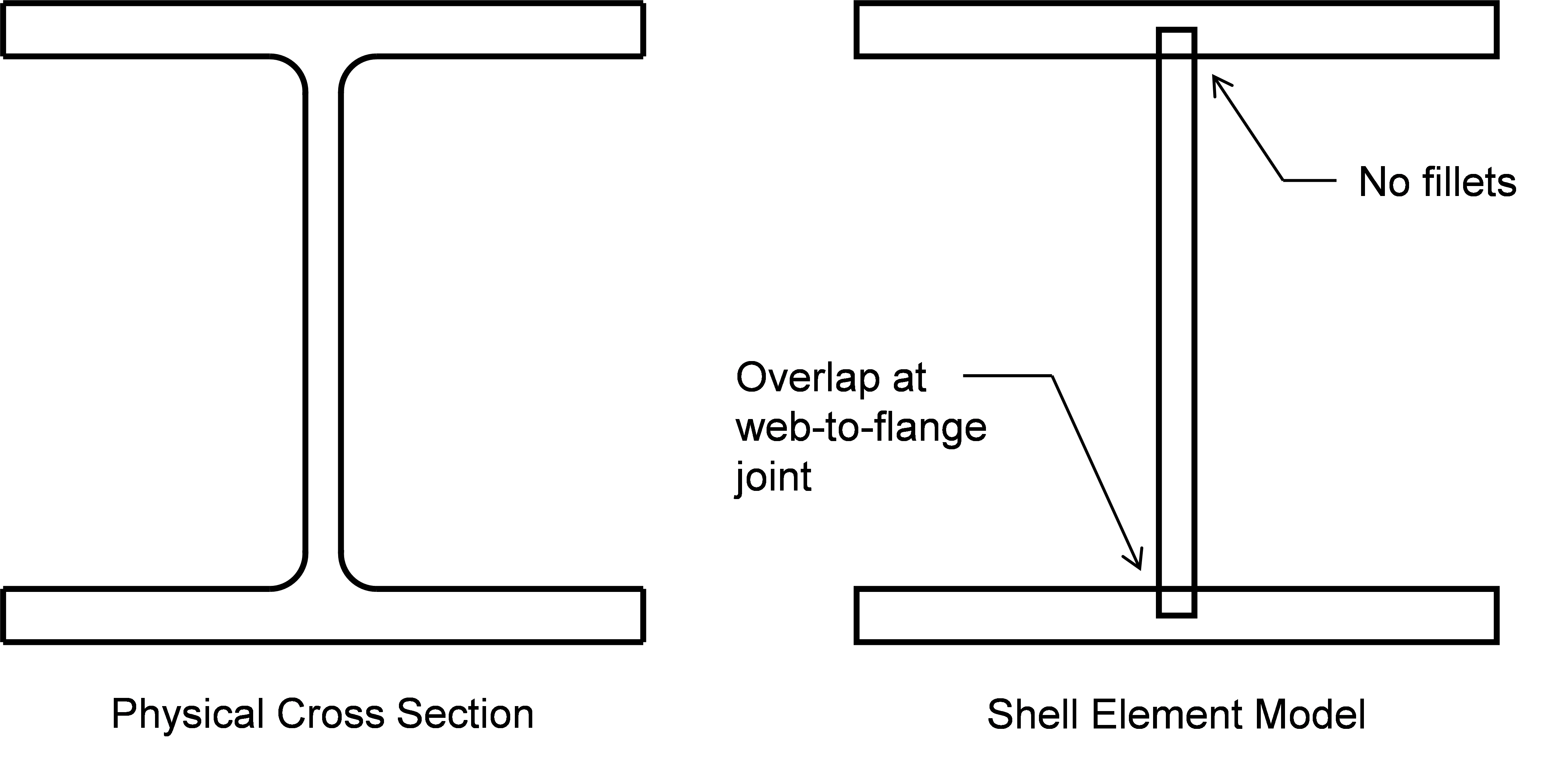
Elementele structurale din oțel sunt modelate cu elemente de tip placă în IDEA StatiCa, rezultând unele simplificări ale geometriei fizice. Elementele de tip placă reprezintă doar componente rectangulare, astfel că racordările sunt neglijate. În plus, deoarece elementele de tip placă sunt conectate în noduri situate la centrul grosimii, există o oarecare suprapunere la îmbinările elementelor secțiunii transversale. Figura de mai jos prezintă simplificările pentru un profil cu tălpi late. Simplificările cauzează mici diferențe în aria secțiunii transversale, care pot afecta rezistența la curgere prin întindere. Pentru un W14x159, aria secțiunii transversale listată în Tabelul 1-1 al Manualului AISC este de 46,7 in.2. Aria secțiunii transversale când este modelată ca în IDEA StatiCa este 2bftf+(d-tf)tw = 2(15,6 in.)(1,19 in) + (15,0 in. – 1,19 in.)(0,745 in.) = 47,4 in.2, unde dimensiunile secțiunii transversale au fost, de asemenea, determinate din Tabelul 1-1 al Manualului AISC. Aceasta reprezintă o diferență de 1,5%.
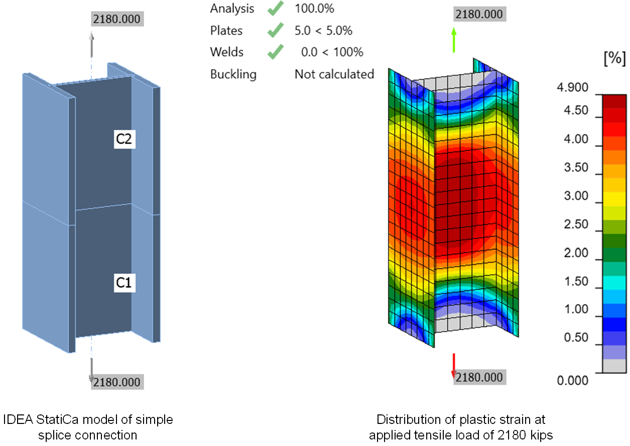
Efectul global al acestor diferențe minore poate fi observat într-un model simplu IDEA StatiCa al unei îmbinări de eclisare între două profile din oțel W14x159 (ASTM A992). Eclisarea este sudată cap la cap (de ex., CJP) și încărcată la întindere. Conform Specificației AISC (2022), rezistența de calcul a elementului din oțel solicitat la întindere cu profil cu tălpi late este 0,9×(50 ksi)×(46,7 in.2) = 2.100 kips. Sarcina maximă care poate fi aplicată îmbinării în IDEA StatiCa (versiunea 22.1) este de 2.180 kips, cu 4% mai mare decât rezistența de calcul calculată conform Specificației AISC. Distribuția deformației plastice în îmbinare arată că întreaga secțiune transversală a cedat.
Ruperea la Întindere
Prevederile pentru starea limită de rupere la întindere se află în Capitolul D al Specificației AISC. Aceste prevederi sunt referențiate în Secțiunea J4.1 a Specificației AISC pentru elementele de conectare. Rezistența nominală pentru ruperea la întindere se calculează ca rezistența la întindere a materialului, Fu, înmulțită cu aria netă efectivă, Ae. Aria netă efectivă ține cont de materialul eliminat, inclusiv găurile de șurub, și de efectul decalajului de forfecare prin factorul de decalaj de forfecare, U, definit în Tabelul D3.1 al Specificației AISC. Un factor de rezistență de ϕ = 0,75 este aplicat rezistenței nominale pentru a determina rezistența de calcul.
Starea limită de rupere la întindere nu este evaluată direct în IDEA StatiCa. Aceasta este captată prin limitarea cantității de deformație plastică pe care o poate experimenta orice componentă. Limita implicită de deformație plastică în IDEA StatiCa este de 5%. Nici Fu, nici factorul de rezistență de ϕ = 0,75 nu sunt utilizați în IDEA StatiCa. IDEA StatiCa utilizează o relație bilineară efort-deformație în care curgerea are loc la tensiunea de curgere a oțelului, Fy, înmulțită cu un factor de reducere egal cu 0,9 implicit (utilizatorul poate ajusta acest factor). După curgere, rigiditatea oțelului este doar o miime din modulul de elasticitate. Această rigiditate post-curgere este inclusă pentru stabilitate numerică și nu oferă nicio întărire semnificativă prin deformație. În plus, IDEA StatiCa nu utilizează factorii de decalaj de forfecare din Tabelul D3.1 al Specificației AISC. În schimb, decalajul de forfecare este modelat explicit.
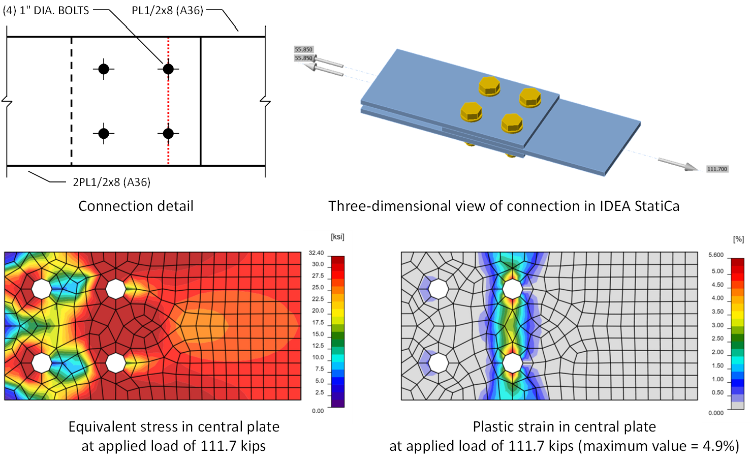
De asemenea, tensiunile care se dezvoltă în zonele de îmbinare sunt rareori pur uniaxiale. IDEA StatiCa utilizează criteriul de curgere von Mises pentru a identifica momentul în care apare curgerea sub aceste stări complexe de tensiune, ceea ce poate duce la o creștere aparentă a rezistenței. Pentru a ilustra acest efect, se consideră îmbinarea simplă de eclisare prezentată în figura de mai jos. Rezistența plăcii centrale în apropierea șuruburilor controlează rezistența acestei îmbinări. Pe baza procedurilor de calcul manual, s-ar putea aștepta că rezistența pe care IDEA StatiCa o va determina ar fi tensiunea la care apare curgerea înmulțită cu aria netă (indicată printr-o linie punctată roșie în figură). Pentru această îmbinare, aria netă este (1/2 in.)×(8 in. – 2dh) = 2,875 in.2, unde diametrul găurii, dh, este egal cu 1-1/8 in. (de remarcat că IDEA StatiCa nu include cei 1/16 in. pentru deteriorare descriși în Secțiunea B4.3b a Specificației AISC, a se vedea intrarea privind Determinarea Ariei Nete pentru informații suplimentare - ADD ANCHOR). Pentru LRFD, tensiunea la care apare curgerea în IDEA StatiCa este 0,9Fy și există o întărire minimă prin deformație (a se vedea intrarea privind Curgerea la Întindere pentru informații suplimentare). Pentru materialul A36 utilizat în acest exemplu, curgerea va apărea la 0,9(36 ksi) = 32,4 ksi. Prin urmare, s-ar putea aștepta că rezistența acestei îmbinări în IDEA StatiCa ar fi (2,875 in.2)×(32,4 ksi) = 93,1 kips. Cu toate acestea, deoarece tensiunea nu este pur uniaxială la secțiunea netă, celelalte componente de tensiune cresc efectiv tensiunea de curgere normală la aria netă, iar deformația plastică de 5% nu este atinsă până la o sarcină aplicată de 111,7 kips.
Luate individual, diferențele dintre calculele tradiționale și IDEA StatiCa rezultă în rezistențe mai mici în IDEA StatiCa (utilizând doar Fy și nu Fu), rezistențe mai mari în IDEA StatiCa (utilizând un factor de reducere a rezistenței materialului de 0,9 în loc de ϕ = 0,75) și rezistențe diferite în funcție de îmbinarea specifică (modelând explicit decalajul de forfecare în loc de utilizarea factorului de decalaj de forfecare, U). Luate împreună, diferențele duc de obicei, dar nu întotdeauna, la rezistențe egale sau mai mici din IDEA StatiCa față de calculele tradiționale.
Starea limită de rupere la întindere a fost investigată în acest studiu prin comparație cu sute de rezultate experimentale. Rezultatele arată că IDEA StatiCa este în general conservativă, în special la nivelul rezistenței nominale, dar există unele cazuri în care rezistența disponibilă din IDEA StatiCa este mai mare decât cea calculată conform Specificației AISC. Utilizând proprietăți măsurate ale materialului și geometriei fără factori de rezistență aplicați, rezistența din IDEA StatiCa a fost mai mică sau egală cu rezistența observată experimental pentru toți, cu excepția a 12 specimene din 529 (9 dintre care au fost fabricate din oțel de înaltă rezistență, Fy = 122,8 ksi) și mai mică sau egală cu rezistența așteptată la rupere prin întindere calculată folosind ecuațiile de proiectare pentru toți, cu excepția a 30 de specimene din 529. Utilizând proprietăți nominale ale materialului și geometriei cu factori de rezistență aplicați, rezistența din IDEA StatiCa a fost găsită a fi mai mare decât rezistența calculată conform Specificației AISC pentru unele îmbinări fără corespondent fizic, în special elemente din plăci solicitate la întindere cu suduri relativ scurte și elemente din HSS rectangular solicitate la întindere. Dat fiind că datele experimentale pentru aceste cazuri sunt limitate, lucrările sunt în curs pentru a determina dacă diferențele sunt rezultatul unui neconservatism în IDEA StatiCa sau al unui conservatism în ecuațiile Specificației AISC.
Curgerea la Compresiune și Flambaj
Rezistența disponibilă a elementelor afectate ale elementelor structurale și ale elementelor de conectare la compresiune este definită în Secțiunea J4.4 a Specificației AISC. Când raportul de zveltețe, Lc/r, este mai mic sau egal cu 25, se aplică curgerea la compresiune, iar rezistența nominală se calculează ca produsul dintre tensiunea minimă specificată de curgere și aria brută (adică, Pn = FyAg). Ca și pentru Curgerea la Întindere, starea limită de curgere la compresiune este evaluată în IDEA StatiCa cu limita de deformație plastică de 5%.
Când raportul de zveltețe, Lc/r, este mai mare de 25, se aplică prevederile Capitolului E al Specificației AISC. Stările limită din Capitolul E al Specificației AISC includ flambajul prin încovoiere, flambajul torsional și flambajul prin încovoiere-torsiune. Analiza neliniară efectuată în IDEA StatiCa este neliniară deoarece include efecte precum curgerea și contactul. Analiza nu ia în considerare de obicei neliniaritățile geometrice precum efectele P-Δ (neliniaritățile geometrice sunt luate în considerare când profilele HSS sunt utilizate ca elemente de reazem).
Inginerii trebuie să efectueze, de asemenea, o analiză liniară de flambaj pentru a detecta flambajul. O analiză liniară de flambaj poate determina sarcina elastică de flambaj, exprimată ca raport față de sarcina aplicată. Deși furnizează informații utile care pot ghida proiectarea, analiza liniară de flambaj nu ia în considerare curgerea potențială care poate reduce rigiditatea și sarcina de flambaj (adică, flambajul inelastic), nici nu ia în considerare efectele imperfecțiunilor geometrice inițiale. Din cauza acestor limitări, pentru a utiliza IDEA StatiCa, îmbinarea trebuie să fie suficient de compactă încât nici flambajul elastic, nici cel inelastic să nu apară. Raportul sarcinii elastice de flambaj oferă o măsură convenabilă a compacității (sau zvelteței).
Se consideră limita raportului de zveltețe din Secțiunea J4.4 a Specificației AISC de Lc/r ≤ 25 pentru a presupune curgerea la compresiune. Un raport de zveltețe de Lc/r = 25 corespunde unei tensiuni critice elastice Fe = π2E/(Lc/r)2 = π2(29.000 ksi)/(25)2 = 458 ksi. Pentru oțelul A36, aceasta corespunde de 14 ori tensiunii de curgere factorizate pentru LRFD și de 21 de ori pentru ASD. Pentru oțelul de grad 50, tensiunea critică elastică corespunde de 10 ori tensiunii de curgere factorizate pentru LRFD și de 15 ori pentru ASD. În consecință, raportul sarcinii elastice de flambaj trebuie menținut mai mare decât aceste rapoarte pentru a evita cazurile în care flambajul inelastic ar putea fi determinant.
Limita adecvată a raportului sarcinii elastice de flambaj variază în funcție de configurația îmbinării. Pentru flambajul plăcilor, limita este mult mai mică. Pe baza limitelor de lățime-grosime din Tabelul B4.1a al Specificației AISC, raportul sarcinii critice de flambaj elastic trebuie menținut la cel puțin 3 pentru LRFD și 4,5 pentru ASD. O evaluare a plăcilor de consolă a identificat limite ale raportului sarcinii critice de flambaj elastic de 4 pentru LRFD și 6 pentru ASD. Utilizarea unei limite a raportului sarcinii critice de flambaj de 3 a fost evaluată pentru elementele de rigidizare de reazem (raport în curs de elaborare), grinzi cu inimă decupată și îmbinări grindă-peste-stâlp.
Elementele îmbinărilor care sunt suficient de zvelte pentru ca flambajul inelastic să apară au totuși rezistență, potențial suficientă pentru o aplicație dată. Cu toate acestea, fără capacitatea de a cuantifica cu precizie rezistența la flambaj inelastic în IDEA StatiCa, aceste cazuri trebuie evitate.
Curgerea și Ruperea la Forfecare
Rezistența disponibilă a elementelor afectate ale elementelor structurale și ale elementelor de conectare la forfecare este definită în Secțiunea J4.2 a Specificației AISC. Această secțiune descrie două stări limită: curgerea la forfecare și ruperea la forfecare. Pentru ambele stări limită, IDEA StatiCa nu calculează rezistența disponibilă conform Specificației AISC, ci se bazează pe limita de deformație plastică de 5% pentru a evalua dacă îmbinarea este suficient de rezistentă.
La întindere, relația efort-deformație utilizată în IDEA StatiCa este liniară până la curgere, cu o rigiditate egală cu modulul de elasticitate, apoi liniară după aceea, cu o rigiditate egală cu o miime din modulul de elasticitate. Curgerea la întindere apare la tensiunea minimă specificată de curgere a oțelului, Fy, înmulțită cu 0,9 pentru LRFD sau împărțită la 1,67 pentru ASD. IDEA StatiCa utilizează criteriul de curgere von Mises pentru a determina când începe curgerea sub stări multiaxiale de tensiune. Conform criteriului de curgere von Mises, materialul supus la forfecare pură va curge când tensiunea de forfecare este egală cu tensiunea de curgere împărțită la rădăcina pătrată din 3. Inversul rădăcinii pătrate din 3 este aproximativ egal cu 0,577, ceea ce este aproximativ egal cu factorul 0,6 aplicat ecuațiilor de rezistență la forfecare din Specificația AISC. Această diferență, sau diferențe similare când elementul nu este strict în forfecare pură, poate duce la diferențe între IDEA StatiCa și calculele tradiționale. Mica cantitate de întărire prin deformație poate duce, de asemenea, la diferențe, după cum este descris în intrarea privind Curgerea la Întindere.
Diferențe pot apărea și deoarece în Secțiunea J4.2 a Specificației AISC, factorul de rezistență pentru curgerea la forfecare este definit ca 1,00, iar factorul de siguranță pentru curgerea la forfecare este definit ca 1,50. IDEA StatiCa nu utilizează acești factori și în schimb reduce punctul de curgere cu un factor de 0,9 pentru LRFD sau prin împărțire la 1,67 pentru ASD, pe baza factorului tipic de rezistență și a factorului de siguranță pentru curgere.
Alte diferențe există pentru starea limită de rupere la forfecare. Așa cum este descris pentru starea limită de Rupere la Întindere, IDEA StatiCa nu utilizează rezistența la întindere a oțelului, Fu, nici factorul de rezistență sau factorul de siguranță pentru ruperea la forfecare. Din nou, punctul de curgere la întindere este luat ca 0,9Fy pentru LRFD și Fy/1,67 pentru ASD. Rezultatul acestor diferențe depinde de raportul rezistențelor materialului. De asemenea, în îmbinările cu șuruburi, aria netă supusă forfecării trece de obicei prin axele centrale ale șuruburilor. Distribuția deformațiilor plastice la punctul limită în IDEA StatiCa poate fi diferită, după cum s-a observat pentru îmbinările cu placă de inimă la forfecare în acest articol.
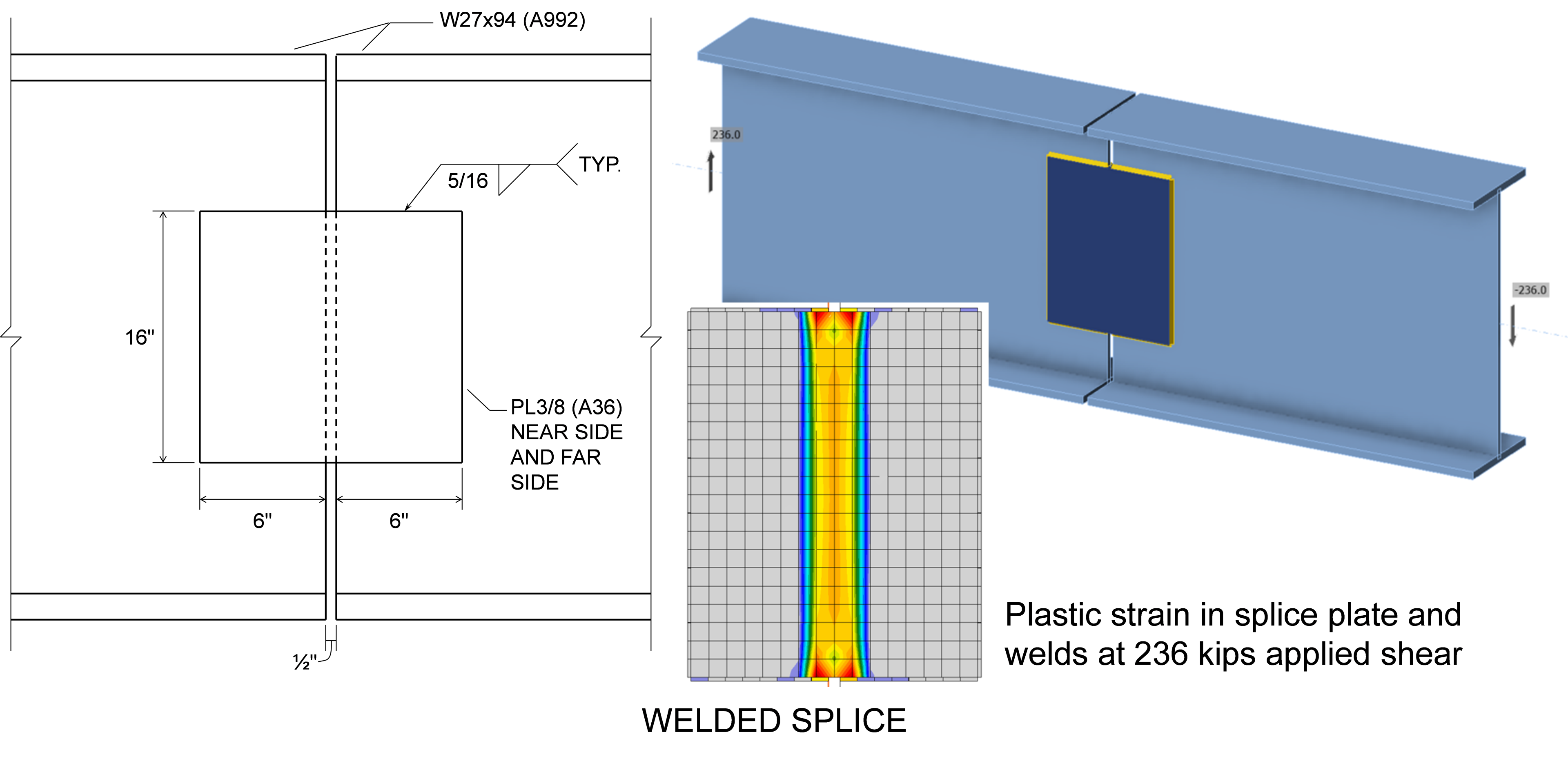
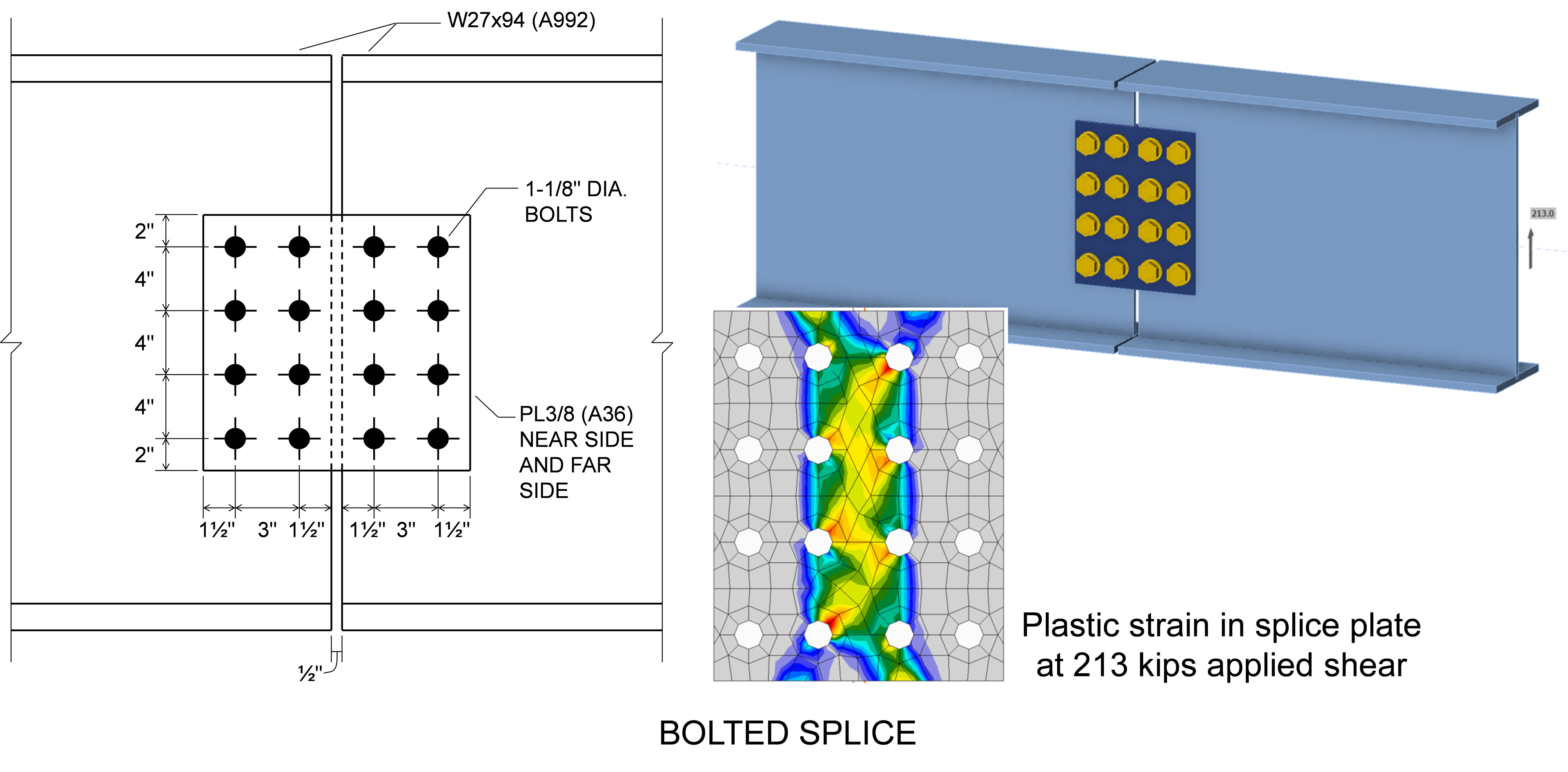
Ca exemplu al rezultatului combinat al diferențelor dintre ecuațiile Specificației AISC și IDEA StatiCa, se consideră cele două îmbinări de eclisare a grinzilor prezentate în figurile de mai jos. Pentru ambele, două grinzi W27×94 din oțel A992 sunt conectate prin plăci de eclisare pe ambele părți ale inimii. Plăcile de eclisare au grosimea de 3/8 in. și sunt din oțel A36.
Îmbinarea sudată este controlată de curgerea la forfecare a plăcilor de eclisare. Rezistența de calcul pentru plăci este ϕRn = ϕ0,6FyAgv = (1,0)0,6(36 ksi)(2 × 3/8 in. × 16 in.) = 259 kips. În IDEA StatiCa, plăcile de eclisare ating o deformație plastică de 5% când sunt supuse la o sarcină de forfecare de 236 kips. Diferența de rezistențe se datorează în principal utilizării ϕ = 1,0 în ecuațiile Specificației AISC și a unei reduceri de 0,9 asupra tensiunii de curgere în IDEA StatiCa.
Îmbinarea cu șuruburi este controlată de ruperea la forfecare a plăcilor de eclisare. Rezistența de calcul pentru plăci este ϕRn = 210 kips. În IDEA StatiCa, plăcile de eclisare ating o deformație plastică de 5% când sunt supuse la o sarcină de forfecare de 213 kips, aproape aceeași cu rezistența de calcul conform Specificației AISC, indicând că diferențele se contracarează reciproc și rezultă într-un proiect sigur.
Curgerea sub Acțiuni Combinate
Elementele structurale și elementele de conectare sunt adesea supuse la mai multe acțiuni simultan, inclusiv forță axială, moment încovoietor, forfecare și torsiune. Secțiunea J4 a Specificației AISC nu furnizează cerințe specifice pentru elementele de conectare supuse la acțiuni combinate. Cu toate acestea, Partea 9 a Manualului AISC descrie mai multe abordări pentru evaluarea elementelor de conectare supuse la acțiuni combinate. O abordare constă în suprapunerea tensiunilor calculate pe baza teoriei elastice a grinzilor și utilizarea unui criteriu de primă curgere. O altă abordare constă în utilizarea ecuațiilor de interacțiune care aproximează limita rezistenței plastice. O astfel de ecuație care se aplică elementelor rectangulare sub încărcare în plan este Ecuația 9-1 din Manualul AISC.
\[ \frac{M_r}{M_c} + \left ( \frac{P_r}{P_c} \right )^2 + \left ( \frac{V_r}{V_c} \right )^4 \le 1.0 \]
unde Mr, Pr și Vr sunt rezistențele solicitate la încovoiere, axiale și la forfecare, respectiv; iar Mc, Pc și Vc sunt rezistențele disponibile la încovoiere, axiale și la forfecare, respectiv.
Dowswell (2015) a prezentat o ecuație mai generală pentru elementele rectangulare sub încărcare în plan și în afara planului.
\[ \left ( \frac{P_r}{P_c} \right )^2 + \left ( \frac{T_r}{T_c} \right )^2 + \left ( \frac{V_r}{V_c} \right )^4 + \left ( \left ( \frac{M_{rx}}{M_{cx}} \right )^{1.7} + \left ( \frac{M_{ry}}{M_{cy}} \right )^{1.7} \right )^{0.59} \le 1.0 \]
unde Tr, Mrx și Mry sunt rezistențele solicitate la torsiune, la încovoiere față de axa principală și la încovoiere față de axa secundară, respectiv; iar Tc, Mcx și Mcy sunt rezistențele disponibile la torsiune, la încovoiere față de axa principală și la încovoiere față de axa secundară, respectiv.
În IDEA StatiCa, elementele de conectare sunt modelate cu elemente finite de tip placă cărora li se atribuie un model de material cu plasticitate multiaxială care utilizează criteriul de curgere von Mises (utilizarea criteriului de curgere von Mises este descrisă și în Partea 9 a Manualului AISC). Pe măsură ce sarcina este aplicată în model, elementele individuale de tip placă experimentează stări generale de tensiune care sunt evaluate folosind criteriul pentru a determina dacă a apărut curgerea. Dacă apare curgerea, rigiditatea materialului este redusă la 1/1000 din rigiditatea inițială și analiza continuă.
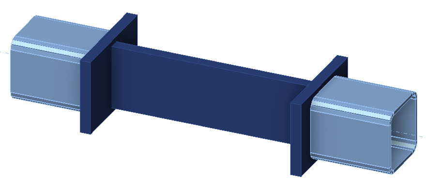
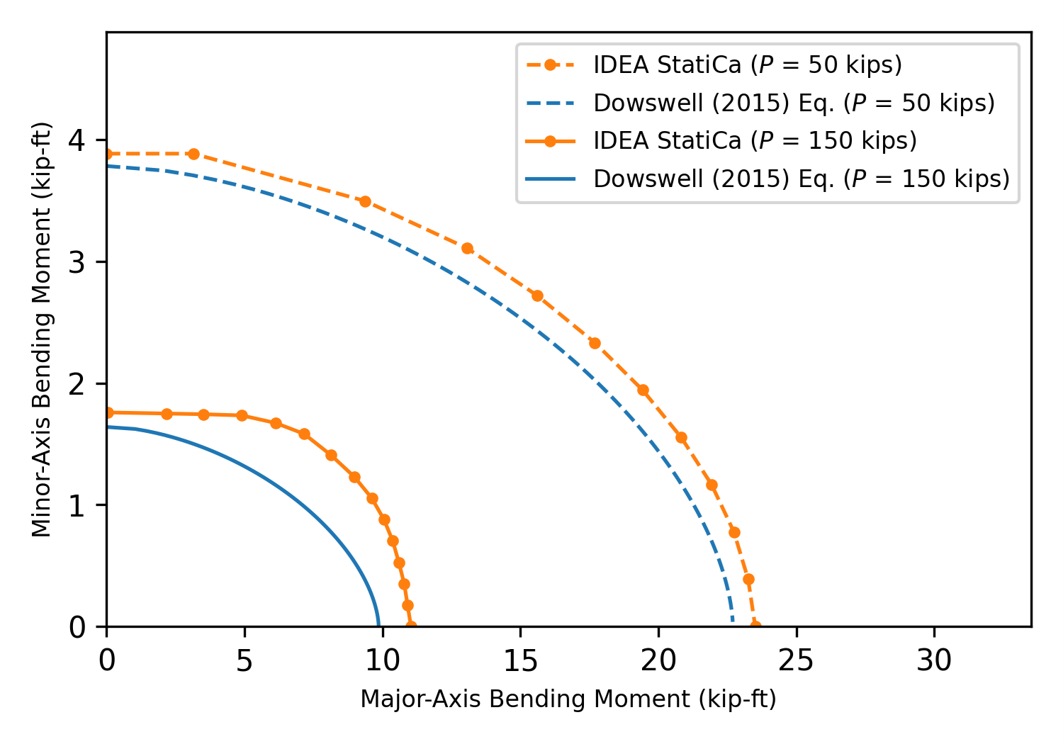
Pentru a ilustra diferențele dintre rezistențele calculate folosind ecuațiile de interacțiune și IDEA StatiCa, se consideră îmbinarea prezentată mai jos. Placa centrală de „test" are o grosime de 1 in., o înălțime de 6 in., o lungime de 10 in. și este din oțel A36. Atât plăcile de conectare, cât și elementele din profile tubulare au fost selectate pentru a fi rezistente și rigide. Analizele au fost efectuate supunând placa de test la încărcare biaxială, constând din întindere axială și moment încovoietor față de axele principale și secundare, pentru a determina sarcinile aplicate maxime admise (adică sarcinile care cauzează o deformație plastică de 5% în placa de test). Pentru aceste analize, opțiunea geometrică neliniară (GMNA) a fost dezactivată în configurarea codului. De asemenea, dimensiunea maximă a elementelor a fost modificată la 0,25 in. și dimensiunea minimă a elementelor a fost modificată la 0,10 in. pentru a crea o plasă mai fină și a capta distribuția tensiunilor mai precis.
Rezultatele analizelor IDEA StatiCa sunt prezentate în figura de mai jos. Diagramele de interacțiune bazate pe ecuația Dowswell (2015) sunt, de asemenea, prezentate în figură. Rezistențele disponibile utilizate pentru diagramele de interacțiune calculate sunt Pc = ϕPn = 194,4 kips, Mcx = ϕMnx = 24,3 kip-ft și Mcy = ϕMny = 4,05 kip-ft. Se observă diferențe între rezultatele IDEA StatiCa și cele din ecuația de interacțiune, inclusiv când se aplică o singură acțiune. Cauzele diferențelor sub o singură acțiune sunt descrise în intrările privind curgerea la încovoiere și curgerea la întindere. Diferențele dintre IDEA StatiCa și ecuația aproximativă pentru acțiuni combinate sunt mai mari, dar rezultatele IDEA StatiCa arată efecte clare de interacțiune.
Ruperea prin Forfecare în Bloc
Ruperea prin forfecare în bloc este o cedare combinată la întindere și forfecare în care un bloc de material este smuls dintr-un element structural sau de conectare. Rezistența disponibilă pentru starea limită de rupere prin forfecare în bloc este definită în Secțiunea J4.3 a Specificației AISC. Ca și pentru starea limită de rupere la întindere, starea limită de rupere prin forfecare în bloc nu este evaluată direct în IDEA StatiCa. Aceasta este captată prin limitarea cantității de deformație plastică pe care o poate experimenta orice componentă la maximum 5% (utilizatorul poate modifica această limită). Diferențele cheie dintre calculele tradiționale și IDEA StatiCa rezultă din relația efort-deformație utilizată în IDEA StatiCa. Este inclusă doar o întărire minimă post-curgere (adică, tensiunile nu ating Fu), iar tensiunea de curgere este redusă cu 0,9 pentru LRFD (adică, nu ϕ = 0,75 conform specificației pentru ruperea prin forfecare în bloc).
O comparație între calculele tradiționale și IDEA StatiCa pentru starea limită de rupere prin forfecare în bloc în îmbinările cu șuruburi este prezentată în acest articol. Rezultatele comparației arată că rezistența din IDEA StatiCa poate fi mai mare decât cea conform Specificației AISC pentru unele cazuri, în special dacă raportul dintre rezistența la întindere și tensiunea de curgere (Fu/Fy) este relativ scăzut. Cu toate acestea, cercetătorii au identificat că prevederile Specificației AISC pot fi conservative în comparație cu rezultatele experimentale. Rezistența la rupere prin forfecare în bloc din IDEA StatiCa a fost găsită a fi precisă sau conservativă în comparație cu standardul canadian (CSA S16) și o ecuație de proiectare alternativă propusă de cercetători.
Rezistența pentru starea limită de rupere prin forfecare în bloc în IDEA StatiCa poate varia în funcție de tipul de transfer al forței de forfecare al șuruburilor. În IDEA StatiCa, forțele sunt transferate de la o placă la alta pe o suprafață mai mare pentru îmbinările rezistente la alunecare decât pentru îmbinările de tip presiune de contact. Distribuția mai largă a forțelor de transfer, deși reprezentativă fizic pentru transferul de sarcină prin frecare, poate duce la căi diferite de cedare prin rupere în bloc și la o rezistență crescută. Pentru majoritatea îmbinărilor, rezistența la alunecare este mai mică decât rezistența la rupere prin forfecare în bloc. Cu toate acestea, deoarece îmbinările rezistente la alunecare trebuie proiectate și pentru stările limită ale îmbinărilor de tip presiune de contact, pe lângă alunecare (Secțiunea J3.9 a Specificației AISC), se recomandă ca îmbinările rezistente la alunecare să fie analizate de două ori în IDEA StatiCa: o dată ca îmbinare rezistentă la alunecare (adică, cu tipul de transfer al forței de forfecare setat pe „Friction") și din nou ca îmbinare de tip presiune de contact (adică, cu tipul de transfer al forței de forfecare setat pe „Bearing – tension/shear interaction").
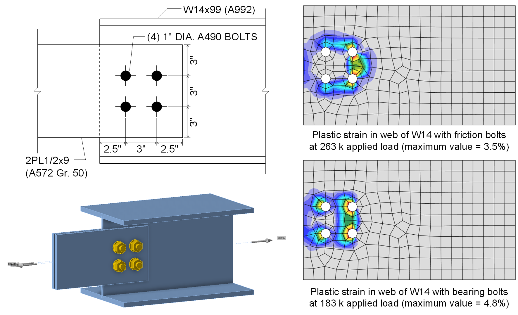
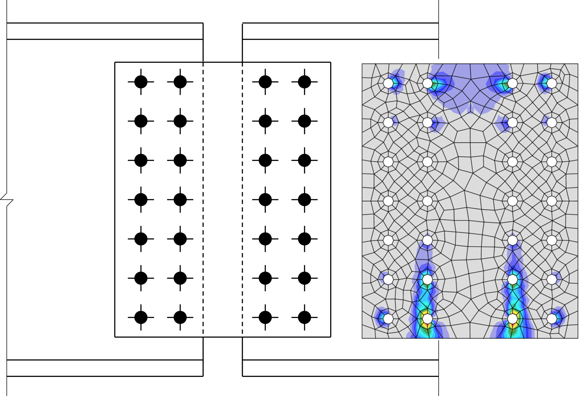
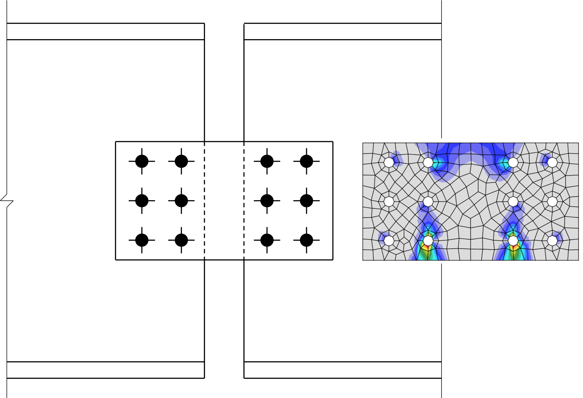
Pentru a ilustra acest efect, se consideră îmbinarea prezentată mai jos între un element W14x99 (A992) solicitat la întindere și două plăci. Îmbinarea este realizată cu (4) șuruburi A490 cu diametrul de 1 in. în găuri standard și suprafețe de Clasa B. Rezistența de calcul a acestei îmbinări pentru starea limită de alunecare este \(\phi R_n = 289\textrm{ kips}\), însă ruperea prin forfecare în bloc controlează rezistența îmbinării cu o rezistență de calcul de \(\phi R_n = 148 \textrm{ kips}\). Când este modelată în IDEA StatiCa și tipul de transfer al forței de forfecare al șuruburilor este setat pe „Friction", pot fi aplicate sarcini de până la 263 kips înainte ca gradul de utilizare al șuruburilor să atingă 100%. Diferența dintre această rezistență și rezistența de calcul de 289 kips pentru starea limită de alunecare se datorează faptului că întinderea în șuruburi se dezvoltă în model și este tratată conservativ ca o întindere aplicată în IDEA StatiCa. La 263 kips de întindere aplicată și utilizând șuruburi „Friction", deformația plastică în inimă este de 3,5%, sub limita de 5%. Când tipul de transfer al forței de forfecare pentru șuruburi este setat pe „Bearing – tension/shear interaction", sarcina maximă aplicată scade la 183 kips, cu deformația plastică în inimă ca factor de control. Diferența dintre această rezistență și rezistența de calcul de 148 kips pentru starea limită de rupere prin forfecare în bloc este predominant conservatismul din ecuația Specificației AISC pentru ruperea prin forfecare în bloc, după cum este descris în acest articol. Conform standardului canadian (CSA S16), rezistența de calcul a acestei îmbinări pentru starea limită de rupere prin forfecare în bloc este de 181 kips, aproximativ egală cu rezistența din IDEA StatiCa. Figura de mai jos prezintă deformația plastică în inimă la sarcina maximă aplicată pentru fiecare tip de transfer al forței de forfecare. Distribuțiile deformației plastice sunt clar diferite și demonstrează distribuția mai largă a forțelor de transfer pentru șuruburile „Friction" în IDEA StatiCa. Discuții suplimentare pot fi găsite în intrarea privind Alunecarea.
Curgerea la Încovoiere
Rezistența nominală pentru curgerea la încovoiere este definită în Capitolul F al Specificației AISC (2022) pentru elementele solicitate la încovoiere și în Secțiunea J4.5 pentru elementele de conectare. Rezistența nominală pentru starea limită de curgere la încovoiere este în general luată ca tensiunea minimă specificată de curgere, Fy, înmulțită cu modulul de rezistență plastic, Z. În IDEA StatiCa, în loc să limiteze rezistența solicitată la cel mult rezistența disponibilă (de ex., Mu ≤ ϕMn), elementele structurale și elementele de conectare sunt modelate cu elemente de tip placă cărora li se atribuie o relație neliniară efort-deformație constând dintr-o regiune liniară elastică și o regiune liniară plastică, iar deformația plastică este limitată la 5%.
Modelarea elementelor structurale și a elementelor de conectare ca elemente de tip placă rezultă în unele simplificări ale geometriei fizice. De exemplu, elementele de tip placă reprezintă doar componente rectangulare, astfel că racordările sunt neglijate. În plus, deoarece elementele de tip placă sunt conectate în noduri situate la centrul grosimii, există o oarecare suprapunere la îmbinările elementelor secțiunii transversale. Figura de mai jos prezintă simplificările pentru un profil cu tălpi late.

Profil cu tălpi late modelat în IDEA StatiCa
Pentru un W24x176, modulul de rezistență plastic față de axa principală (axa x) listat în Manualul de Construcții din Oțel AISC (2023) Tabelul 1-1 este de 511 in.3. Modulul de rezistență plastic față de axa principală a secțiunii transversale formate de elementele de tip placă (cu dimensiunile secțiunii transversale determinate din Tabelul 1-1 al Manualului AISC) se calculează după cum urmează:
\[\frac{t_w(d-t_f)^2}{4}+2b_f t_f \left ( \frac{d-t_f}{2} \right ) = \frac{0.75 \textrm{ in.}(25.2 \textrm{ in.}-1.34\textrm{ in.})^2}{4}+2(12.9\textrm{ in.}) (1.34\textrm{ in.}) \left ( \frac{25.2\textrm{ in.}-1.34\textrm{ in.}}{2} \right ) = 519.2 \textrm{ in.}^3\]
Aceasta este cu 1,6% mai mare decât modulul de rezistență plastic listat în tabelul Manualului AISC.
Distribuția tensiunilor la limita de deformație plastică în IDEA StatiCa va fi, de asemenea, diferită față de distribuția idealizată a tensiunilor utilizată pentru calculul Mp. Spre deosebire de distribuția idealizată a tensiunilor, tensiunile vor fi mai mici decât Fy în apropierea axei neutre, deoarece limita de deformație plastică va fi atinsă la o curbură finită. De asemenea, tensiunile vor fi mai mari decât Fy la fibrele extreme ale secțiunii transversale, deoarece o mică cantitate de întărire post-curgere este presupusă în relația efort-deformație din IDEA StatiCa.
Efectul global al acestor diferențe minore poate fi observat într-o îmbinare simplă de eclisare între două profile din oțel W24x176 (ASTM A992). Eclisarea este sudată cap la cap (de ex., CJP) și încărcată la încovoiere față de axa principală. Rezistența de calcul a profilului cu tălpi late conform Specificației AISC (2022) cu factorul de rezistență, ϕ = 0,9, este 0,9 × 50 ksi × 511 in.3 = 1916,3 kip-ft. Momentul maxim care poate fi aplicat îmbinării în IDEA StatiCa (versiunea 23.0) este de 2000,7 kip-ft., cu 4,4% mai mare decât rezistența de calcul calculată conform Specificației AISC. Distribuția deformației plastice la limită este prezentată în figura de mai jos. Conform așteptărilor, tălpile superioare și inferioare au cedat, dar inima la axa neutră rămâne elastică.
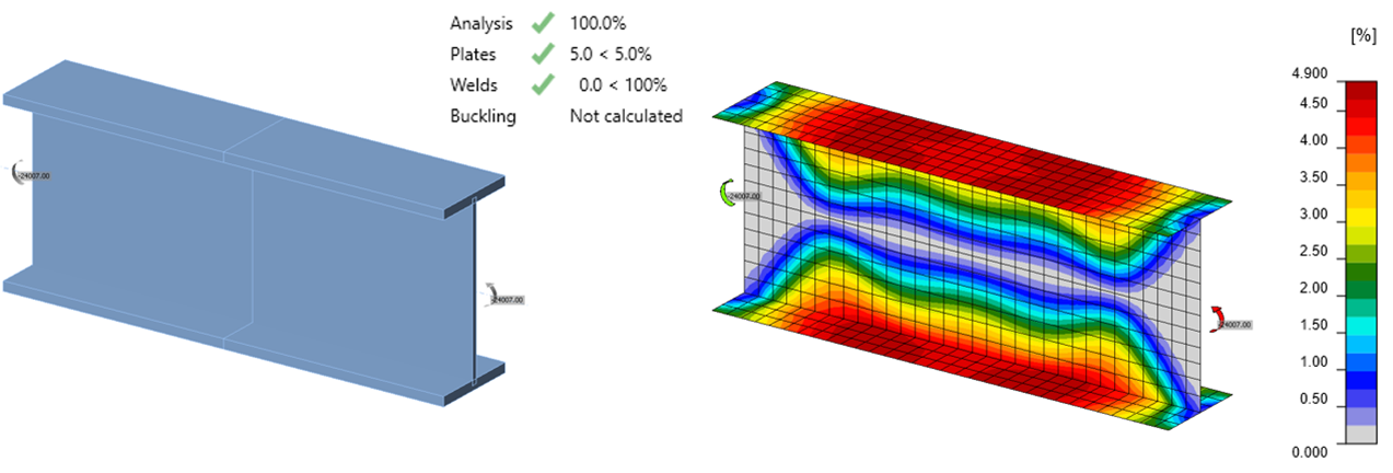
Distribuția deformației plastice pentru un element încovoiat W24x176 la limita de deformație plastică de 5%
Relația dintre momentul aplicat și deformația plastică maximă este prezentată în figura de mai jos. Rezistența la încovoiere de calcul calculată folosind modulul de rezistență plastic din Manualul AISC este prezentată ca ϕMp (Manual). Rezistența la încovoiere de calcul calculată folosind modulul de rezistență plastic calculat după cum se arată mai sus, pe baza reprezentării secțiunii în IDEA StatiCa, este prezentată ca ϕMp (IDEA).
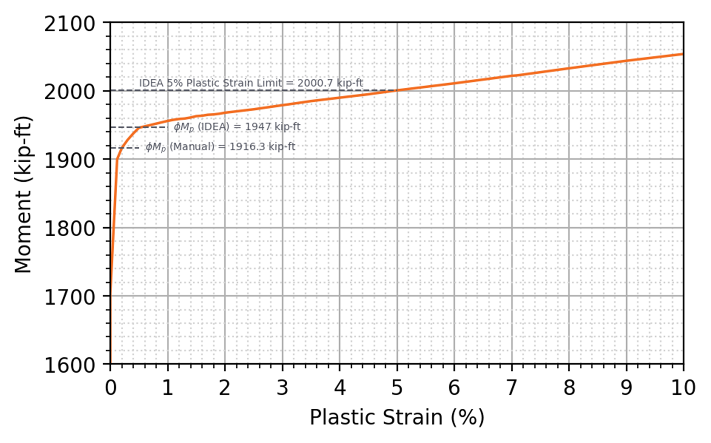
Momentul aplicat față de deformația plastică pentru un element încovoiat W24x176
Pentru o grindă cu profil cu tălpi late, cea mai mare parte a rezistenței la încovoiere este captată de comportamentul în plan al elementelor de tip placă. Comportamentul în afara planului al elementelor de tip placă poate fi evaluat printr-o investigare a încovoierii plăcilor.
Pentru o placă (ASTM A36, Fy = 36 ksi) cu lățimea, b = 10 in. și grosimea, t = 0,5 in., modulul de rezistență plastic pentru încovoierea în afara planului se calculează ca Z = bt2/4 = 0,625 in.3, iar rezistența de calcul, ϕMp, cu factorul de rezistență, ϕ = 0,9, se calculează ca 0,9 x 36 ksi x 0,625 in.3 = 20,25 kip-in. Simplificările geometrice descrise mai sus pentru o secțiune cu profil cu tălpi late nu se aplică unei plăci rectangulare simple, dar diferențele în distribuția tensiunilor rămân. Momentul maxim care poate fi aplicat plăcii în IDEA StatiCa (versiunea 23.0) este de 19,66 kip-in., cu 2,9% mai mic decât rezistența de calcul calculată conform Specificației AISC. Distribuția deformației plastice pentru placa încărcată la încovoiere față de axa secundară și un grafic al momentului aplicat față de deformația plastică sunt prezentate în figurile de mai jos.
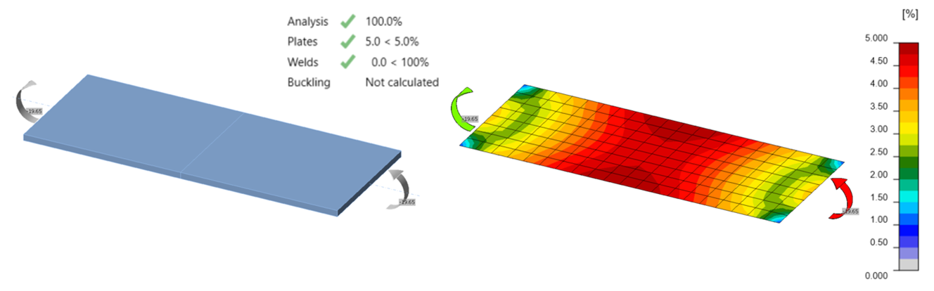
Distribuția deformației plastice pentru încovoierea plăcii în afara planului la limita de deformație plastică de 5%
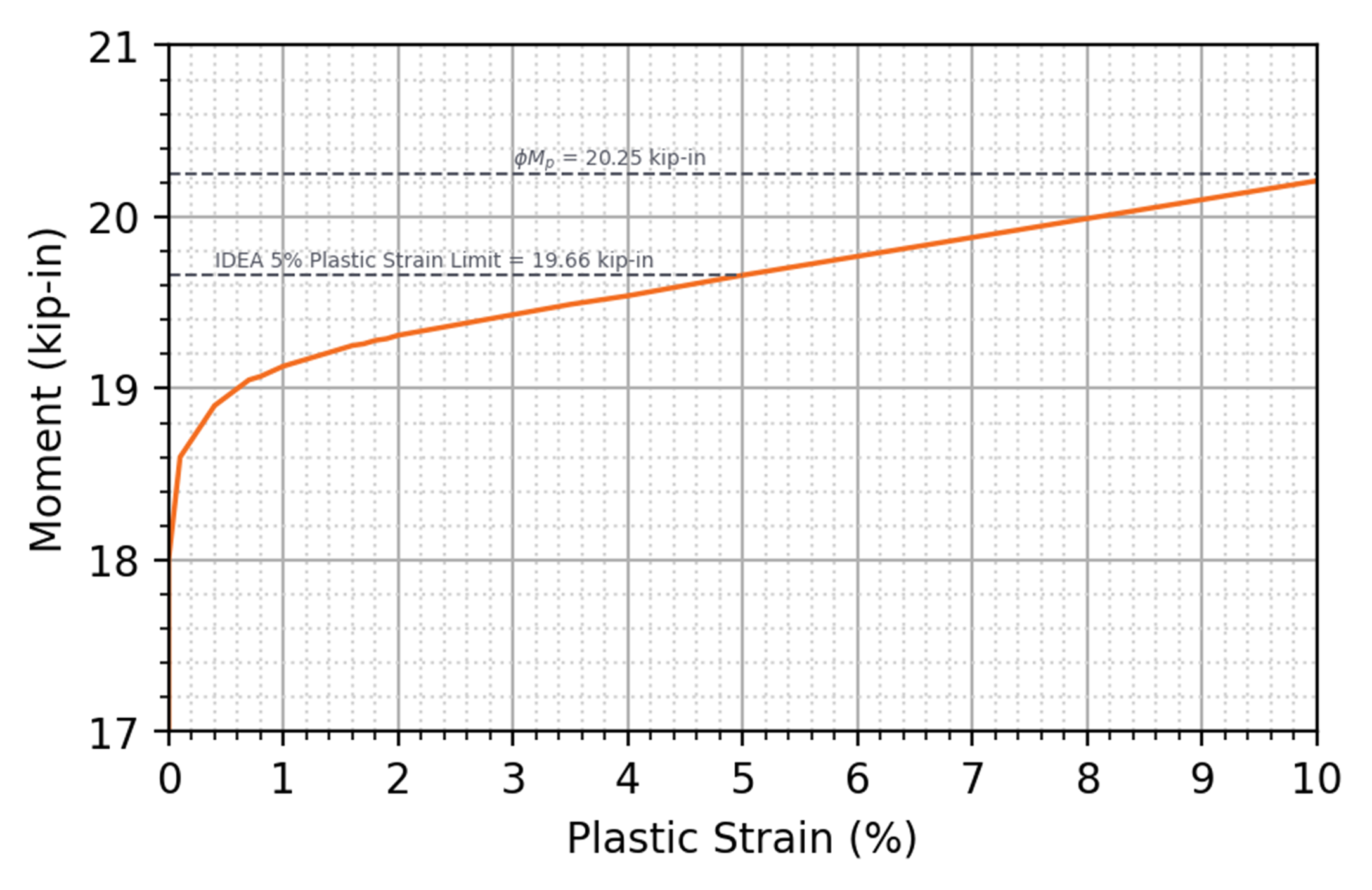
Momentul aplicat față de deformația plastică pentru o placă încărcată la încovoiere față de axa secundară
Ruperea la Încovoiere
Ruperea la încovoiere este una dintre stările limită identificate pentru elementele afectate ale elementelor structurale și ale elementelor de conectare solicitate la încovoiere în Secțiunea J4.5 a Specificației AISC. Ruperea la încovoiere poate apărea când un moment este aplicat unei secțiuni transversale cu material eliminat, cum ar fi găurile de șurub. Capitolul J al Specificației AISC nu definește rezistența disponibilă pentru starea limită de rupere la încovoiere. Secțiunea F13.1 a Specificației AISC abordează ruperea la încovoiere pentru elementele cu găuri de șurub în talpa întinsă, iar îndrumări sunt furnizate pentru ruperea la încovoiere a elementelor afectate și de conectare în Partea 9 a Manualului AISC. În mod specific, Ecuația 9-8 din Manualul AISC definește rezistența nominală pentru ruperea la încovoiere ca produsul dintre rezistența minimă specificată la întindere și modulul de rezistență plastic net al elementului afectat sau de conectare. Manualul AISC definește în continuare factorul de rezistență ca \(\phi=0.75\) și factorul de siguranță ca \(\Omega = 2.00\) pentru ruperea la încovoiere.
Ca și pentru starea limită de rupere la întindere, IDEA StatiCa nu evaluează ecuațiile de rezistență pentru ruperea la încovoiere. În schimb, starea limită de rupere la încovoiere este evaluată folosind limita de deformație plastică. Astfel, ca și pentru ruperea la întindere, diferențele apar deoarece relația efort-deformație utilizată în IDEA StatiCa are o întărire minimă prin deformație după curgere, în timp ce ecuația de proiectare utilizează rezistența la întindere a materialului, și deoarece IDEA StatiCa reduce tensiunea la curgere cu un factor de 0,9 (pentru LRFD), în timp ce un factor de rezistență de 0,75 este utilizat pentru ruperea la încovoiere. Diferențe suplimentare, specifice ruperii la încovoiere, rezultă din utilizarea unui modul de rezistență plastic în ecuația de proiectare, care presupune o tensiune uniformă fie la întindere, fie la compresiune. În IDEA StatiCa, tensiunile sunt rezultate ale analizei și nu sunt neapărat uniforme.
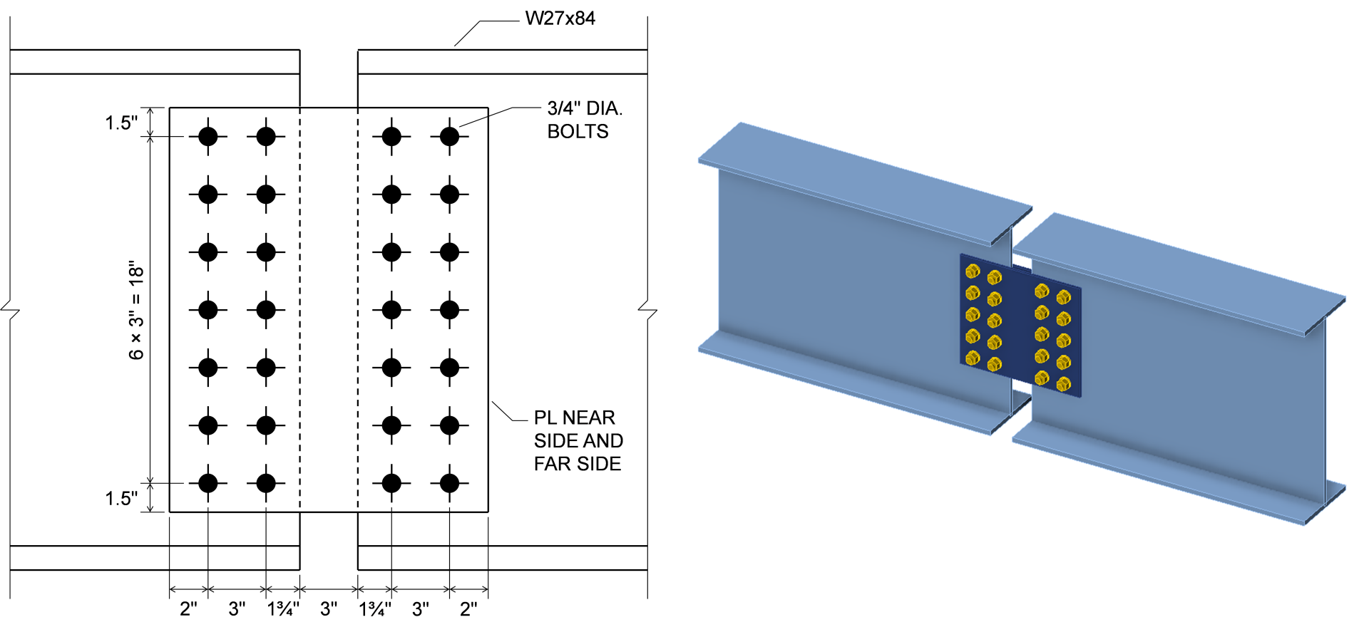
Pentru a examina efectul net al acestor diferențe, se consideră plăcile de eclisare testate de Mohr și Murray (2008). Aceștia au testat în total 14 specimene; cele șase teste din prima serie cu trei tipare diferite de șuruburi sunt investigate aici. Plăcile au fost instalate între două grinzi W27x84. Ansamblul întreg a fost încărcat la încovoiere în patru puncte, supunând placa la încovoiere pură. Dimensiunile celor mai mari plăci, cele cu 7 șuruburi în fiecare rând vertical, sunt prezentate mai jos. Testele au fost efectuate și cu 5 și 3 șuruburi în fiecare rând vertical cu dimensiuni similare. Tensiunea de curgere măsurată a plăcilor a fost Fy = 49,5 ksi, rezistența la întindere măsurată a plăcilor a fost Fu = 72,1 ksi, iar grosimea măsurată a plăcilor a fost t = 0,370 in.
Rezistența de calcul, \(\phi M_n\), a plăcilor a fost calculată conform Specificației AISC pentru starea limită de curgere la încovoiere și conform Manualului AISC pentru starea limită de rupere la încovoiere. Proprietățile măsurate ale materialului și geometriei au fost utilizate în aceste calcule, iar factorii de rezistență au fost aplicați. Modele IDEA StatiCa ale celor trei îmbinări au fost, de asemenea, construite folosind proprietățile măsurate ale materialului și geometriei plăcilor. Factorii de rezistență au rămas la valorile lor implicite. Proprietățile grinzilor și șuruburilor au fost crescute față de valorile nominale pentru a asigura că modul de cedare corespunde celui din experiment. Momentul aplicat maxim admis din IDEA StatiCa, MIDEA, a fost determinat iterativ. Rezultatele acestor calcule sunt prezentate în figura de mai jos împreună cu rezistența experimentală, Mexp. Rezistența experimentală a fost luată ca media rezistențelor raportate pentru cele două specimene ale fiecărui tipar de șuruburi. Momentele din figură sunt pentru fiecare placă, menționând că au existat două plăci pentru fiecare specimen, câte una pe fiecare parte a grinzilor.
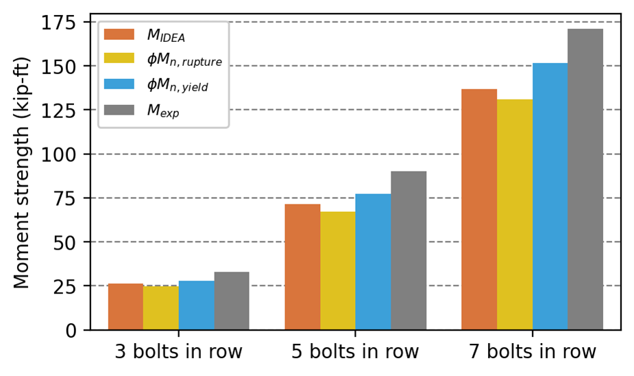
În experimentele fizice, toate specimenele au cedat prin rupere la încovoiere. Ruperea la încovoiere controlează, de asemenea, rezistența la moment a plăcilor deoarece \(\phi M_{n,rupture} < \phi M_{n,yield}\). IDEA StatiCa, însă, nu distinge clar între aceste două stări limită; ambele sunt evaluate folosind limita de deformație plastică de 5%. Deformația plastică în plăci la sarcina aplicată maximă admisă este prezentată pentru cazurile cu 7 și 3 șuruburi în fiecare rând vertical mai jos.
Momentul aplicat maxim admis din IDEA StatiCa, MIDEA, este cu aproximativ 5% mai mare decât \(\phi M_{n,rupture}\) pentru aceste cazuri, un rezultat ușor neconservativ în comparație cu ecuația din Manualul AISC. Cu toate acestea, MIDEA este cu aproximativ 20% mai mic decât Mexp pentru aceste cazuri. Deși este de așteptat ca MIDEA să fie mai mic decât Mexp, deoarece niciun factor de reducere nu a fost aplicat rezultatelor experimentale, diferența indică faptul că există o marjă de siguranță.
Strivirea Betonului
La bazele stâlpilor se dezvoltă tensiuni de contact pe fundații și radiere din beton. Secțiunea J8 a Specificației AISC (2022) furnizează o ecuație pentru rezistența betonului pentru starea limită de strivire a betonului, identică cu prevederile echivalente din ACI 318 (ACI 2019). Rezistența depinde de aria de oțel care reazămă pe un suport din beton, geometria suportului din beton și rezistența specificată la compresiune a betonului.
IDEA StatiCa utilizează aceste prevederi pentru a evalua strivirea betonului. Cu toate acestea, unele diferențe între IDEA StatiCa și calculele manuale tradiționale în evaluarea strivirii betonului apar din cauza diferențelor în abordarea de analiză de bază. În calculele manuale, este obișnuit să se presupună că tensiunea de contact este uniformă pe aria de contact. În IDEA StatiCa, rigiditatea fundației din beton, rigiditatea bazei stâlpului și contactul sunt modelate explicit, rezultând o distribuție mai realistă fizic, neuniformă, a tensiunii de contact. Aria de reazem în IDEA StatiCa este calculată ca aria de oțel care este în contact cu betonul și cu o tensiune de contact mai mare decât o valoare de prag (pragul de tensiune este definit ca un raport față de tensiunea de contact maximă, cu raportul selectabil în configurarea codului). Aceasta poate rezulta într-o formă relativ complexă pentru aria de reazem, după cum se arată în figura de mai jos. Cu toate acestea, forța totală de reazem, aria de reazem și aria geometric similară în suportul din beton sunt calculate pentru utilizare în ecuația din cod.
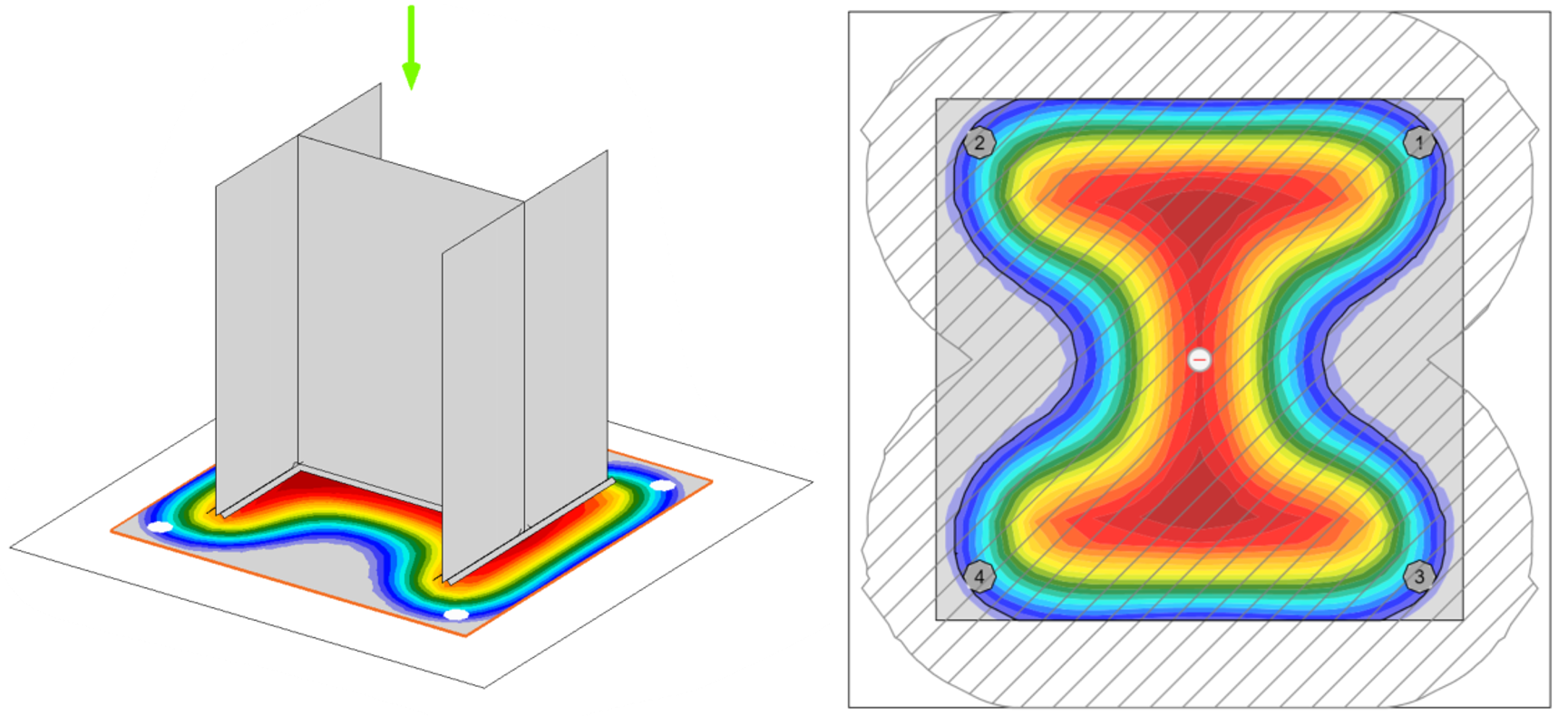
Vedere tridimensională (stânga) și vedere în plan (dreapta) a tensiunii în beton la interfața oțel-beton a unei îmbinări cu placă de bază încărcată concentric. Limita ariei de reazem (A1 în Secțiunea J8 a Specificației AISC) este prezentată ca o linie neagră continuă în vederea în plan. Se remarcă forma neregulată care urmează contururile de tensiune și găurile pentru ancorele de fundație. Suprafața de suport din beton (A2 în Secțiunea J8 a Specificației AISC) este prezentată ca regiunea hașurată a vederii în plan și este, de asemenea, neregulată.
Informații suplimentare pot fi găsite în aceste articole:
- https://www.ideastatica.com/support-center/general-theoretical-background#Structural_model_of_a_concrete_block
- https://www.ideastatica.com/support-center/check-of-components-according-to-aisc
- https://www.ideastatica.com/support-center/check-of-concrete-blocks-according-to-aisc
- https://www.ideastatica.com/support-center/base-plate-connections-aisc
Încovoierea Locală a Tălpii
Încovoierea locală a tălpii este una dintre stările limită care se aplică forțelor concentrate aplicate normal pe talpa profilelor cu tălpi late și a formelor similare sudate. Se aplică doar forțelor concentrate de întindere. Rezistența nominală pentru starea limită de încovoiere locală a tălpii este definită în Secțiunea J10.1 a Specificației AISC (2022).
Așa cum este descris în comentariul la Secțiunea J10.1, starea limită de încovoiere locală a tălpii a fost inițial destinată să prevină fractura sudurii, care putea apărea prematur din cauza solicitărilor neuniforme datorate deformației tălpii. Cu toate acestea, teste mai recente au arătat că fractura sudurii nu apare când rezistența la încovoiere locală a tălpii este depășită, ci că rezistența la încovoiere locală a tălpii reprezintă o limită inferioară la care deformația tălpii ar putea duce la flambaj local prematur al tălpii sau ar putea fi dăunătoare altor aspecte ale performanței elementului. Comentariul menționează în continuare că, deși deformațiile tălpii pot apărea și sub forțe de compresiune, Specificația AISC nu impune verificarea încovoierii locale a tălpii pentru forțe de compresiune, deoarece este obișnuit să se efectueze verificarea doar pentru forțe de întindere.
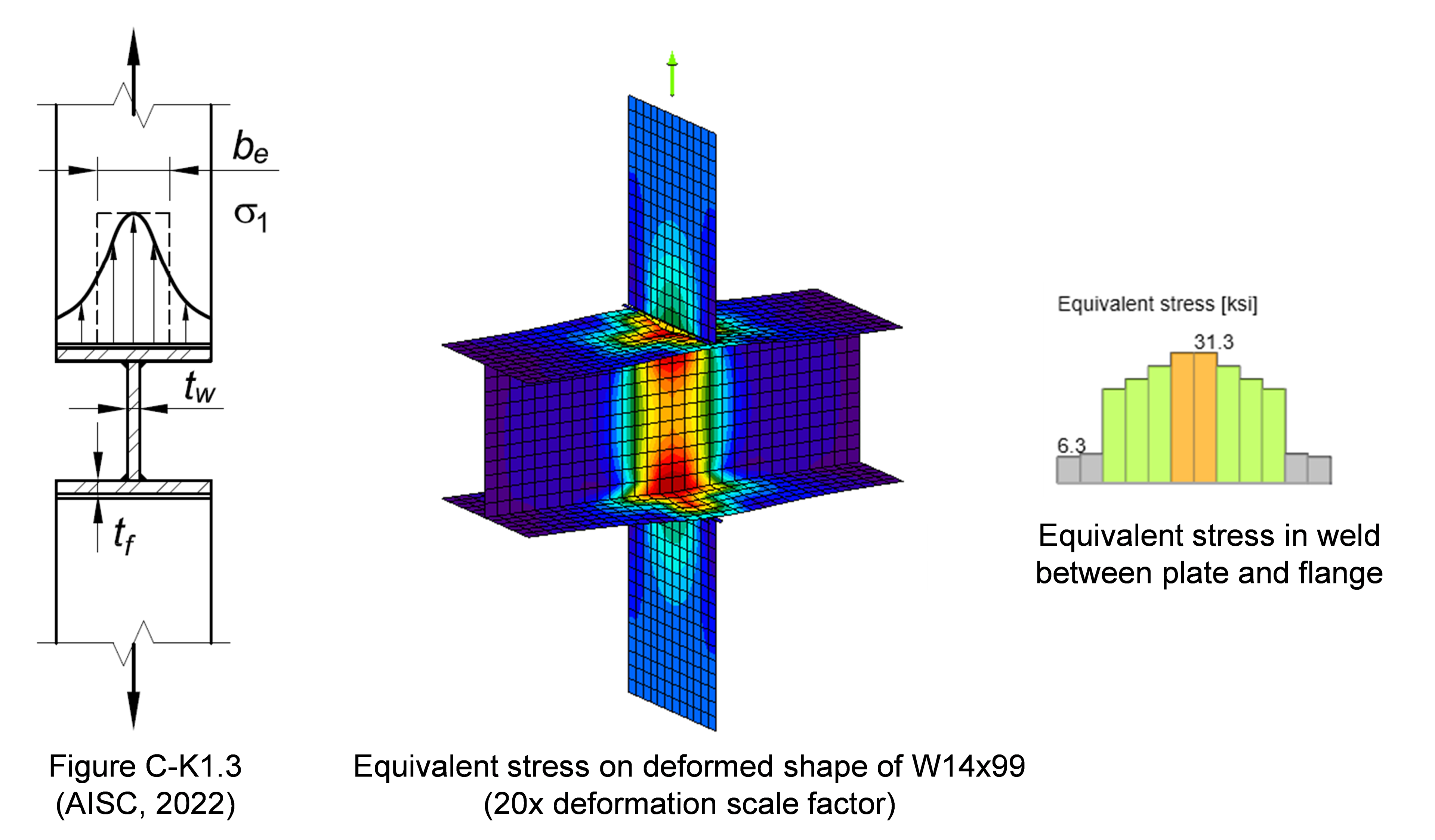
Așa cum se arată în figura de mai sus, atât distribuția neuniformă a tensiunilor, cât și deformațiile tălpii sunt modelate explicit în IDEA StatiCa. Fiecare segment de sudură este verificat independent pentru rezistență. Cazuri precum cel prezentat în figura de mai sus au fost examinate în calibrarea și ulterior validarea și verificarea modelului de sudură în IDEA StatiCa. Cu toate acestea, pentru profile altele decât HSS, deformațiile locale ale tălpii nu sunt verificate față de o limită, efectul lor asupra performanței elementului nu este evaluat, iar magnitudinea lor nu poate fi obținută direct din model. Ca urmare, starea limită de încovoiere locală a tălpii nu este evaluată în IDEA StatiCa. Acolo unde încovoierea locală a tălpii controlează calculele tradiționale, rezistențe semnificativ mai mari pot fi obținute din IDEA StatiCa. Acolo unde deformațiile tălpii reprezintă o preocupare, se recomandă evaluarea stării limită în afara IDEA StatiCa.
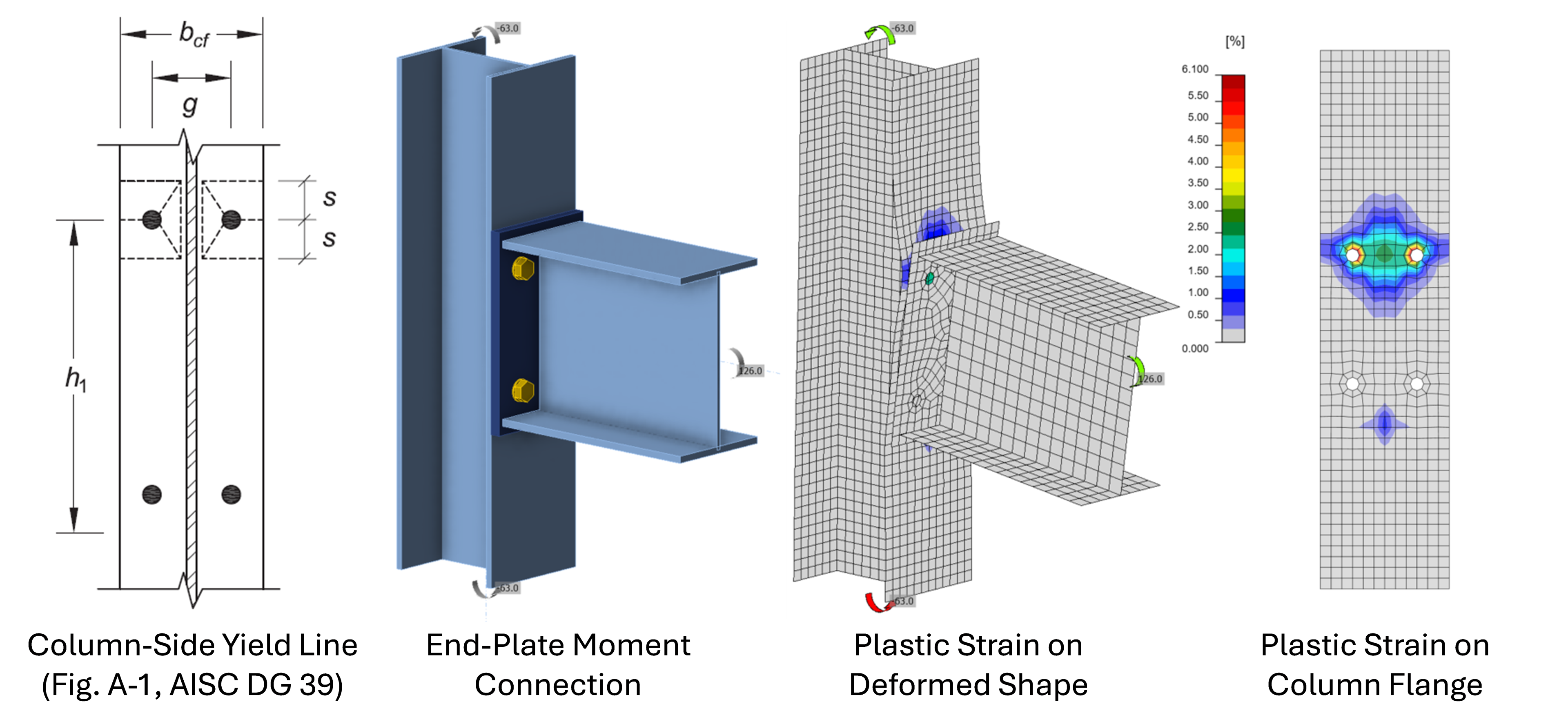
De remarcat că curgerea la încovoiere a tălpilor în îmbinările cu șuruburi este considerată o stare limită separată. În calculele tradiționale, rezistența disponibilă este determinată de obicei folosind teoria liniilor de curgere, după cum este descris de Dowswell (2011) pentru îmbinări generale sau Eatherton și Murray (2023) pentru îmbinările cu moment și placă de capăt. IDEA StatiCa captează această stare limită prin modelarea explicită a tălpii, după cum se arată în figura de mai jos.
Curgerea Locală a Inimii
Curgerea locală a inimii este una dintre stările limită care se aplică forțelor concentrate aplicate normal pe talpa profilelor cu tălpi late și a formelor similare sudate. Ecuațiile de rezistență nominală pentru curgerea locală a inimii din Secțiunea J10.2 a Specificației AISC se bazează pe curgerea inimii pe o lungime egală cu lungimea de reazem plus o distribuție presupusă a forței prin talpă. Deși curgerea inimii este modelată explicit în IDEA StatiCa, mai multe caracteristici ale ecuațiilor de proiectare nu sunt. Ecuațiile presupun un gradient de tensiune de 2,5:1 prin talpă și racordarea profilelor laminate. În IDEA StatiCa, talpa este modelată cu elemente de tip placă, iar racordarea este neglijată, astfel că distribuția forțelor depinde în mare măsură de constrângerile dintre talpă și inimă. Există două ecuații separate în Secțiunea J10.2 a Specificației AISC pentru curgerea locală a inimii, în funcție de distanța forței față de capetele elementului. În IDEA StatiCa, reducerea rezistenței datorată proximității față de capătul elementului este captată prin modelarea directă a elementului. Un factor de rezistență de ϕ = 1,00 și un factor de siguranță de Ω = 1,50 se aplică stării limită de curgere locală a inimii. IDEA StatiCa nu utilizează acești factori și în schimb reduce punctul de curgere cu un factor de 0,9 pentru LRFD sau prin împărțire la 1,67 pentru ASD, pe baza factorului tipic de rezistență și a factorului de siguranță pentru curgere.
Efectul global al acestor diferențe a fost investigat pentru îmbinările grindă-peste-stâlp în acest articol și pentru forțe concentrate generice în acest raport.
Flambajul la Compresiune al Inimii
Flambajul la compresiune al inimii este una dintre stările limită care se aplică forțelor concentrate aplicate normal pe talpa profilelor cu tălpi late și a formelor similare sudate. Se aplică când o pereche de forțe comprimă inima de la ambele tălpi în același punct de-a lungul lungimii elementului. Secțiunea J10.5 a Specificației AISC furnizează o ecuație pentru rezistența nominală la flambaj la compresiune al inimii. Ecuația se bazează pe rezistența elastică la flambaj a unei plăci simplu rezemate supuse la forțe concentrate egale și opuse.
În IDEA StatiCa, proiectarea pentru flambajul la compresiune al inimii poate fi realizată prin asigurarea că sarcina critică elastică de flambaj este suficient de mare (a se vedea discuția din intrarea privind Curgerea la Compresiune și Flambaj). Prin comparații cu analiza geometrică și materială neliniară cu imperfecțiuni incluse (GMNIA), un raport al sarcinii critice elastice de flambaj de 3 a fost determinat ca o limită inferioară adecvată.
Curgerea la Forfecare a Zonei de Nod a Inimii
Rezistența disponibilă pentru starea limită de curgere la forfecare a zonei de nod a profilelor cu tălpi late și a formelor similare sudate este definită în Secțiunea J10.6 a Specificației AISC. Patru ecuații diferite sunt furnizate în această secțiune pentru rezistența nominală. O pereche de ecuații este furnizată pentru cazul în care efectul deformației inelastice a zonei de nod asupra stabilității cadrului nu este luat în considerare în analiză, iar o altă pereche pentru cazul în care este luat în considerare. Prima pereche de ecuații limitează comportamentul zonei de nod la domeniul elastic. A doua pereche de ecuații furnizează o rezistență mai mare; cu toate acestea, deformația plastică a zonei de nod este necesară pentru a atinge o rezistență mai mare. Deformațiile suplimentare pot crește semnificativ deformațiile globale ale cadrului și efectele de ordinul doi. Dacă potențialul de deformație inelastică a zonei de nod nu este luat în considerare în calculul rezistențelor solicitate ale elementelor și îmbinărilor, atunci Secțiunea J10.6 a Specificației AISC impune limitarea comportamentului zonei de nod la domeniul elastic.
În IDEA StatiCa, curgerea la forfecare a zonei de nod este modelată explicit cu elemente de tip placă neliniare și este limitată de o limită de deformație plastică. Starea limită de curgere la forfecare a zonei de nod a fost explorată pentru îmbinările cu moment și placă de capăt extinsă în acest articol și pentru îmbinările cu moment și placă de talpă cu șuruburi în acest articol. Utilizând limita implicită de deformație plastică de 5%, rezistența din IDEA StatiCa depășește cea din Specificația AISC pentru cazul în care efectul deformației inelastice a zonei de nod asupra stabilității cadrului nu este luat în considerare în analiză. Cu toate acestea, reducerea limitei de deformație plastică la o valoare mică (de ex., 0,1%) în IDEA StatiCa impune un comportament esențial elastic și rezultă în rezistențe precise în comparație cu ecuațiile Specificației AISC pentru cazul în care efectul deformației inelastice a zonei de nod asupra stabilității cadrului nu este luat în considerare în analiză.
Inginerii trebuie să știe dacă efectul deformației inelastice a zonei de nod asupra stabilității cadrului a fost luat în considerare în analiza pentru determinarea rezistențelor solicitate (adică, nu analiza IDEA StatiCa). Și, dacă nu a fost, aceștia trebuie să limiteze comportamentul zonei de nod la un comportament esențial elastic.
Îmbinări la Elemente HSS
Capitolul K al Specificației AISC (2022) include cerințe suplimentare, față de cele din Capitolul J, care se aplică îmbinărilor la elemente HSS și secțiuni tip cutie care se comportă ca elemente HSS. Capitolul K este organizat pe tipuri de îmbinări, iar cerințele sunt adesea însoțite de limite de aplicabilitate. Cu toate acestea, Capitolul K nu interzice utilizarea îmbinărilor cu alte configurații sau a celor în afara limitelor de aplicabilitate.
Stările limită descrise în tabelele Capitolului K sunt evaluate în IDEA StatiCa prin modelare explicită și limita de deformație plastică de 5%. Efectele parametrilor definiți în Secțiunea K1, inclusiv lățimea efectivă pentru îmbinările la HSS rectangular pentru a ține cont de distribuțiile neuniforme ale tensiunilor, parametrul de interacțiune a tensiunii în corzi și distanța față de capăt, sunt, de asemenea, modelate explicit. Pentru a crește precizia, neliniaritatea geometrică este inclusă în model implicit când o secțiune transversală tubulară este utilizată ca element de reazem.
Comentariul la Capitolul K precizează: „Când se utilizează analiza neliniară cu elemente finite, deformațiile de vârf în elementele de tip placă groasă (T × T × T) nu trebuie să depășească 0,02/T la capacitatea nominală, unde T este grosimea în inch." Neglijând diferența dintre deformație și deformație plastică, valoarea limită a acestei recomandări este mai mare decât 5% utilizat de IDEA StatiCa când grosimea este mai mică de 0,4 in. Deși limita de deformație din recomandarea comentariului este mai restrictivă decât limita implicită din IDEA StatiCa pentru tuburi mai groase, limita de deformație plastică de 5% este mai larg recunoscută ca o limită acceptabilă pentru proiectarea la rezistență, inclusiv de către Steel Tube Institute.
Capitolul K se bazează exclusiv pe stări limită de rezistență. Ca urmare, deformații mari pot apărea în îmbinările care îndeplinesc cerințele Capitolului K. Cu toate acestea, deformația locală în afara planului a elementelor HSS este verificată în IDEA StatiCa față de o limită de 3% din cea mai mică dimensiune transversală a secțiunii transversale (adică, diametrul sau lățimea), pe baza cerințelor altor standarde.
Deoarece prevederile Capitolului K se bazează în mare parte pe cercetări internaționale și pe activitatea comitetelor internaționale, verificările față de alte standarde sunt în general informative pentru practica din SUA. Mai multe studii de verificare pentru îmbinările la elemente HSS sunt disponibile pe site-ul IDEA StatiCa, inclusiv pentru îmbinările între secțiuni tubulare rectangulare, secțiuni tubulare circulare, plăci și secțiuni tubulare rectangulare și plăci și secțiuni tubulare circulare.
Considerații și Cerințe de Proiectare
Baza de Proiectare
Proiectarea pentru rezistență conform Specificației AISC se realizează fie cu prevederile pentru proiectarea pe baza factorilor de încărcare și rezistență (LRFD), fie cu prevederile pentru proiectarea pe baza rezistenței admisibile (ASD). Deși aceste două abordări au rezistențe solicitate diferite și rezistențe disponibile diferite, rezistențele nominale sunt aceleași, iar proiectele finale ar trebui să fie similare, dacă nu identice.
| Criteriu de rezistență | Rezistență solicitată | Rezistență disponibilă | Rezistență nominală | |
| LRFD | \(R_u \le \phi R_n\) | Ru calculat folosind combinațiile de încărcare LRFD (ex., 1.2D + 1.6L + 0.5Lr) | \(\phi\)Rn denumit și rezistența de calcul (\(\phi\) este un factor de rezistență) | Rn |
| ASD | \(R_a \le R_n/\Omega\) | Ra calculat folosind combinațiile de încărcare ASD (ex., D + L) | Rn/Ω denumit și rezistența admisibilă (Ω este un factor de siguranță) | Rn |
Rezistențele solicitate sunt mai mari pentru LRFD decât pentru ASD, datorită factorilor de încărcare mai mari din combinațiile de încărcare LRFD. Diferențele în rezistențele solicitate pot apărea și atunci când acestea sunt calculate prin analiză neliniară, iar nivelul de neliniaritate depinde de nivelul de încărcare. Pentru a compensa acest lucru în proiectarea pentru stabilitate, Specificația AISC impune ca toate efectele dependente de încărcare să fie calculate la un nivel de încărcare corespunzător combinațiilor de încărcare LRFD sau de 1,6 ori combinațiile de încărcare ASD. IDEA StatiCa urmează o abordare diferită. În IDEA StatiCa, limita de curgere pentru elementele de tip placă este considerată 0,9Fy pentru LRFD și Fy/1,67 pentru ASD, valorile 0,9 și 1,67 corespunzând factorului de rezistență și, respectiv, factorului de siguranță tipici pentru stările limită de curgere. În majoritatea cazurilor, aceasta conduce la încărcări aplicate maxime admise de 1,5 ori mai mari pentru LRFD decât pentru ASD, în concordanță cu prevederile Specificației AISC. Cu toate acestea, modulul de elasticitate nu este redus în IDEA StatiCa nici pentru LRFD, nici pentru ASD. Prin urmare, raportul dintre rigiditate și rezistență diferă între cele două abordări, generând anumite consecințe în proiectare. Pentru flambaj, raportul limită al încărcării elastice critice diferă între LRFD și ASD. De asemenea, acolo unde rigiditatea unei îmbinări influențează rezistența acesteia, de ex., îmbinări sudate lungi, raportul încărcărilor aplicate maxime admise între LRFD și ASD poate devia de la 1,5. Majoritatea studiilor de validare care compară IDEA StatiCa cu Specificația AISC au fost efectuate pentru LRFD.
IDEA StatiCa implementează prevederile pentru ASD definite în Specificația AISC 2022. Prevederile din Specificația AISC 2022 pentru ASD diferă de cele din standardele istorice, cum ar fi Specificația AISC din 1989, inclusă în ediția a 9a a Manualului AISC (denumit în mod curent „cartea verde"). Prevederile istorice pentru ASD se concentrau pe comportamentul elastic și prezentau mai multe diferențe față de LRFD. Prevederile actuale pentru ASD sunt mai consistente cu LRFD, incluzând calcule comune ale rezistenței nominale.
Materiale din oțel structural
Secțiunea A3.1 din Specificația AISC include cerințe pentru materialele din oțel structural. În această secțiune, Tabelul A3.1 listează materiale specifice care au un istoric de performanță satisfăcătoare și sunt considerate a se comporta conform prevederilor Specificației AISC. Materialele listate includ profile laminate cu limita de curgere de până la 80 ksi și table cu limita de curgere de până la 100 ksi. Materialele care nu sunt listate în Tabelul A3.1 sunt permise atunci când utilizarea lor este considerată acceptabilă de către inginerul responsabil. Mulți factori pot influența adecvarea materialelor, inclusiv utilizarea prevăzută, proprietățile de rezistență în direcții transversale, ductilitatea și sudabilitatea.
Având în vedere verificarea extinsă a IDEA StatiCa față de prevederile Specificației AISC, materialele listate în Tabelul A3.1 pot fi considerate, de asemenea, ca performând conform așteptărilor în software. Utilizarea materialelor care nu sunt listate în Tabelul A3.1 nu este interzisă, dar rămâne la latitudinea inginerului responsabil. Comentariul la Secțiunea A3.1 din Specificația AISC include o discuție despre factorii care influențează adecvarea materialelor și îndrumări pentru evaluarea acesteia.
Efectul de pârghie
În îmbinările cu șuruburi, contactul dintre elementele de îmbinare poate crește forțele de întindere peste cele datorate numai încărcărilor aplicate. Acest fenomen este cunoscut sub numele de efectul de pârghie și apare doar în îmbinările cu forțe de întindere în șuruburi. Contactul care mărește forțele din șuruburi apare din cauza deformării elementului de îmbinare. Prin urmare, efectul de pârghie reprezintă o considerație de proiectare atât pentru șuruburi, cât și pentru elementele de îmbinare.
Rigiditatea și rezistența relative ale șuruburilor și ale elementelor de îmbinare controlează comportamentul. Dacă elementele de îmbinare sunt rigide în raport cu șuruburile, atunci elementele de îmbinare se vor deforma fără a se încovoaia înapoi și a face contact, iar efectul de pârghie nu va apărea. În acest caz, rezistența șuruburilor va controla proiectarea. Dacă elementele de îmbinare sunt slabe în raport cu șuruburile, atunci elementele de îmbinare vor ceda și vor transmite forțe de pârghie asupra șuruburilor, limitând totodată forța din șuruburi. În acest caz, rezistența elementelor de îmbinare va controla proiectarea. Între aceste extreme, rezistența șuruburilor și a elementelor de îmbinare controlează simultan proiectarea.
Îndrumări pentru luarea în considerare a efectului de pârghie în proiectare sunt furnizate în Partea 9 a AISC Manual. Ecuațiile prezentate în AISC Manual au fost dezvoltate pentru cazurile comune ale unui profil T și al unor corniere spate-în-spate și validate pe baza datelor experimentale. IDEA StatiCa modelează explicit rigiditatea și rezistența șuruburilor și a elementelor de îmbinare, inclusiv contactul, astfel încât efectul de pârghie este surprins în mod natural de analiză, indiferent de configurația specifică. O comparație între ecuațiile din AISC Manual și rezultatele IDEA StatiCa a fost realizată pentru îmbinări de tip T-stub. O comparație similară cu abordarea de proiectare pentru efectul de pârghie recomandată în Guide to Design Criteria for Bolted and Riveted Joints (Kulak et al. 1987) a fost de asemenea realizată. Efectul de pârghie este prezentat în alte exemple de verificare, inclusiv pentru îmbinări de contravântuire și îmbinări cu placă de capăt extinsă cu moment încovoietor.
Compatibilitatea Deformațiilor în Îmbinările Lungi
În îmbinările lungi cu încărcare la capete, diferența de alungire dintre elementele conectate este maximă la capetele îmbinării. Ca urmare, tensiunea în șuruburi și suduri în îmbinările lungi cu încărcare la capete nu este uniformă. Deoarece în calculele tradiționale se presupune în mod obișnuit o distribuție uniformă a tensiunilor, Specificația AISC include reduceri ale lungimii sudurilor lungi cu încărcare la capete și ale tensiunii nominale de forfecare a șuruburilor. Secțiunea J2.2b din Specificația AISC definește lungimea efectivă a sudurilor de colț cu încărcare la capete, inclusiv reducerile aplicabile atunci când lungimea sudurii depășește de 100 de ori dimensiunea sudurii. Valorile tensiunii nominale de forfecare din Tabelul J3.2 al Specificației AISC includ o reducere de 10% pentru a ține cont de efectele lungimii, iar o reducere suplimentară este necesară pentru îmbinările cu încărcare la capete cu o lungime a grupului de dispozitive de fixare mai mare de 38 in.
IDEA StatiCa nu aplică aceste reduceri în mod direct. În schimb, comportamentul de bază care motivează aceste reduceri este modelat explicit. IDEA StatiCa modelează rigiditatea șuruburilor, sudurilor și elementelor de îmbinare, astfel încât distribuția neuniformă a tensiunilor în șuruburi și suduri apare în mod natural. Prin evaluarea individuală a rezistenței șuruburilor și a segmentelor de sudură, rezistența rezultată a îmbinării este comparabilă cu cea obținută din calculele tradiționale. O comparație detaliată între IDEA StatiCa și rezultatele obținute prin calcule tradiționale pentru îmbinările lungi cu încărcare la capete este prezentată în acest articol.
Compatibilitatea Deformațiilor în Grupuri de Șuruburi și Suduri Solicitate Excentric
Șuruburile și sudurile din grupuri solicitate excentric sunt supuse forfecării directe plus forfecării suplimentare din momentul indus. Tensiunea rezultantă în șuruburi sau suduri variază atât ca mărime, cât și ca direcție de la șurub la șurub și de la un segment de sudură la altul. Așa cum este descris în Părțile 7 și 8 ale Manualului AISC, inginerii pot utiliza metoda centrului instantaneu de rotație sau metoda elastică pentru a analiza grupuri de șuruburi sau suduri solicitate excentric. Calculele folosind metoda centrului instantaneu de rotație sunt efectuate de obicei cu ajutorul valorilor tabulate furnizate în Manualul AISC.
În IDEA StatiCa, rezistența necesară a șuruburilor și segmentelor de sudură este determinată din rezultatele analizei neliniare. Fiecare șurub și segment de sudură este modelat individual și echilibrul este impus. Rezistențele disponibile sunt determinate conform Specificației AISC.
Metoda centrului instantaneu de rotație se bazează, de asemenea, pe analiza neliniară, dar există diferențe esențiale între analizele neliniare ale metodei centrului instantaneu de rotație și IDEA StatiCa. În metoda centrului instantaneu de rotație, elementele de îmbinare sunt considerate rigide, ceea ce nu este cazul în IDEA StatiCa. Răspunsul forță-deformație al șuruburilor și sudurilor diferă, de asemenea, între cele două metode. Răspunsul forță-deformație utilizat în IDEA StatiCa pentru șuruburi și suduri este biliniar și este descris în baza teoretică.
Diferențele conduc în general la rezistențe similare sau mai mici din IDEA StatiCa, așa cum se arată în acest articol despre îmbinările cu placă de consolă. Comparații între calculele tradiționale și IDEA StatiCa pentru grupuri de șuruburi solicitate excentric sunt realizate și în acest articol despre îmbinările cu placă unică la forfecare.
Șuruburi în Combinație cu Suduri
Predicția precisă a rezistenței este mai dificilă când șuruburile și sudurile împart sarcina pe o suprafață de contact comună. Ductilitatea mai mică a sudurilor în comparație cu șuruburile poate duce la fractura fragilă înainte ca rezistența completă a șurubului să fie realizată. Secțiunea J1.8 a Specificației AISC permite ca șuruburile și sudurile să fie considerate ca împărțind sarcina doar în anumite circumstanțe.
Conform Secțiunii J1.8, șuruburile pot fi considerate ca împărțind sarcina cu sudurile doar în proiectarea îmbinărilor la forfecare pe o suprafață de contact comună, unde compatibilitatea deformațiilor dintre șuruburi și suduri este luată în considerare. Secțiunea descrie, de asemenea, un caz cu șuruburi de înaltă rezistență pretensionate și suduri de colț longitudinale, unde rezistența nominală poate fi determinată ca suma rezistenței nominale la alunecare și a rezistenței nominale a sudurii. Șuruburile și sudurile trebuie să suporte fiecare o proporție specificată din sarcină, iar un factor de rezistență de ϕ = 0,75 sau un factor de siguranță de Ω = 2,00 se aplică îmbinării combinate.
Verificările rezistenței pentru șuruburi și suduri sunt independente în IDEA StatiCa, fără o tratare specială a cazului în care șuruburile și sudurile împart sarcina. Dat fiind modelarea explicită a rigidității șuruburilor, sudurilor, elementelor structurale și elementelor de conectare, compatibilitatea deformațiilor este întotdeauna luată în considerare în IDEA StatiCa. Când șuruburile și sudurile împart sarcina, rezistența solicitată a fiecăruia se bazează pe rigiditatea lor relativă, iar rezistența disponibilă se calculează ca de obicei. Acest lucru este valabil chiar și pentru îmbinările la întindere; prin urmare, se recomandă să nu se modeleze șuruburile și sudurile ca împărțind sarcina pentru îmbinările la întindere și să se bazeze în schimb doar pe unul sau pe celălalt.
Pentru a ilustra diferențele dintre metoda furnizată în Secțiunea J1.8 a Specificației AISC și IDEA StatiCa, se consideră îmbinarea dintre plăci supuse la întindere prezentată mai jos.
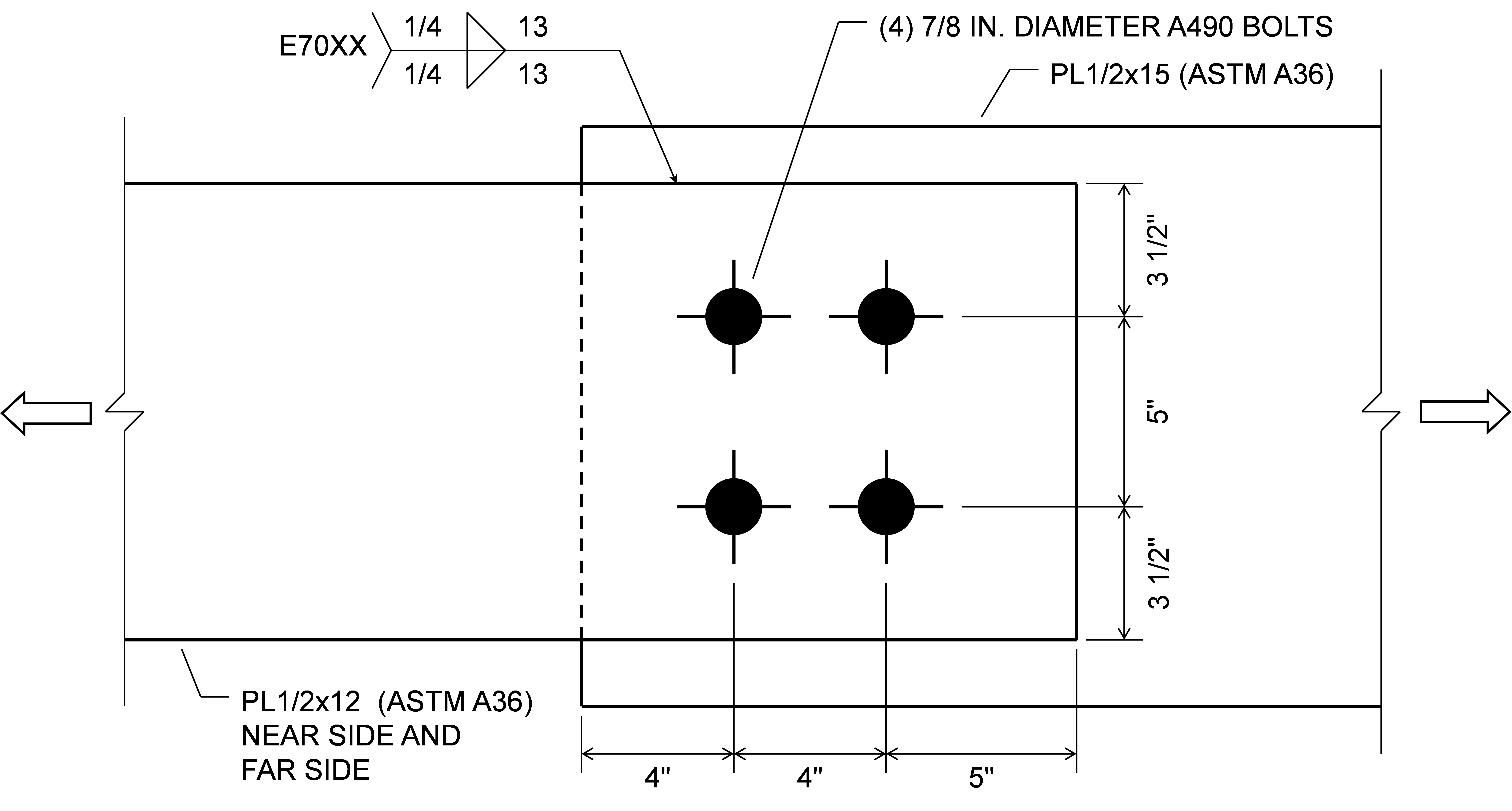
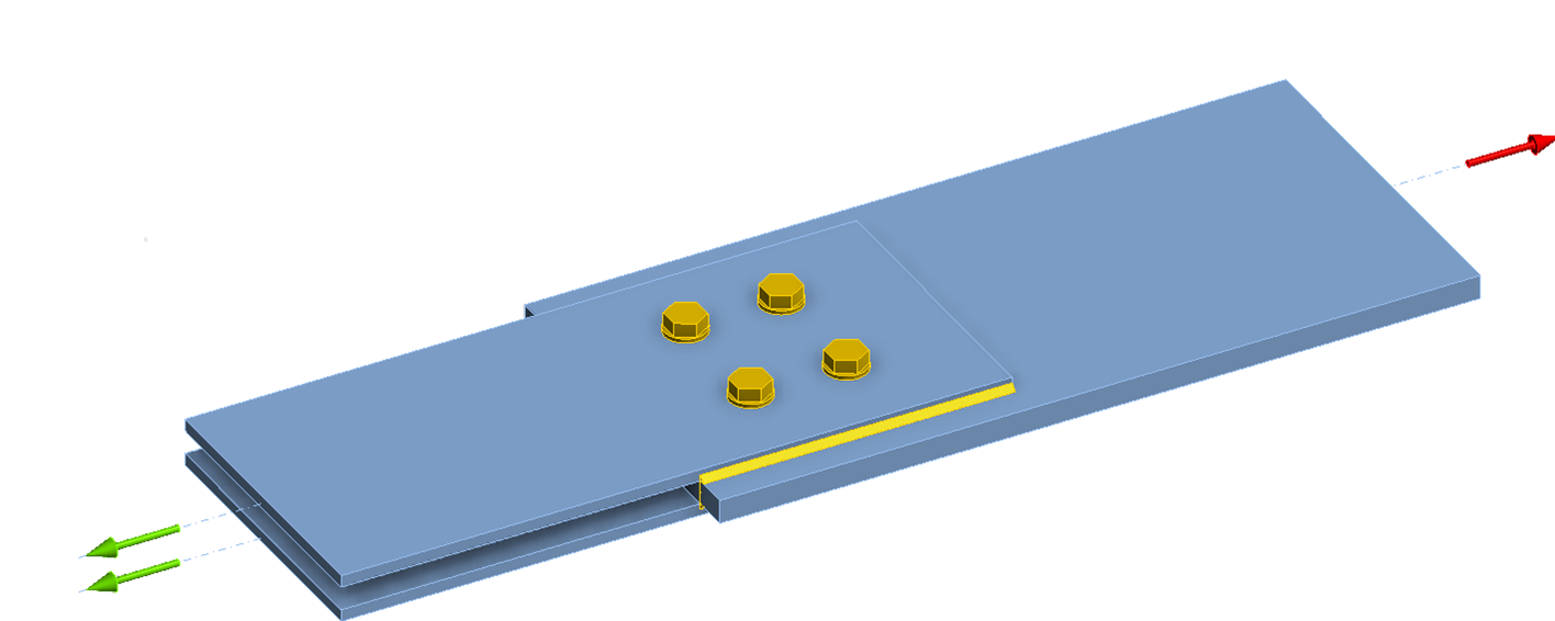
Conform Specificației AISC, când îmbinarea este proiectată ca rezistentă la alunecare, rezistența de calcul a șuruburilor singure este ϕRn = 133 kips (Rn = 133 kips). Rezistența de calcul a sudurilor singure este ϕRn = 290 kips (Rn = 386 kips). Când se combină șuruburile și sudurile, rezistența totală a îmbinării este ϕRn = 0,75 (133 + 386) = 389 kips, deoarece toate cerințele din Secțiunea J1.8 pentru a permite sumarea rezistențelor șuruburilor și sudurilor sunt îndeplinite.
În IDEA StatiCa, întinderea aplicată maximă admisă este de 126 kips când sunt modelate doar șuruburile și de 277 kips când sunt modelate doar sudurile. Diferența dintre rezistența șuruburilor în IDEA StatiCa și rezistența de calcul de 133 kips se datorează faptului că întinderea în șuruburi se dezvoltă în model și este tratată conservativ ca o întindere aplicată în IDEA StatiCa (a se vedea intrarea privind Alunecarea). Diferența dintre rezistența sudurilor în IDEA StatiCa și rezistența de calcul de 277 kips se datorează solicitărilor neuniforme de-a lungul lungimii sudurii în IDEA StatiCa. Când atât șuruburile, cât și sudurile sunt modelate, întinderea aplicată maximă admisă este de 394 kips, cu atât șuruburile, cât și sudurile prezentând un grad de utilizare de 100%. Această valoare este comparabilă cu rezistența de 389 kips din Specificația AISC.
Dacă se presupune că șuruburile sunt de tip presiune de contact, rezistența de calcul pentru șuruburi conform Specificației AISC este ϕRn = 245 kips. Deși Specificația AISC permite ca șuruburile să fie considerate ca împărțind sarcina cu sudurile în îmbinările la forfecare, aceasta nu furnizează o metodă pentru evaluarea rezistenței când șuruburile nu îndeplinesc cerințele unei îmbinări rezistente la alunecare. Prin urmare, ar fi obișnuit să se evalueze rezistența acestei îmbinări ca cea a sudurilor singure sau ϕRn = 290 kips.
În IDEA StatiCa, când șuruburile sunt modelate ca șuruburi de tip presiune de contact și sudurile nu sunt modelate, întinderea aplicată maximă admisă corespunde rezistenței de calcul de 245 kips din Specificația AISC. Când șuruburile sunt modelate ca șuruburi de tip presiune de contact și sudurile sunt modelate, întinderea aplicată maximă admisă este de 311 kips, cu rezistența sudurilor ca limită de control. Această rezistență este cu doar 12% mai mare decât rezistența sudurilor singure conform IDEA StatiCa. Creșterea minoră a rezistenței odată cu adăugarea șuruburilor de tip presiune de contact se datorează faptului că șuruburile sunt mai puțin rigide decât sudurile și, prin urmare, nu atrag multă sarcină înainte ca sudurile să atingă un grad de utilizare de 100%.
Efectul Dimensiunii Găurii
Secțiunea J3.3 din Specificația AISC (2022) descrie utilizarea găurilor standard, supradimensionate, cu fante scurte și cu fante lungi pentru șuruburi în îmbinările din oțel structural. Găurile standard sunt implicite în IDEA StatiCa. Găurile supradimensionate pot fi obținute prin editarea diametrului găurii în ansamblul de șuruburi. Găurile cu fante pot fi definite pentru plăci în editorul de plăci.
Dimensiunea găurii afectează mai multe aspecte ale comportamentului, iar unele cerințe de proiectare se bazează pe dimensiunea găurii.
- Materialul eliminat pentru găurile de șuruburi afectează aria netă. Acest efect este abordat explicit în IDEA StatiCa prin definirea modelului de elemente de tip placă pentru elemente și elemente de îmbinare. Cu toate acestea, cei 1/16 in. suplimentari pentru deteriorare, impuși de Secțiunea B4.3b din Specificația AISC, nu sunt implementați automat (a se vedea Determinarea Ariei Nete)
- Dimensiunea găurii afectează distanța liberă utilizată pentru determinarea rezistenței la sfâșiere. Acest efect este abordat explicit în IDEA StatiCa prin calculul distanței libere pe baza geometriei materialului îmbinat și a direcției forței în șurubul individual.
- Găurile supradimensionate nu sunt permise în îmbinările de tip rezemare. IDEA StatiCa nu verifică această cerință și va permite utilizarea transferului de forță de forfecare prin rezemare cu găuri supradimensionate.
- Factorul de rezistență pentru starea limită de alunecare depinde de tipul găurii. IDEA StatiCa nu ajustează automat factorul de rezistență în funcție de tipul găurii. Factorul de rezistență poate fi setat manual în Configurarea codului.
Dimensiunea găurii poate afecta răspunsul forță-deformație al șurubului. Modelul forță-deformație al șurubului utilizat în IDEA StatiCa nu depinde de dimensiunea găurii, însă transferul de forfecare este considerat nul în direcția longitudinală a găurilor cu fante.
Toleranță de laminare
Variația în lungimea elementului poate duce la diferențe semnificative față de dimensiunile utilizate în proiectarea îmbinării. În mai multe calcule din Exemplele de Proiectare AISC, o toleranță de 1/4 in. este scăzută dintr-o lungime pentru a ține cont de posibila toleranță de laminare. IDEA StatiCa nu ia în considerare automat posibila toleranță de laminare, dar aceasta poate fi considerată prin definirea manuală a îmbinării cu toleranța de laminare asumată.
Contact și frecare
Oțelul nu poate trece fizic prin oțel, totuși acesta este comportamentul implicit în analizele cu elemente finite. Suprafețele de contact trebuie definite pentru a preveni suprapunerea materialului în urma deformării. Contactul suprafață-la-suprafață este definit automat prin operațiunile cu grupuri de șuruburi. Contactul suprafață-la-suprafață poate fi definit cu operațiunea „Grup de șuruburi/contact". Contactul muchie-la-muchie sau muchie-la-suprafață poate fi definit cu operațiunea „Sudură generală sau contact".
Nu toate suprafețele de contact potențiale sunt definite automat de IDEA StatiCa. Prin urmare, este important ca utilizatorul să înțeleagă bine comportamentul intenționat al îmbinării și să examineze forma deformată pentru a confirma că îmbinarea este modelată și se comportă conform intenției.
Rezemarea prin contact poate fi un mijloc eficient de transfer al forțelor într-o îmbinare, dacă aceasta a fost detaliată corespunzător și suprafețele sunt pregătite cu grijă astfel încât rezemarea să existe (Muir 2015). Deoarece o detaliere specială este necesară pentru a asigura eficiența rezemării prin contact, contactul muchie-la-muchie și muchie-la-suprafață nu este definit automat în IDEA StatiCa, dar poate fi definit manual folosind operațiunea „Sudură generală sau contact". Înnădirile de stâlpi cu șuruburi reprezintă un exemplu în care definirea contactului muchie-la-muchie între elemente va reduce solicitările din șuruburi, rezultând o îmbinare mai eficientă. Utilizarea rezemării prin contact poate fi, de asemenea, eficientă în combinație cu sudurile dintre stâlpi și plăcile de bază. Sudurile, în mod implicit, nu sunt definite cu contact și, prin urmare, sunt verificate și la forțe de compresiune. Combinarea operațiunilor de sudură și contact poate permite utilizarea unor suduri mai mici. Sudurile sunt rigide și vor atrage încărcarea chiar și atunci când sunt combinate cu contactul, dar solicitările din forțele de compresiune vor depăși rareori capacitatea, chiar dacă dimensiunea sudurii este redusă.
Frecarea la suprafețele de contact oțel-pe-oțel este neglijată în mod conservativ în IDEA StatiCa, cu excepția șuruburilor desemnate să transfere forțe de forfecare prin frecare (adică, șuruburi cu alunecare controlată). Luarea în considerare a frecării doar atunci când șuruburile pretensionate asigură forța de strângere este tipică și pentru calculele tradiționale. Cu toate acestea, unele diferențe în rezultate între IDEA StatiCa și calculele tradiționale pot apărea din cauza frecării. De exemplu, Secțiunea J3.10 din Specificația AISC definește un factor de reducere care se aplică rezistenței la alunecare atunci când o îmbinare cu alunecare controlată este supusă la întindere și forfecare combinate. Factorul de reducere se bazează pe încărcarea de întindere aplicată îmbinării. IDEA StatiCa nu are posibilitatea de a cuantifica cât din forța de întindere dintr-un șurub se datorează încărcării aplicate față de alte surse, cum ar fi efectul de pârghie. Dacă efectul de pârghie induce întindere într-un șurub cu alunecare controlată, atunci rezistența la alunecare va fi redusă în IDEA StatiCa. Rezistența la alunecare conform calculelor tradiționale nu ar fi redusă. O investigație detaliată a acestei diferențe este descrisă pentru îmbinările de tip T-stub în acest articol.
Determinarea Ariei Nete
Secțiunea B4.3b din Specificația AISC (2022) prevede că lățimea unui orificiu pentru șurub trebuie considerată cu 1/16 in. mai mare decât dimensiunea nominală a orificiului la calculul ariei nete în întindere sau forfecare. Aplicarea acestei cerințe reduce aria netă pentru a ține cont de posibilele deteriorări din jurul orificiului în timpul operațiunilor de găurire sau perforare. Această cerință afectează stările limită precum ruperea prin întindere a secțiunii nete și ruperea prin forfecare în bloc, dar nu afectează starea limită de sfâșiere la orificiile pentru șuruburi.
În IDEA StatiCa, ansamblurile de șuruburi implicite au un diametru al orificiului egal cu dimensiunea nominală a orificiului. Prin urmare, deși cei 1/16 in. pot fi adăugați manual la diametrul orificiului prin editarea ansamblului de șuruburi, această cerință nu este abordată automat în IDEA StatiCa. Dacă diametrul orificiului ansamblului de șuruburi este mărit, diametrul mărit se va aplica pentru toate aspectele analizei, inclusiv evaluarea sfâșierii. Discuții suplimentare despre modul în care dimensiunea orificiului afectează rezultatele în IDEA StatiCa pot fi găsite în secțiunea privind Efectul Dimensiunii Orificiului.
Secțiunea B4.3b din Specificația AISC (2022) include, de asemenea, prevederi pentru determinarea ariei nete atunci când un șir de orificii pentru șuruburi se extinde pe un element în orice linie diagonală sau în zigzag. Pentru aceste cazuri, lățimea netă a elementului se obține scăzând din lățimea brută suma diametrelor (inclusiv cei 1/16 in. pentru deteriorare) ale tuturor orificiilor din șir și adăugând, pentru fiecare spațiu de pas din șir, cantitatea s2/4g, unde
g = distanța transversală dintre axele rândurilor de dispozitive de fixare (pas transversal)
s = distanța longitudinală dintre axele oricăror două orificii consecutive pentru șuruburi (pas longitudinal)
Lățimea netă rezultată diferă de lungimea suprafeței de cedare (adică linia roșie întreruptă din figura de mai jos) și ține cont de combinația de întindere și forfecare de-a lungul planului înclinat. Deoarece IDEA StatiCa nu calculează explicit aria netă, prevederile privind lățimea netă nu sunt implementate în software. Cu toate acestea, posibilitatea de cedare de-a lungul unei linii diagonale sau în zigzag de șuruburi, inclusiv interacțiunea dintre întindere și forfecare de-a lungul planului înclinat, este surprinsă explicit prin modelarea elementelor îmbinate.
Efectul decalării rândurilor de șuruburi poate fi observat într-o îmbinare simplă cu eclisă. O placă de test este prinsă cu șuruburi între două plăci de reacțiune și încărcată la întindere. Grosimea plăcii de test este de 1/2 in., iar grosimea fiecărei plăci de reacțiune este de 3/8 in. Toate plăcile au lățimea de 6 in. și sunt conforme cu ASTM A572 Gr 50 (Fy = 50 ksi, Fu = 65 ksi). Îmbinarea are (6) șuruburi A325 cu diametrul de 7/8 in. dispuse în două rânduri decalate. Distanța dintre șuruburile dintr-un rând este de 3 in., pasul transversal, g, este de 3 in., iar distanța la margine este de 1,5 in. Mărimea decalajului dintre cele două rânduri de șuruburi este măsurată prin dimensiunea s.
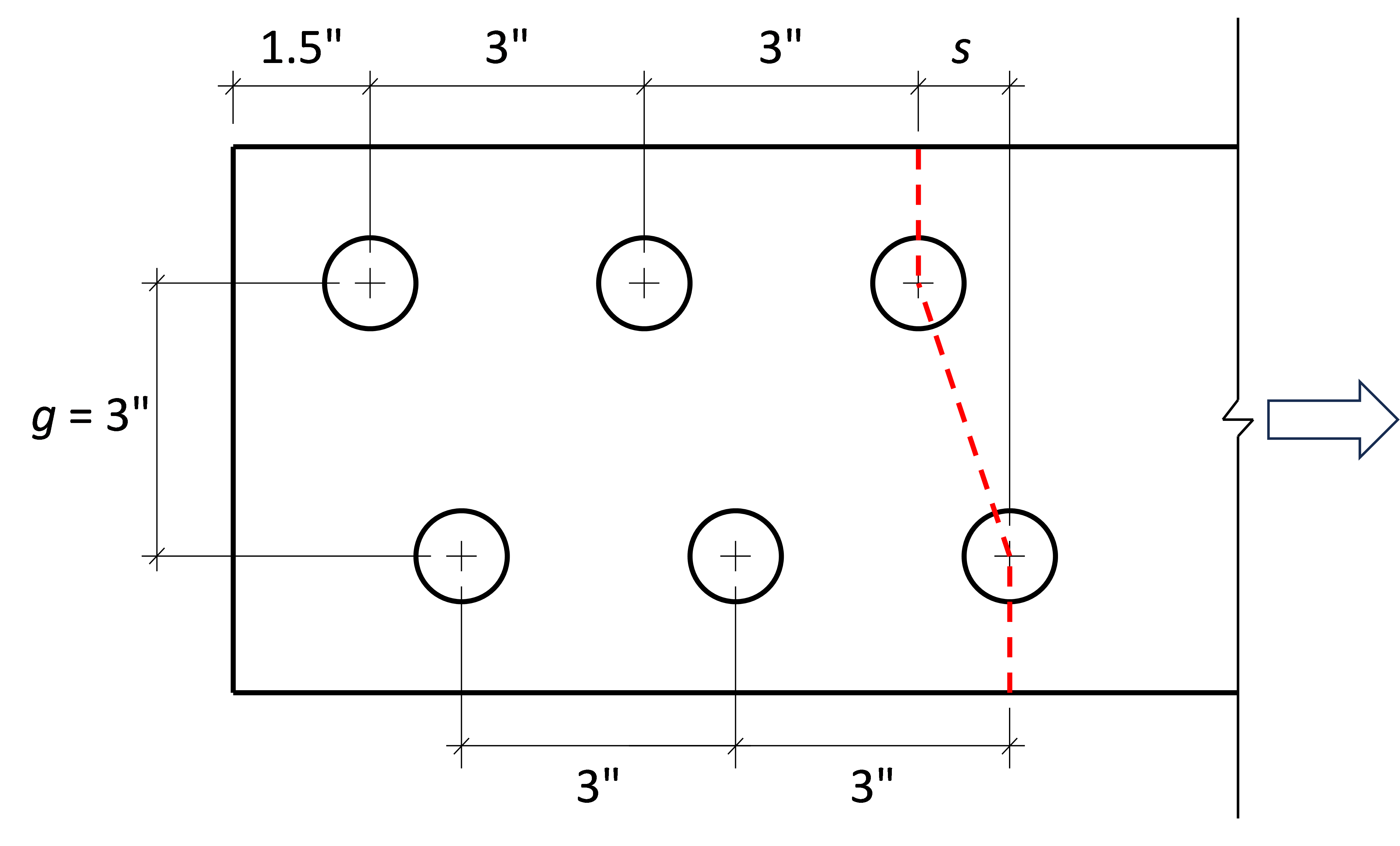
O vedere tridimensională a îmbinării cu s = 1,5 in. este prezentată în figura de mai jos.
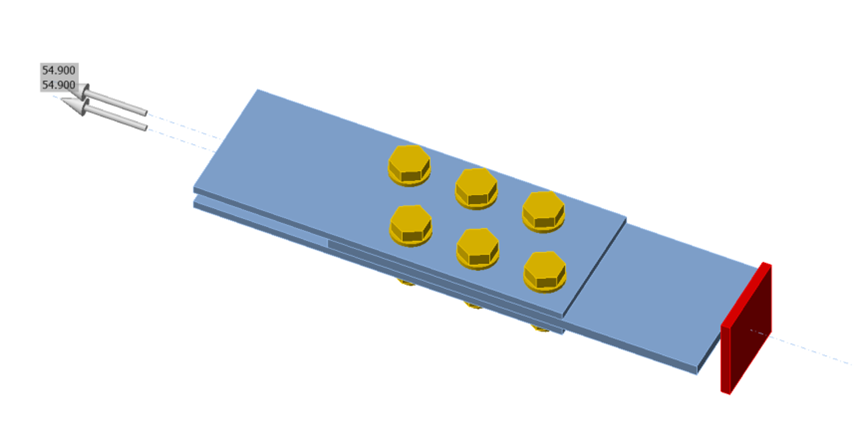
Au fost efectuate analize pentru îmbinări cu dimensiunea s variind de la zero (adică fără decalaj) la 3 in., cu incremente de 0,5 in. Rezistența conform Specificației AISC a fost calculată utilizând prevederile Secțiunii B4.3b. Starea limită de rupere prin întindere de-a lungul liniei în zigzag reprezentată prin linia roșie întreruptă în figura de mai sus a fost determinantă pentru toate cazurile. Rezistența conform IDEA StatiCa a fost determinată iterativ prin analiza efort-deformație, ajustând valoarea încărcării aplicate la o valoare pe care programul o consideră sigură, dar dacă ar fi mărită cu o cantitate mică (0,1 kip), programul ar considera-o nesigură. Limita de 5% a deformației plastice a fost determinantă pentru toate cazurile. Rezultatele analizelor sunt prezentate în figura de mai jos.
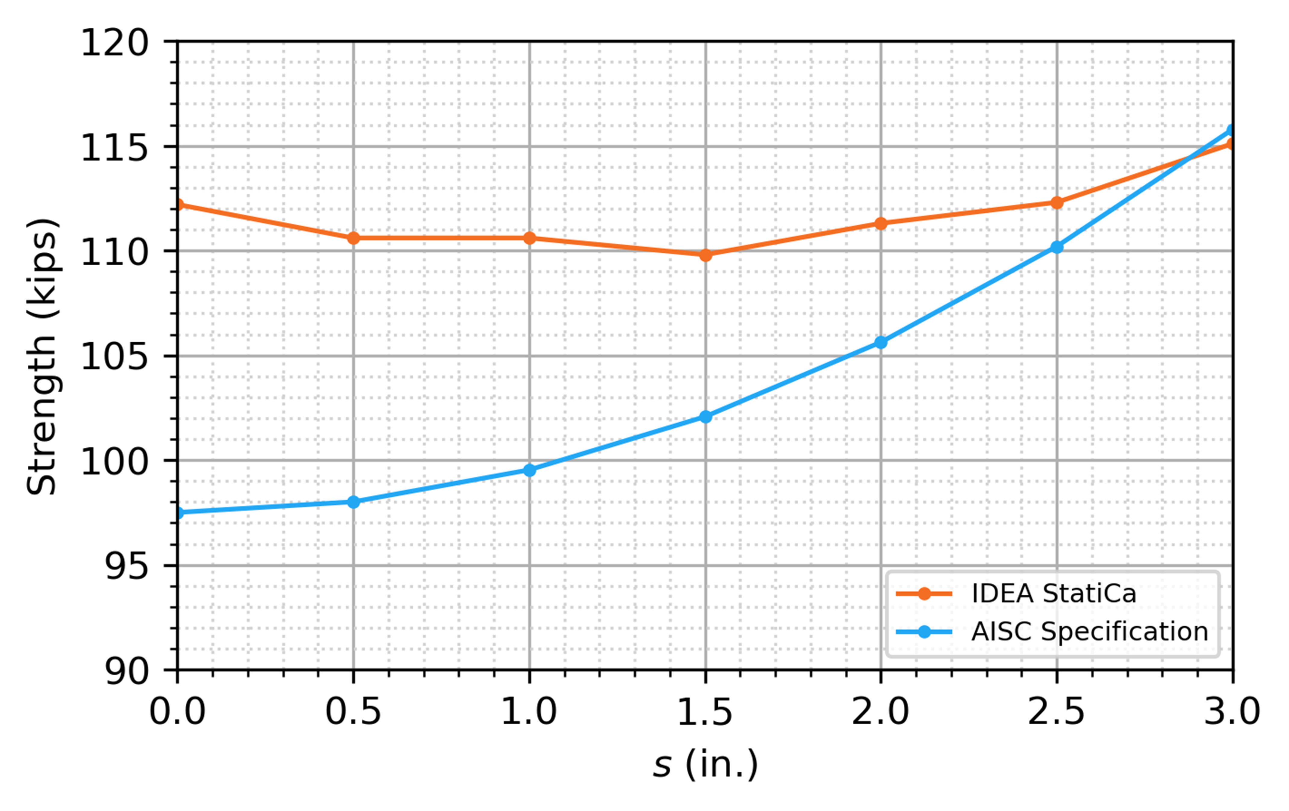
Rezultatele Specificației AISC arată o tendință clară de creștere a rezistenței odată cu dimensiunea s. Rezultatele IDEA StatiCa arată o sensibilitate mai redusă la dimensiunea s, iar rezistența este mai mare decât cea din Specificația AISC pentru toate cazurile, cu excepția cazului s = 3 in. Cu toate acestea, modelul surprinde tiparul de cedare în zigzag așteptat, după cum se demonstrează în figura de mai jos, care prezintă deformația plastică în placa de test la încărcarea aplicată maximă admisă.
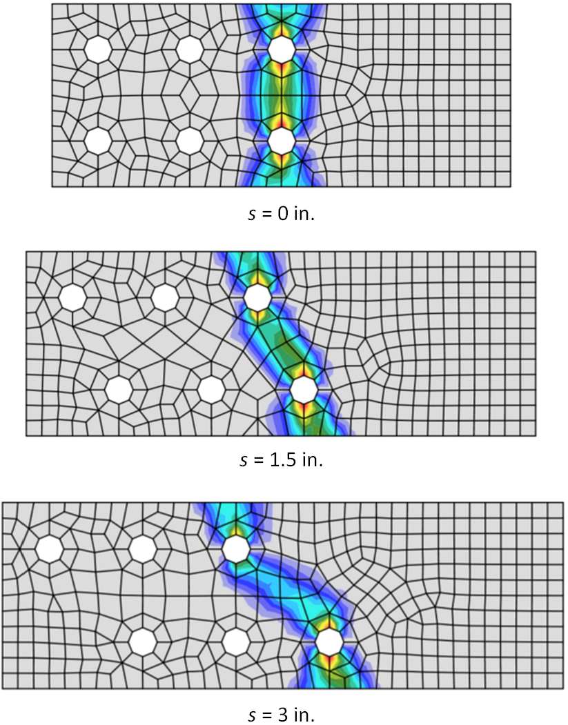
Cerințe privind dimensiunea sudurii de colț
Secțiunea J2.2b din Specificația AISC (2022) include limitări pentru sudurile de colț.
Punctele (a)-(c) ale Secțiunii J2.2b specifică limitări geometrice privind dimensiunea și lungimea minimă a sudurilor de colț. Aceste limitări sunt verificate în timpul calculului dacă opțiunea „Detailing" este bifată în „Code setup". Limitările specifice verificate sunt descrise în acest articol. O sudură nu va trece verificarea conform codului din cauza unei erori de detaliere dacă oricare dintre limitări nu este satisfăcută. Dimensiunile apropiate sau la limită pot să nu fie evaluate conform așteptărilor din cauza preciziei numerice sau a rotunjirii.
Punctul (d) al Secțiunii J2.2b specifică lungimea efectivă a sudurilor de colț, inclusiv reducerile pentru sudurile de colț lungi încărcate la capăt. IDEA StatiCa nu calculează lungimea efectivă pentru sudurile de colț și, prin urmare, nu utilizează prevederile acestui punct, însă efectul distribuției neuniforme a tensiunilor asupra rezistenței sudurilor de colț încărcate la capăt este surprins prin modelarea explicită a rigidității sudurii și a materialului conectat. Consultați acest articol pentru o investigație detaliată a acestei prevederi.
Punctele (e)-(i) ale Secțiunii J2.2b specifică limitări care nu sunt verificate de IDEA StatiCa și, dacă este cazul, trebuie evaluate separat de inginer.
Grosimea de perete de calcul pentru profile HSS
Secțiunea B4.2 din Specificația AISC (2022) impune ca grosimea pereților să fie considerată ca grosime de perete de calcul, t, în calculele de rezistență pentru profile tubulare cu secțiune transversală goală (HSS). Grosimea de perete de calcul este egală cu grosimea nominală, tnom, pentru secțiunile dreptunghiulare și profilele HSS produse conform ASTM A1065/A1065M sau ASTM A1085/A1085M. Grosimea de perete de calcul este egală cu 0,93 ori grosimea nominală a peretelui (adică t = 0,93tnom) pentru alte standarde aprobate pentru utilizare de către Specificație, inclusiv ASTM A500/A500M. ASTM A500 Gr. C este specificația de material preferată în Statele Unite pentru profilele HSS dreptunghiulare și circulare (Tavarez 2022).
IDEA StatiCa nu ajustează automat grosimea peretelui secțiunilor transversale HSS în funcție de material. Prin urmare, utilizatorul trebuie să fie conștient de această cerință și să se asigure că este atribuită grosimea corespunzătoare.
La definirea secțiunii transversale în IDEA StatiCa, secțiunile transversale predefinite din categoria denumită „HSS (AISC 15.0 - A1085, A1065)" au grosimea peretelui egală cu grosimea nominală a peretelui, iar cele din categoria denumită „HSS (AISC 15.0 - A500, A501, A618, A847)" au grosimea peretelui egală cu 0,93 ori grosimea nominală a peretelui.
Referințe
AISC (2022), Specification for Structural Steel Buildings, American Institute of Steel Construction, Chicago, IL.
AISC (2023), Steel Construction Manual, ediția a 16-a, American Institute of Steel Construction, Chicago, IL.
Dowswell, B. (2011). „A Yield Line Component Method for Bolted Flange Connections." Engineering Journal, AISC, 48(trimestrul 2), 93–116.
Dowswell, B. (2015). „Plastic Strength of Connection Elements." AISC Engineering Journal, 52(trimestrul 1), 47–66.
Eatherton, M. R., și Murray, T. M. (2023). End-Plate Moment Connections. Design Guide 39, American Institute of Steel Construction, Chicago, Illinois.
Kulak, G. L., Fisher, J. W., și Struik, J. H. A. (1987). Guide to Design Criteria for Bolted and Riveted Joints, ediția a doua. John Wiley & Sons, Inc.
Miazga, G. S., și D. L. Kennedy. (1989), „Behaviour of fillet welds as a function of the angle of loading," Canadian Journal of Civil Engineering, 16 (4): 583–599.
Muir, L. (2015), „Bear It and Grin" Modern Steel Construction, AISC. (decembrie).
Mohr, B. A., și Murray, T. M. (2008). „Bending Strength of Steel Bracket and Splice Plates." Engineering Journal, AISC, 45(2), 97–106.
Tavarez, J. (2022), „Are You Properly Specifying Materials?" Modern Steel Construction, AISC. (iunie), 16-22.