Echilibru și element de reazem
Element terminat și continuu
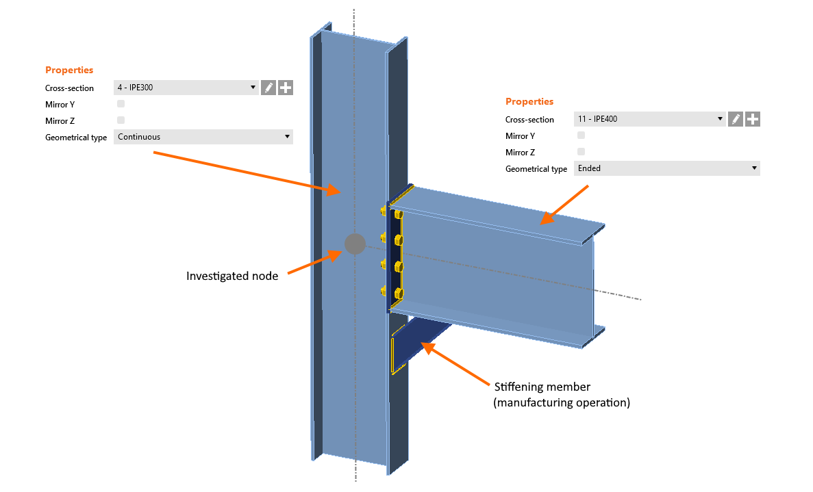
Fiecare element al modelului de îmbinare este definit fie ca Continuu fie ca Terminat în câmpul Tip geometric.
Elementul continuu este considerat a continua mai departe spre nodurile opuse pe ambele laturi, nu există un capăt „conectat" la nodul investigat și ambele capete ale elementului continuu pot fi încărcate.
Tipul terminat este considerat a se termina la nodul investigat: există un capăt conectat și elementul poate fi încărcat doar pe partea opusă (capătul „liber" care, de fapt, continuă mai departe în modelul global).
Notă: Dacă trebuie să definiți un element care este tăiat la ambele capete și nu continuă mai departe în structură, utilizați operația element de rigidizare.
Element de reazem
Un element al nodului este întotdeauna „de reazem" (sau de sprijin) și toate celelalte sunt „conectate". Elementul de reazem este subliniat în lista de elemente din scenă, iar pătrate roșii sunt reprezentate la capetele „continue" ale elementului (ca simbol al rezemării). Elementul de reazem poate fi ales de proiectant dacă este necesar.

Pentru alte simboluri ale condițiilor la limită, consultați articolul despre tipul de model.
Echilibrul încărcărilor
Forțele interioare în fiecare nod al cadrului trebuie să fie în echilibru. În special în cazul unui element continuu, trebuie să introducem cu atenție forțele interioare în toate elementele astfel încât echilibrul să fie menținut în nod.
În definirea Încărcărilor, pot fi alese două opțiuni privind echilibrul.
- Simplificat – pentru acest mod, elementul de reazem este rezemat (element continuu pe ambele capete) și încărcarea nu este definită pe elementul de reazem
- Avansat (implicit) – elementul de reazem este rezemat pe un singur capăt, încărcările sunt aplicate tuturor elementelor și echilibrul forțelor trebuie găsit
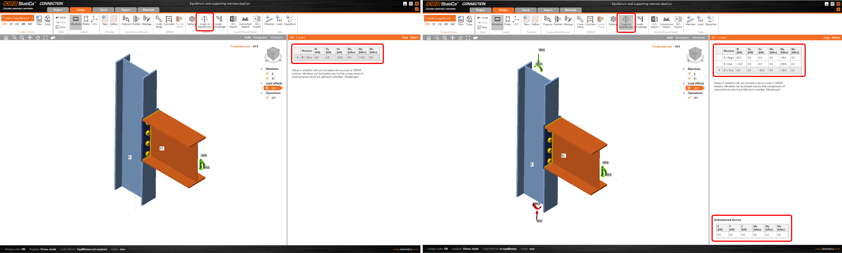
Modul poate fi comutat în bara de sus prin butonul Încărcări în echilibru.
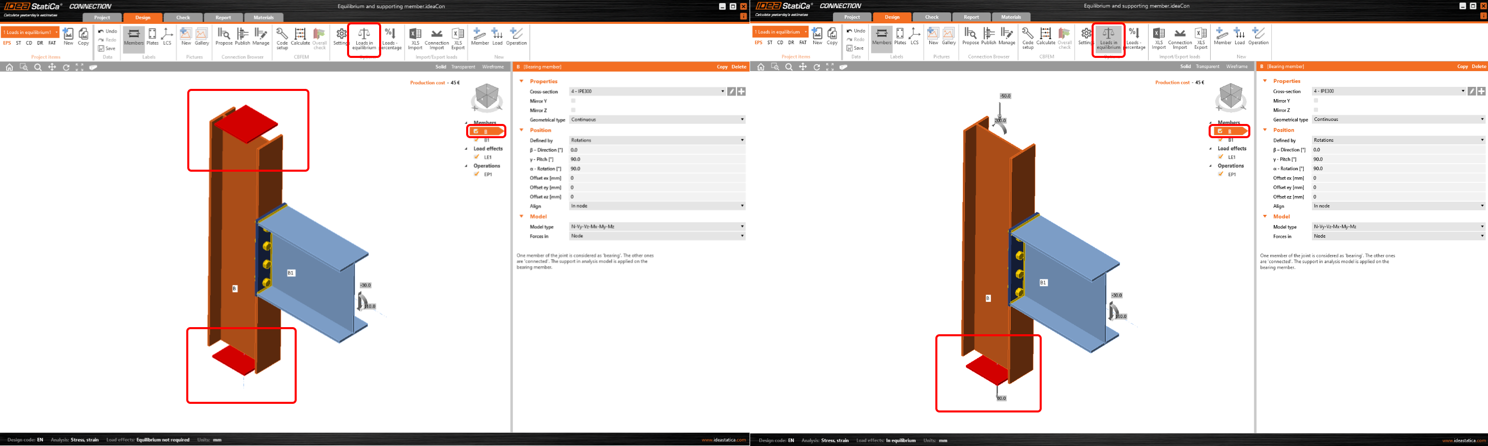
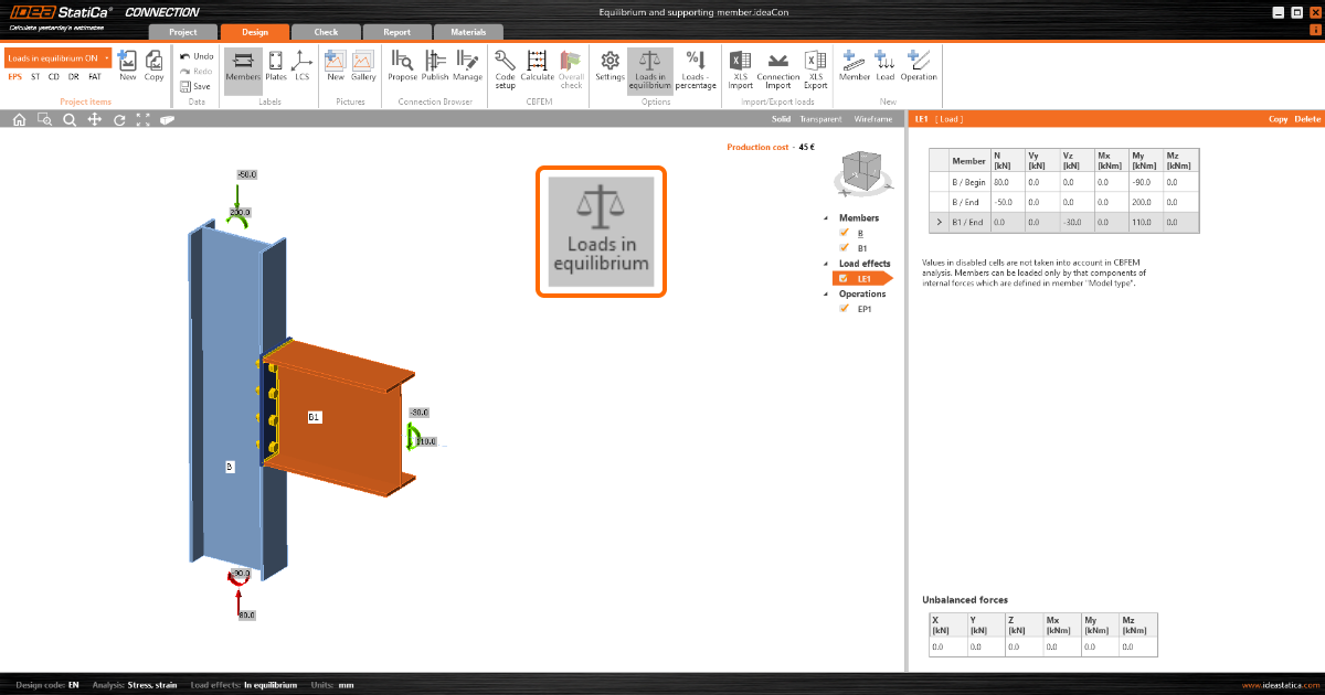
În mod implicit, opțiunea Încărcări în echilibru este activată (începând cu versiunea 22.0 a IDEA StatiCa, consultați secțiunea Note de lansare 22.0). În acest caz, tabelul forțelor dezechilibrate este afișat și utilizatorul este responsabil pentru menținerea încărcărilor în echilibru). Orice forțe dezechilibrate sunt aplicate rezemărilor.
Este important să se conștientizeze că perturbarea condiției de echilibru poate conduce la rezultate false și nesigure. De asemenea, utilizarea metodei simplificate de încărcare (cu Încărcări în echilibru dezactivat) nu ia în considerare imaginea completă a tensiunilor din îmbinare și poate conduce la rezultate false.
Exemplu
Să demonstrăm diferența în următorul exemplu:
Îmbinarea atașată a unei grinzi încărcate (B1) la un stâlp continuu (C) are opțiunea Încărcări în echilibru dezactivată.
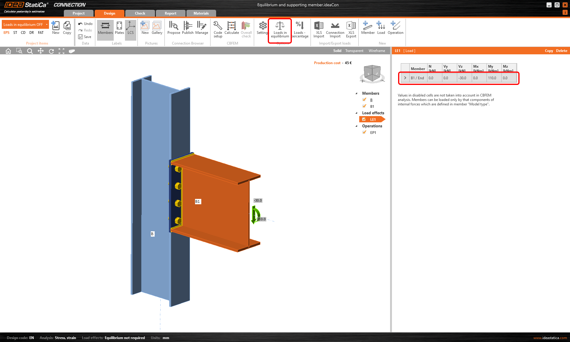
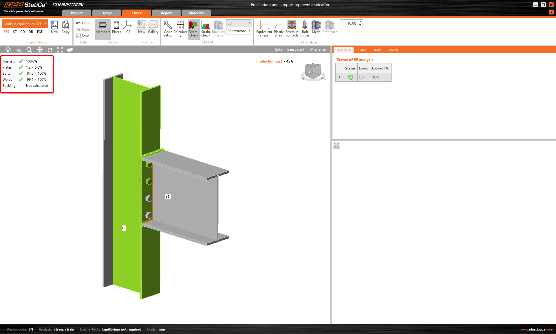
După ce Calculăm proiectul, rezultatele sunt furnizate în scena 3D. Toate verificările efectuate sunt satisfăcătoare.
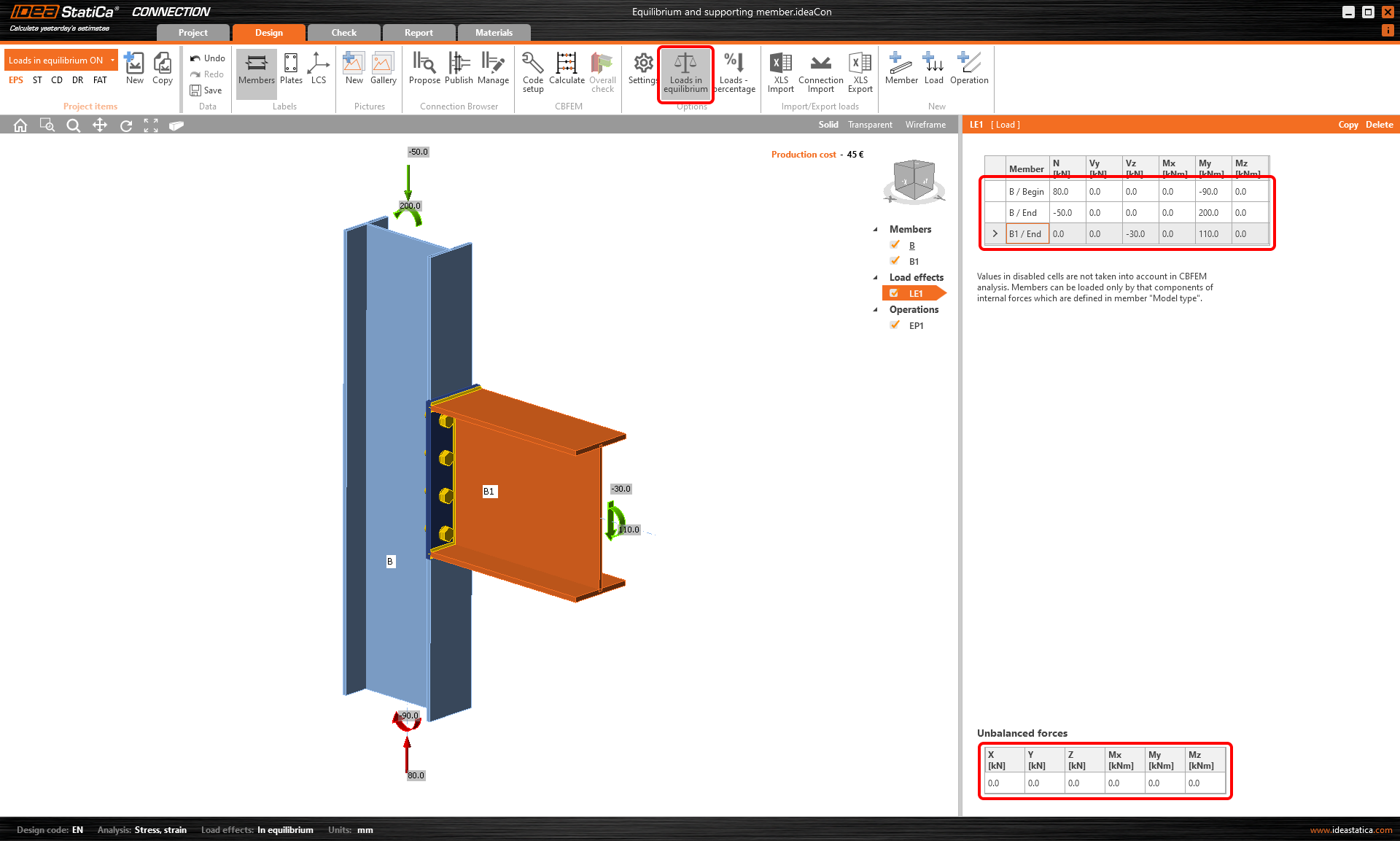
Acum, vom copia proiectul și vom activa Încărcări în echilibru. Apare tabelul cu Forțe dezechilibrate. Putem introduce forțe interioare pe ambele capete ale stâlpului C și verifica echilibrul forțelor nodale introduse.
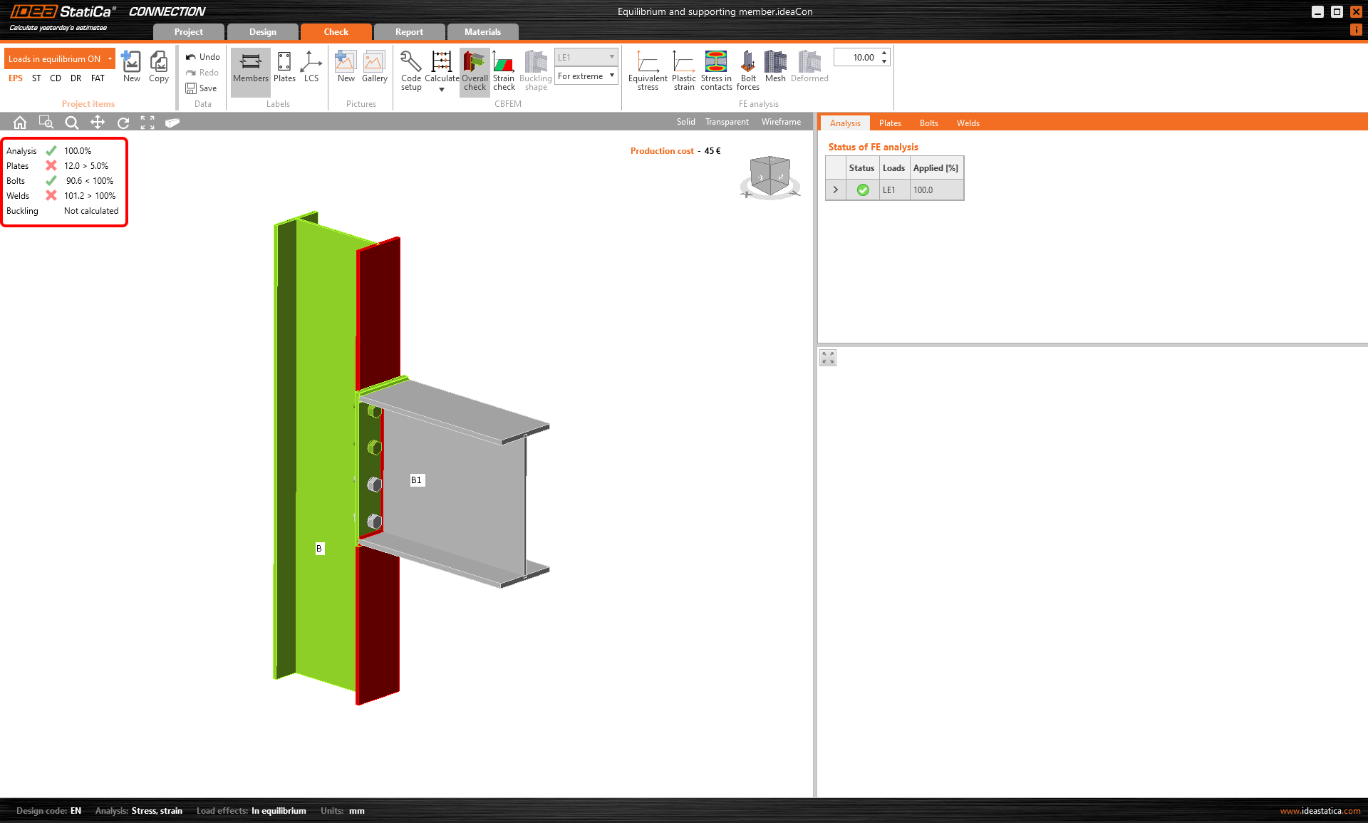
Din nou, Calculăm proiectul CON2 și observăm că sudurile nu au trecut verificarea conform codului. Motivul este acțiunea corectă a încărcării care a adăugat tensiuni în talpa stâlpului, pe care de această dată am luat-o în considerare.
Metoda simplificată
Cerința de echilibru este corectă. Cu toate acestea, nu este necesară pentru proiectarea unor noduri simple. Dacă doar o parte a îmbinării este verificată (cele simple, de ex. o îmbinare grindă-stâlp) și nu suntem interesați de interacțiunea cu încărcarea pe elementul rezemat, există opțiunea de a dezactiva condiția de echilibru. Vă rugăm să faceți acest lucru doar după o analiză atentă.
Înregistrare webinar
Consultați înregistrările webinarelor noastre unde Elementul de reazem și Echilibrul sunt discutate în direct.
Testați astăzi cea mai recentă versiune a IDEA StatiCa
Descărcări atașate
- Equilibrium and supporting member.ideaCon (IDEACON, 61 kB)