Îmbinări cu placă de capăt extinsă pentru momente (AISC)
Acest exemplu de verificare a fost pregătit de Mark D. Denavit și Kayla Truman-Jarrell în cadrul unui proiect comun al Universității din Tennessee și IDEA StatiCa.
1 Descriere
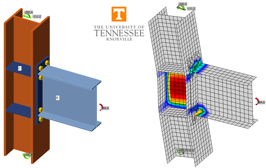
În acest studiu este prezentată o comparație între rezultatele obținute prin metoda elementelor finite bazată pe componente (CBFEM) și metodele tradiționale de calcul utilizate în practica din SUA pentru îmbinările cu placă de capăt extinsă pentru momente (Fig. 1).
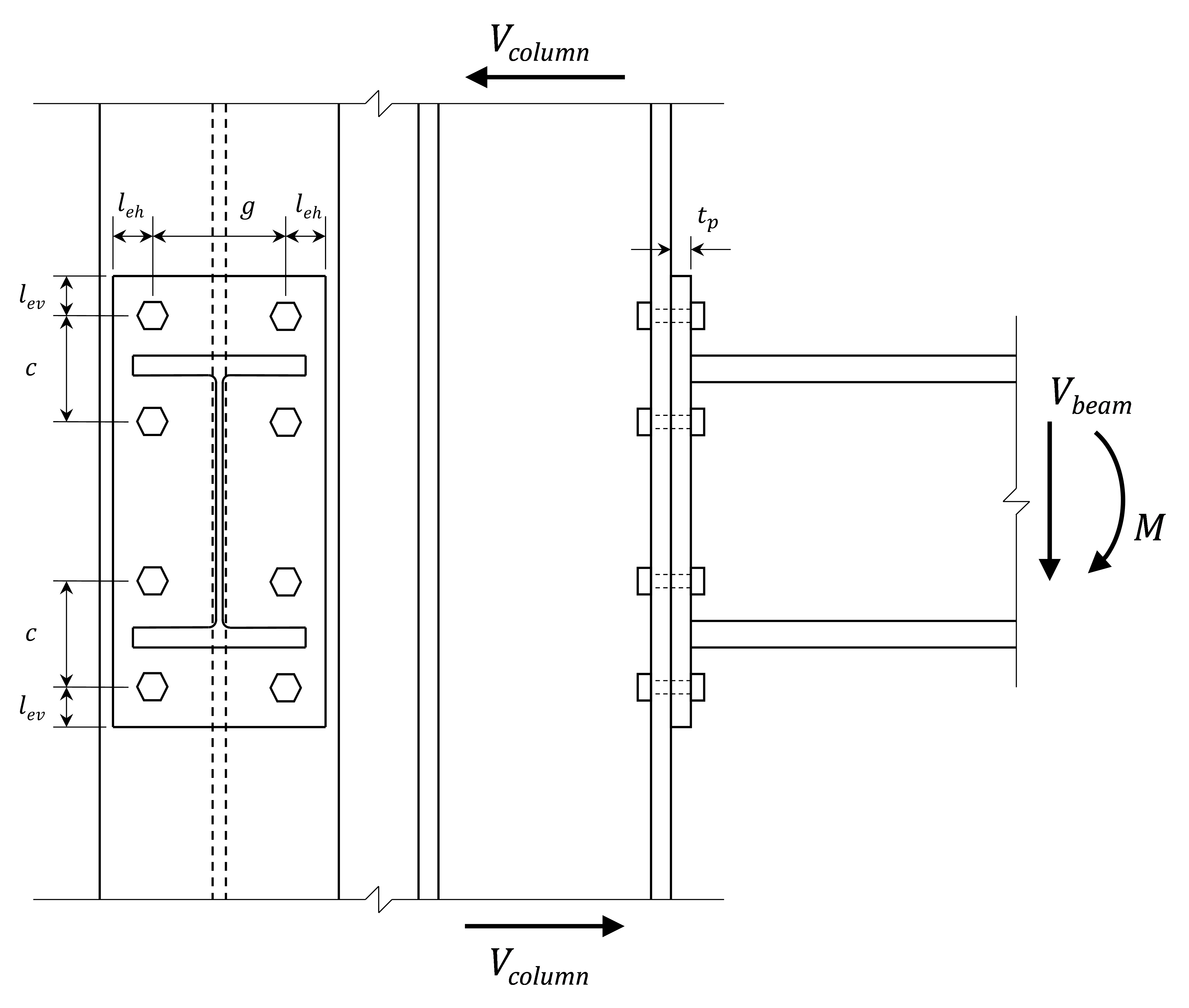
Fig. 1 Schema îmbinării cu placă de capăt extinsă pentru momente investigată în acest studiu
Metodele tradiționale de calcul utilizate în această lucrare pentru îmbinările non-seismice se bazează pe recomandările prezentate în AISC Design Guide 4 (Murray și Sumner 2003), precum și pe cerințele pentru proiectarea pe baza factorilor de încărcare și rezistență (LRFD) din AISC Specification (2016a). Metodele tradiționale de calcul utilizate în această lucrare pentru îmbinările seismice (adică proiectate prin capacitate) se bazează pe AISC Prequalified Connections for Special and Intermediate Steel Moment Frames for Seismic Applications (2016b), denumit în continuare AISC 358. Atât pentru îmbinările seismice, cât și pentru cele non-seismice, aceste referințe includ limitări minime ale grosimii plăcii de capăt și ale grosimii tălpii stâlpului care nu se bazează direct pe încărcările aplicate. Aceste limite sunt destinate să evite efectul de pârghie și să asigure că îmbinarea este complet rigidizată. Pentru îmbinările non-seismice, este permisă utilizarea unor plăci și tălpi de stâlp mai subțiri dacă se ia în considerare efectul de pârghie, de exemplu folosind recomandările din Dowswell (2011). Cu toate acestea, limitele minime de grosime au fost respectate pentru toate calculele tradiționale din acest studiu.
Stările limită evaluate în calculele tradiționale includ ruperea la întindere a șuruburilor, curgerea la încovoiere a plăcii de capăt și a tălpii stâlpului (prin limitări de grosime), curgerea la forfecare și ruperea plăcii de capăt, stările limită locale ale stâlpului (adică curgerea locală a inimii, strivirea locală a inimii și flambajul inimii la compresiune), curgerea zonei de nod a inimii stâlpului, stările limită la forfecare ale șuruburilor (adică ruperea la forfecare a șuruburilor, presiunea de contact, smulgerea – de remarcat că s-a luat în considerare doar rezistența la forfecare a șuruburilor de compresiune). Pentru simplitate, toate sudurile au fost modelate ca suduri cap la cap, iar rezistența acestora nu a fost evaluată în calculele tradiționale.
Rezultatele CBFEM au fost obținute din IDEA StatiCa Versiunea 21.0. Exemple de modele sunt prezentate în Fig. 2. Încărcările maxime admise au fost determinate iterativ prin ajustarea valorii încărcării aplicate la o valoare pe care programul o consideră sigură, dar dacă ar fi mărită cu o cantitate mică (de ex., 1 kip-in.), programul ar considera-o nesigură. Spre deosebire de calculele tradiționale, influența efectului de pârghie a fost evaluată în IDEA StatiCa, iar rezultatele prezentate includ cazuri cu efect de pârghie. Rigiditatea îmbinării a fost evaluată prin analize de rigiditate (adică tipul de analiză „ST").
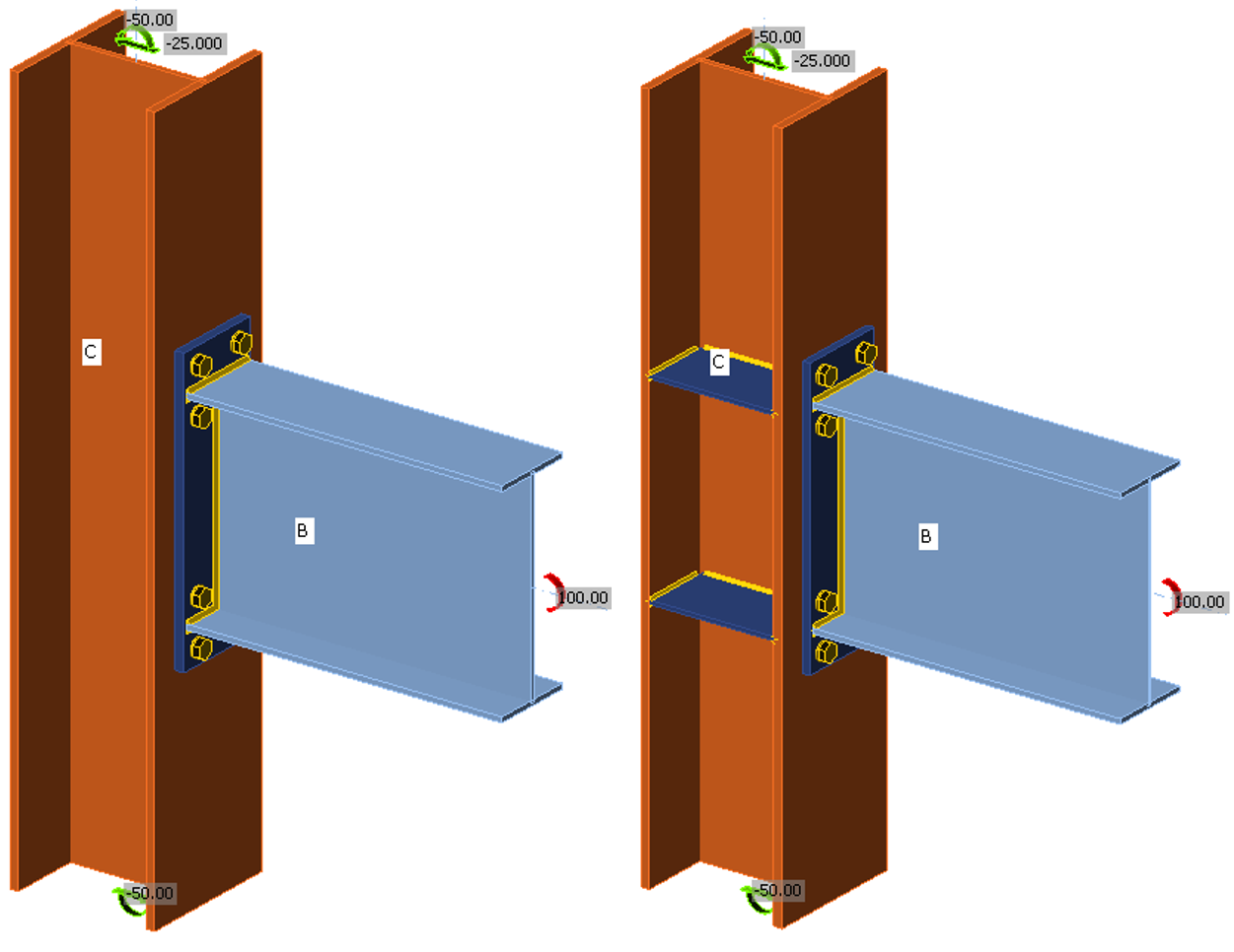
Fig. 2 Îmbinări cu placă de capăt extinsă pentru momente modelate în IDEA StatiCa.
2 Grosimea plăcii de capăt
În primul rând, se investighează impactul grosimii plăcii de capăt asupra comportamentului și rezistenței îmbinării. Pentru aceste comparații, grinda este un profil W21×68, iar stâlpul este un profil W14×193. Ambele sunt conforme cu ASTM A992 (Fy = 50 ksi, Fu = 65 ksi). Stâlpul a fost ales să fie de dimensiuni mari (tf = 1,44 in.) și prevăzut cu elemente de rigidizare de 5/8 in. grosime (adică plăci de continuitate) pentru a se asigura că starea limită determinantă nu se află în stâlp. Placa de capăt are o înălțime de 29 in., o lățime de 9,5 in., iar grosimea variază de la 3/8 in. la 2,5 in. Toate materialele de placă (adică placa de capăt și elementele de rigidizare) sunt conforme cu ASTM A572 Gr. 50 (Fy = 50 ksi, Fu = 65 ksi). Îmbinarea are patru șuruburi în apropierea fiecărei tălpi a grinzii (8 șuruburi în total), iar placa de capăt nu este rigidizată. Această configurație este denumită în mod obișnuit configurație cu patru șuruburi nerigidizată, 4E. Șuruburile au diametrul de 1-1/8 in., tip A325, cu un ecartament orizontal de g = 5,5 in. și o distanță verticală de c = 4,5 in. Distanța verticală de la axa șuruburilor până la marginea plăcii de capăt este lev = 2 in.
În IDEA StatiCa, încărcările au fost aplicate folosind opțiunea „încărcări în echilibru". Momentele aplicate la partea superioară și la partea inferioară a stâlpului erau fiecare egale cu jumătate din momentul aplicat grinzii. O forță tăietoare de 25 kips a fost de asemenea aplicată stâlpului (Vcolumn = 25 kips, Fig. 1). Pentru simplitate, nu s-a aplicat nicio forță tăietoare grinzii (Vbeam = 0 kips, Fig. 1).
Variația momentului maxim aplicat în funcție de grosimea plăcii de capăt este prezentată în Fig. 3. Starea limită determinantă pentru fiecare grosime este prezentată în Tabelul 1. Rezultatele nu sunt prezentate pentru calculele tradiționale pentru grosimi ale plăcii de capăt mai mici de 1 in., deoarece plăcile mai subțiri nu îndeplineau cerințele minime de grosime pentru a evita efectul de pârghie. Starea limită determinantă din calculele tradiționale pentru îmbinările care îndeplineau cerința de grosime a plăcii de capăt a fost ruperea la întindere a șuruburilor. Ca urmare, momentul maxim aplicat nu variază cu grosimea plăcii de capăt.
Variația momentului maxim aplicat în funcție de grosimea plăcii de capăt se observă în rezultatele IDEA StatiCa. Pentru plăci foarte subțiri (t ≤ 0,5 in.), deformația plastică în placa de capăt controlează proiectarea. În caz contrar, întinderea șuruburilor controlează proiectarea. Momentul maxim aplicat crește odată cu creșterea grosimii plăcii de capăt pe întregul interval investigat. Creșterea momentului maxim aplicat este rapidă pentru plăci subțiri, deoarece creșterea grosimii mărește direct rezistența la curgere prin încovoiere a plăcii de capăt. Creșterea momentului maxim aplicat este mai graduală atunci când întinderea șuruburilor controlează. Pentru grosimi ale plăcii de capăt de 1,25 in. și mai mari, momentul maxim aplicat pentru IDEA StatiCa depășește cel din calculele tradiționale. Motivul este că calculele tradiționale presupun că forța de contact la interfața dintre talpa stâlpului și placa de capăt este centrată față de talpa grinzii, în timp ce IDEA StatiCa modelează explicit presiunea de contact. Pe măsură ce grosimea plăcii de capăt crește, porțiunea plăcii de capăt care se extinde dincolo de talpa grinzii este mai rigidă și mai capabilă să reziste presiunii de contact, deplasând forța de compresiune sub talpa inferioară a grinzii (Fig. 4). Prin urmare, deși capacitatea la întindere a șuruburilor este aceeași atât în IDEA StatiCa, cât și în calculele tradiționale, brațul de pârghie al cuplului este mai mare în IDEA StatiCa, rezultând o capacitate la moment mai mare.
Pentru fiecare grosime a plăcii de capăt, prezența efectului de pârghie și rigiditatea îmbinării au fost determinate de IDEA StatiCa. S-a considerat că o îmbinare prezintă efect de pârghie dacă exista tensiune de contact pe partea întinsă a îmbinării. De exemplu, după cum se arată în Fig. 4, efectul de pârghie a fost observat pentru îmbinarea cu o placă de 7/8 in. grosime, dar nu și pentru îmbinarea cu placa de 2-1/2 in. grosime. Nu a existat efect de pârghie pentru grosimi ale plăcii de capăt de 1 in. și mai mari. Aceasta este în concordanță cu limitarea minimă de grosime corespunzătoare din calculele tradiționale. Îmbinările cu grosimi ale plăcii de capăt de 7/8 in. și mai mari au fost determinate ca fiind complet rigide (adică rigide) printr-o analiză de rigiditate în IDEA StatiCa, indicând că limitarea minimă de grosime din calculele tradiționale oferă, de asemenea, o verificare indirectă bună a rigidității îmbinării pentru acest caz.
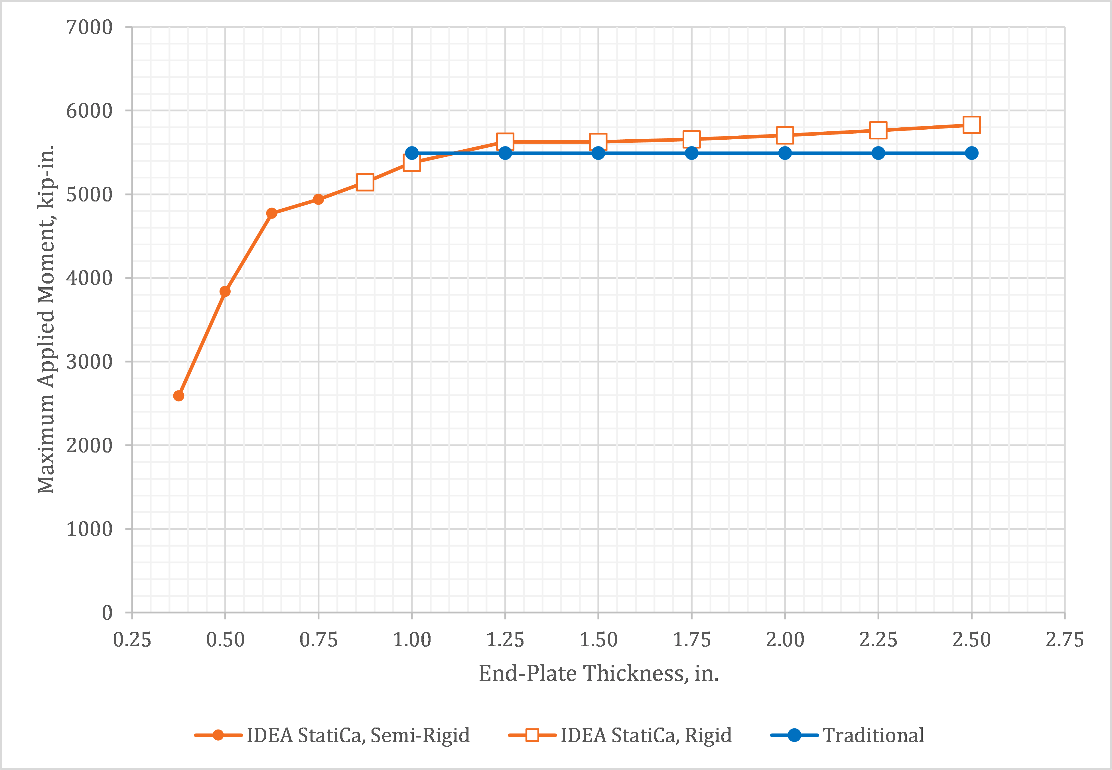
Fig. 3 Momentul maxim aplicat vs. grosimea plăcii de capăt
Tabelul 1. Starea limită determinantă pentru rezultatele prezentate în Fig. 3
| Grosimea plăcii de capăt, in. | IDEA StatiCa | Tradițional |
| 0,375 | Deformație plastică (placă de capăt) | N/A |
| 0,500 | Deformație plastică (placă de capăt) | N/A |
| 0,625 | Întinderea șuruburilor | N/A |
| 0,750 | Întinderea șuruburilor | N/A |
| 0,875 | Întinderea șuruburilor | N/A |
| 1,000 | Întinderea șuruburilor | Întinderea șuruburilor |
| 1,250 | Întinderea șuruburilor | Întinderea șuruburilor |
| 1,500 | Întinderea șuruburilor | Întinderea șuruburilor |
| 1,750 | Întinderea șuruburilor | Întinderea șuruburilor |
| 2,000 | Întinderea șuruburilor | Întinderea șuruburilor |
| 2,250 | Întinderea șuruburilor | Întinderea șuruburilor |
| 2,500 | Întinderea șuruburilor | Întinderea șuruburilor |
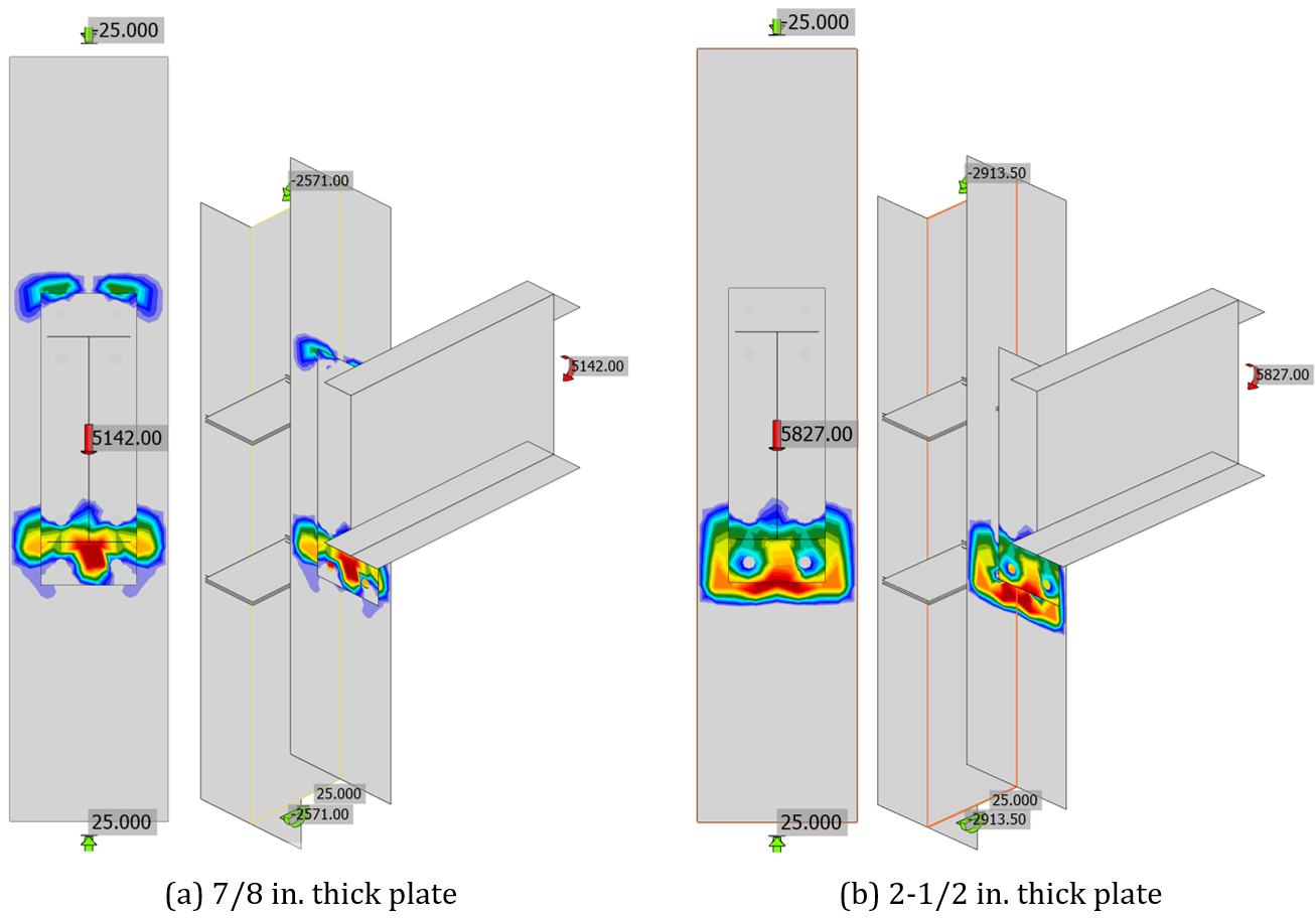
Fig. 4 Tensiunea de contact pentru rezultatele prezentate în Fig. 3
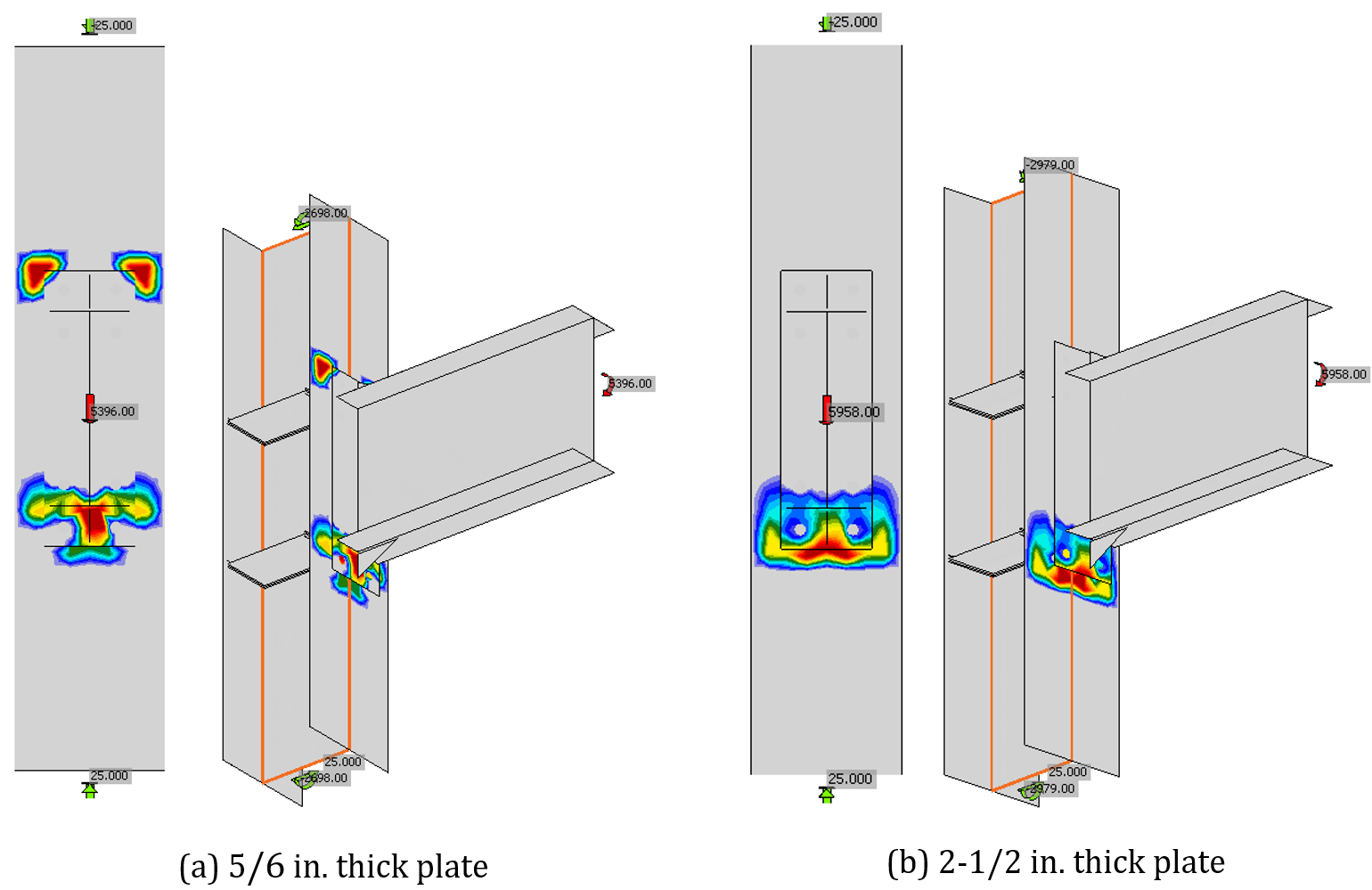
Fig. 5 Tensiunea de contact pentru rezultatele prezentate în Fig. 6 (cu element de rigidizare al plăcii de capăt)
Adăugarea elementelor de rigidizare la placa de capăt modifică comportamentul îmbinării. Variația momentului maxim aplicat în funcție de grosimea plăcii de capăt este prezentată în Fig. 6 pentru aceleași îmbinări investigate anterior, dar cu elemente de rigidizare ale plăcii de capăt adăugate. Rezultatele IDEA StatiCa prezentate în Fig. 3 pentru îmbinările fără elemente de rigidizare sunt incluse în Fig. 6 pentru referință. Elementele de rigidizare aveau grosimea de 1/2 in., lățimea de 3,5 in., lungimea de 6,5 in. și au fost plasate pe ambele tălpi ale grinzii. Materialul plăcii pentru elementele de rigidizare era conform cu ASTM A572 Gr. 50 (Fy = 50 ksi, Fu = 65 ksi).
Pentru calculele tradiționale, adăugarea elementelor de rigidizare modifică modelul liniei de curgere pentru rezistența la încovoiere a plăcii de capăt, reducând grosimea minimă. Cu toate acestea, adăugarea elementelor de rigidizare nu a modificat rezistența îmbinării, care a rămas controlată de ruperea la întindere a șuruburilor, deoarece forța de compresiune este presupusă a fi centrată față de talpă indiferent de rigiditatea plăcii de capăt. O analiză a cercetărilor recente a confirmat că forța de compresiune se deplasează sub talpa inferioară odată cu adăugarea elementelor de rigidizare ale plăcii de capăt și a fost propusă o metodă de luare în considerare a acestei deplasări în proiectare (Landolfo et al. 2018).
Pentru IDEA StatiCa, adăugarea elementelor de rigidizare a crescut încărcarea maximă aplicată. Limitele determinante au fost aceleași cu cele prezentate în Tabelul 1. Creșterea încărcărilor maxime aplicate a fost cea mai mare pentru grosimi ale plăcii de capăt între 5/8 in. și 1 in., unde întinderea șuruburilor a controlat, iar elementele de rigidizare au contribuit la reducerea efectului de pârghie și la creșterea brațului de pârghie al cuplului de forțe.
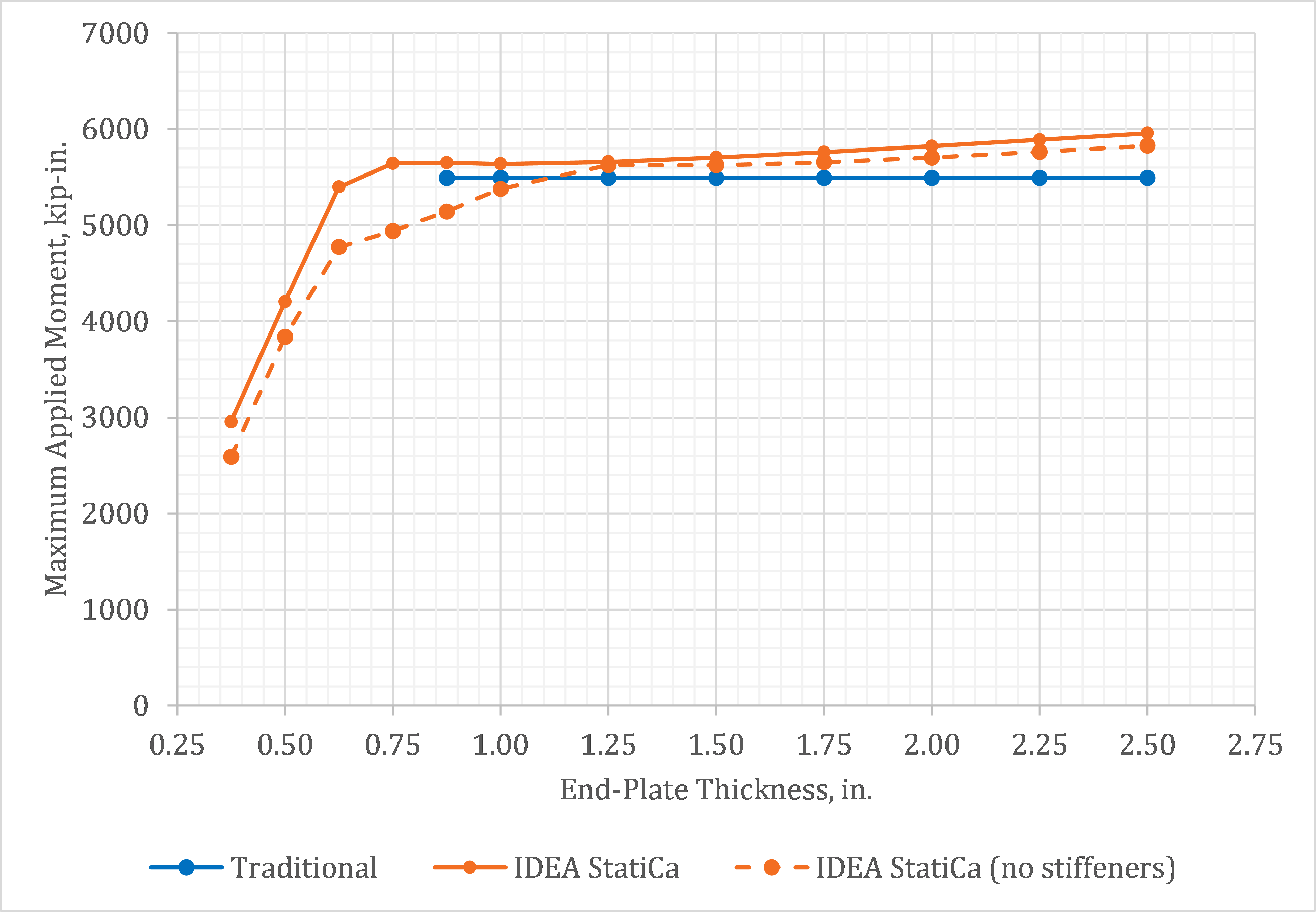
Fig. 6 Momentul maxim aplicat vs. grosimea plăcii de capăt
Toate analizele precedente au utilizat un stâlp relativ mare pentru a se asigura că stările limită ale stâlpului nu controlează. Stâlpul pentru analizele următoare a fost mai mic, un profil W14×109. Celelalte aspecte ale îmbinărilor, inclusiv grosimea elementelor de rigidizare ale stâlpului, grinda, placa de capăt și șuruburile au rămas aceleași. Placa de capăt pentru aceste analize nu a fost rigidizată.
Variația momentului maxim aplicat în funcție de grosimea plăcii de capăt este prezentată în Fig. 8. Starea limită determinantă pentru fiecare grosime este prezentată în Tabelul 2. În această figură sunt trasate mai multe linii atât pentru IDEA StatiCa, cât și pentru calculele tradiționale.
Pentru calculele tradiționale, rezultatele sunt trasate pentru cazul în care efectul deformațiilor inelastice ale zonei de nod asupra stabilității cadrului nu este luat în considerare în analiza cadrului și pentru cazul în care efectul este luat în considerare în analiza cadrului. Curgerea zonei de nod afectează rigiditatea globală a cadrului și poate crește semnificativ efectele de ordinul doi. Dacă inelasticitatea zonei de nod nu este luată în considerare în analiză pentru determinarea rezistențelor necesare ale cadrului, AISC Specification (2016a) limitează comportamentul zonei de nod la domeniul elastic. Dacă inelasticitatea zonei de nod este luată în considerare la determinarea rezistențelor necesare ale cadrului, se recunoaște rezistența suplimentară la forfecare inelastică a zonei de nod.
În cazul în care inelasticitatea zonei de nod nu este luată în considerare în analiză, rezistența la forfecare a zonei de nod controlează rezistența îmbinării, cu un moment maxim aplicat de 4.649 kip-in. În cazul în care inelasticitatea zonei de nod este luată în considerare în analiză, rezistența la întindere a șuruburilor controlează rezistența îmbinării, cu un moment maxim aplicat de 5.490 kip-in. (de remarcat că momentul maxim aplicat pentru curgerea zonei de nod este doar ușor mai mare, de 5.495 kip-in.).
Limita determinantă pentru IDEA StatiCa este limita de deformație plastică în placa de capăt pentru plăci de capăt foarte subțiri (t ≤ 0,5 in.) și întinderea șuruburilor în rest. Momentul maxim aplicat este mai mare pentru IDEA StatiCa decât pentru calculele tradiționale. Stările limită determinante diferă, de asemenea, astfel că au fost efectuate analize suplimentare pentru a cuantifica momentul aplicat la care se atinge limita de deformație plastică pentru zona de nod a inimii stâlpului, prezentată în Fig. 7 pentru o grosime a plăcii de 1,25 in. Aceste valori sunt reprezentate ca linie întreruptă în Fig. 8 (de remarcat că limitele de rezistență ale șuruburilor au fost depășite pentru aceste analize).
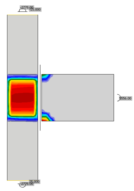
Fig. 7 Deformație plastică în zona de nod pentru tp = 1,25 in.
IDEA StatiCa surprinde starea limită de curgere a zonei de nod, deși cu o rezistență mai mare decât cea permisă de AISC Specification (2016a) atunci când efectul deformațiilor inelastice ale zonei de nod asupra stabilității cadrului este luat în considerare în analiză. Îmbinările pot fi proiectate în IDEA StatiCa pentru a limita curgerea zonei de nod pur și simplu prin impunerea unei limite de deformație plastică mai mică de 5%. De exemplu, încărcarea maximă aplicată pentru îmbinarea cu o placă de capăt de 1,75 in. grosime pentru a avea un comportament aproape elastic (adică limita de 0,1% deformație plastică) al inimii stâlpului este de 4.418 kip-in., ceea ce se compară bine cu momentul maxim aplicat de 4.649 kip-in. din calculele tradiționale atunci când efectul deformațiilor inelastice ale zonei de nod asupra stabilității cadrului nu este luat în considerare în analiză.
Interesant, efectul de pârghie este identificat și îmbinarea este clasificată ca parțial rigidă (semi-rigidă) în IDEA StatiCa pentru grosimi ale plăcii de capăt de până la 1,5 in. Calculele tradiționale permit grosimi ale plăcii de capăt de până la 1 in. cu ipoteza absenței efectului de pârghie.
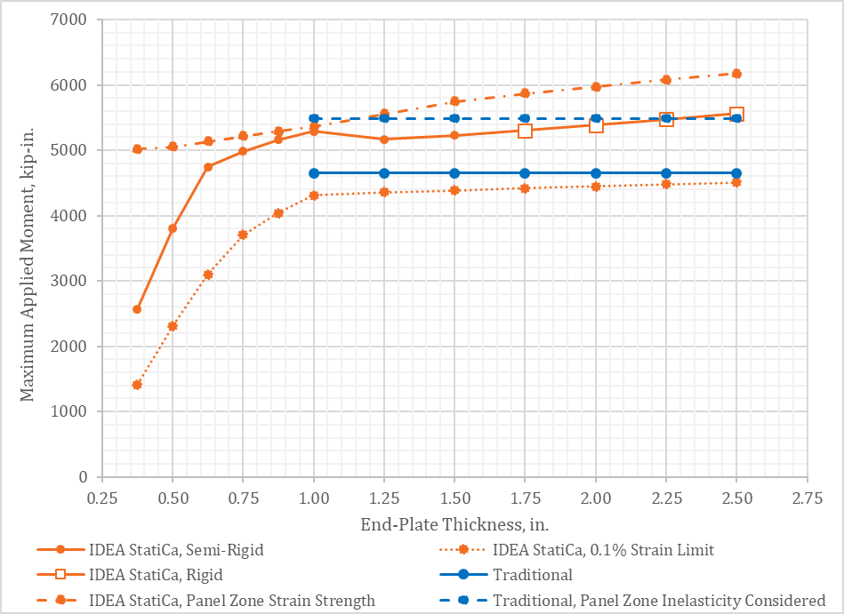
Fig. 8 Momentul maxim aplicat vs. grosimea plăcii de capăt
Tabelul 2. Starea limită determinantă pentru rezultatele prezentate în Fig. 8
| Grosimea plăcii de capăt, in. | IDEA StatiCa | Tradițional 1 | Tradițional 2 |
| 0,375 | Deformație plastică (placă de capăt) | N/A | N/A |
| 0,500 | Deformație plastică (placă de capăt) | N/A | N/A |
| 0,625 | Întinderea șuruburilor | N/A | N/A |
| 0,750 | Întinderea șuruburilor | N/A | N/A |
| 0,875 | Întinderea șuruburilor | N/A | N/A |
| 1,000 | Întinderea șuruburilor | Forfecare zonă de nod | Întinderea șuruburilor |
| 1,250 | Întinderea șuruburilor | Forfecare zonă de nod | Întinderea șuruburilor |
| 1,500 | Întinderea șuruburilor | Forfecare zonă de nod | Întinderea șuruburilor |
| 1,750 | Întinderea șuruburilor | Forfecare zonă de nod | Întinderea șuruburilor |
| 2,000 | Întinderea șuruburilor | Forfecare zonă de nod | Întinderea șuruburilor |
| 2,250 | Întinderea șuruburilor | Forfecare zonă de nod | Întinderea șuruburilor |
| 2,500 | Întinderea șuruburilor | Forfecare zonă de nod | Întinderea șuruburilor |
1 Efectul deformațiilor inelastice ale zonei de nod asupra stabilității cadrului nu este luat în considerare în analiză
2 Efectul deformațiilor inelastice ale zonei de nod asupra stabilității cadrului este luat în considerare în analiză
3 Distanța verticală dintre șuruburi
Grosimea nu este singurul parametru care influențează comportamentul plăcii de capăt. Pe măsură ce distanța verticală dintre axele șuruburilor crește, crește și pasul (distanța de la fața tălpii grinzii până la axa celui mai apropiat șurub). În general, cel mai mic pas posibil al șuruburilor este cel mai economic (Murray și Sumner 2003), însă valori mai mari pot fi necesare din considerente de execuție sau din alte motive.
Se efectuează o serie de analize cu distanțe verticale variabile între șuruburi. Pentru aceste comparații, grinda este un profil W21×55, iar stâlpul este un profil W14×109. Ambele sunt conforme cu ASTM A992 (Fy = 50 ksi, Fu = 65 ksi). Placa de capăt are o înălțime de 28,5 in., o lățime de 9,0 in., o grosime de 1 in. și este conformă cu ASTM A572 Gr. 50 (Fy = 50 ksi, Fu = 65 ksi). Îmbinarea are patru șuruburi în apropierea fiecărei tălpi a grinzii (8 șuruburi în total), iar placa de capăt nu este rigidizată. Șuruburile au diametrul de 1 in., tip A325, cu un ecartament orizontal de 5,5 in. Distanța verticală dintre șuruburi variază de la 3,5 in. la 6 in., iar distanța de la axa șuruburilor până la marginea plăcii de capăt variază de la 2,5 in. la 1,25 in. Centrul de greutate al grupului de șuruburi a fost menținut constant. Încărcările au fost aplicate conform descrierii din secțiunea anterioară, inclusiv o forță tăietoare de 25 kips în stâlp.
Variația momentului maxim aplicat în funcție de distanța verticală dintre șuruburi este prezentată în Fig. 9. Starea limită determinantă atât pentru calculele tradiționale, cât și pentru IDEA StatiCa a fost ruperea la întindere a șuruburilor pentru toate cazurile. Pentru distanțe verticale între șuruburi mai mici sau egale cu 5 in., există o concordanță bună între calculele tradiționale și IDEA StatiCa. Pentru distanțe verticale mai mari, încărcarea maximă aplicată din IDEA StatiCa scade. Încărcarea maximă aplicată din calculele tradiționale este constantă pe întregul interval. Motivul discrepanței este efectul de pârghie. Grosimea plăcii îndeplinește cerința minimă de grosime din calculele tradiționale pentru a presupune absența efectului de pârghie. Cu toate acestea, efectul de pârghie este observat în rezultatele IDEA StatiCa pentru distanțe verticale între șuruburi de 5,5 in. și 6 in., reducând momentul maxim aplicat.

Fig. 9 Momentul maxim aplicat vs. distanța verticală dintre șuruburi
4 Proiectare prin capacitate
Îmbinările cu placă de capăt extinsă pentru momente reprezintă unul dintre tipurile de îmbinări precalificate pentru utilizare în cadre metalice cu moment special și intermediar (AISC 2016b). Cu toate acestea, acestea sunt precalificate doar dacă îndeplinesc limitările și au fost proiectate conform procedurii înalt prescriptive din AISC 358. Criteriile de proiectare din AISC 358 sunt destinate să asigure că deformarea inelastică a îmbinării este realizată prin curgerea grinzii.
Utilizarea IDEA StatiCa în locul procedurii de proiectare specificate în AISC 358 nu este permisă pentru demonstrarea conformității cu cerințele pentru îmbinările grindă-stâlp în cadre metalice cu moment special și intermediar. Cu toate acestea, IDEA StatiCa are capacitatea de a efectua proiectarea prin capacitate și de a produce rezultate comparabile.
Pentru proiectarea prin capacitate în IDEA StatiCa, anumite elemente sunt desemnate ca componente disipative. Răspunsul tensiune-deformație al acestor componente este înlocuit pentru a se baza pe rezistențele așteptate ale materialului și pentru a include ecruisarea. Apoi, se aplică încărcări corespunzătoare efectelor maxime probabile ale încărcărilor. Pentru îmbinarea cu placă de capăt extinsă pentru momente, grinda este componenta disipativă, iar efectele maxime probabile ale încărcărilor sunt calculate conform AISC 358.
În această investigație, o serie de îmbinări sunt proiectate prin capacitate conform procedurii AISC 358 și IDEA StatiCa pentru a compara rezultatele. De remarcat că factorii de rezistență impliciți au fost înlocuiți în IDEA StatiCa pentru a corespunde celor specificați în AISC 358. Grinda variază de la un profil W18×35 la un profil W18×60, stâlpul este un profil W14×211. Toate profilele cu tălpi late sunt conforme cu ASTM A992 (Fy = 50 ksi, Ry = 1,1, Fu = 65 ksi). Placa de capăt este conformă cu ASTM A572 Gr. 50 (Fy = 50 ksi, Fu = 65 ksi) și are o înălțime de 28 in. Lățimea plăcii a fost de 7 in. pentru grinzile W18x35, W18x40 și W18x46 și de 8,5 in. pentru grinzile W18x50, W18x55 și W18x60. Grosimea plăcii de capăt a fost selectată în cadrul procesului de proiectare. A fost utilizată o configurație cu patru șuruburi nerigidizată, 4E, cu șuruburi A490. Diametrul șuruburilor a fost selectat în cadrul procesului de proiectare. Ecartamentul orizontal a fost de 5,5 in., distanța verticală dintre șuruburi a fost de 5,5 in., iar distanța verticală de la axa șuruburilor până la marginea plăcii de capăt a fost lev = 2 in.
Momentul aplicat și forța tăietoare aplicată grinzii pentru fiecare secțiune de grindă sunt prezentate în Tabelul 3. Forța tăietoare aplicată grinzii s-a bazat pe o forță tăietoare presupusă rezultată din încărcări gravitaționale de 30 kips și o lungime a grinzii (între axele stâlpilor) de 30 ft. Încărcările au fost aplicate la „poziția X" (adică distanța de la axa stâlpului până la locația presupusă a articulației plastice). O forță tăietoare de 30 kips a fost de asemenea aplicată stâlpului. Interesant, deformațiile plastice în grindă au atins un maxim de aproximativ 10% în aceste analize. Cu toate acestea, acest nivel ridicat de deformație plastică nu depășește nicio limită, deoarece grinda este clasificată ca componentă disipativă.
Tabelul 3. Încărcări aplicate pentru exemplul de proiectare prin capacitate
| Secțiunea grinzii | Moment aplicat, kip-in | Forță tăietoare aplicată grinzii, kip | Poziția X, in |
| W18X35 | 4.206 | 55,8 | 16,70 |
| W18X40 | 4.959 | 60,4 | 16,80 |
| W18X46 | 5.737 | 65,2 | 16,90 |
| W18X50 | 6.388 | 69,2 | 16,85 |
| W18X55 | 7.084 | 73,4 | 16,90 |
| W18X60 | 7.780 | 77,7 | 16,95 |
Grosimea plăcii de capăt proiectată și diametrul șuruburilor sunt prezentate în funcție de greutatea grinzii în Fig. 10 și, respectiv, Fig. 11. Este prezentată câte o proiectare pentru fiecare dimensiune de grindă pentru calculele tradiționale, deoarece procedura AISC 358 inhibă efectul de pârghie și conduce la o proiectare unică eficientă. Sunt prezentate două proiectări pentru fiecare dimensiune de grindă pentru IDEA StatiCa. Datorită capacității de a lua în considerare explicit efectul de pârghie în IDEA StatiCa, sunt posibile o gamă de proiectări eficiente în funcție de prioritatea relativă a diametrului șuruburilor și a grosimii plăcii. A fost efectuată o optimizare informală pentru a determina o proiectare în care grosimea plăcii a fost minimizată și alta în care diametrul șuruburilor a fost minimizat.
Când diametrul șuruburilor este minimizat, diametrul rezultat al șuruburilor este același între calculele tradiționale și IDEA StatiCa, dar grosimea plăcii este mai mare pentru proiectarea IDEA StatiCa. Plăcile mai groase sunt necesare în IDEA StatiCa pentru a elimina efectul de pârghie și a minimiza solicitarea șuruburilor.
Când grosimea plăcii este minimizată, grosimea rezultată a plăcii pentru proiectarea IDEA StatiCa este aproximativ aceeași cu cea din calculele tradiționale, unele proiectări fiind identice, unele cu o placă cu o dimensiune mai groasă și unele cu o placă cu o dimensiune mai subțire. Șuruburile pentru proiectarea IDEA StatiCa în aceste cazuri sunt mai mari decât cele necesare conform calculelor tradiționale, datorită solicitărilor crescute din efectul de pârghie.
Aceste rezultate indică faptul că ipotezele de modelare încorporate în IDEA StatiCa conduc la o evaluare mai conservatoare a efectului de pârghie față de calculele tradiționale și, în consecință, IDEA StatiCa oferă o proiectare conservatoare a acestor două componente ale îmbinării cu placă de capăt extinsă pentru momente.

Fig. 10 Grosimea plăcii vs. greutatea grinzii
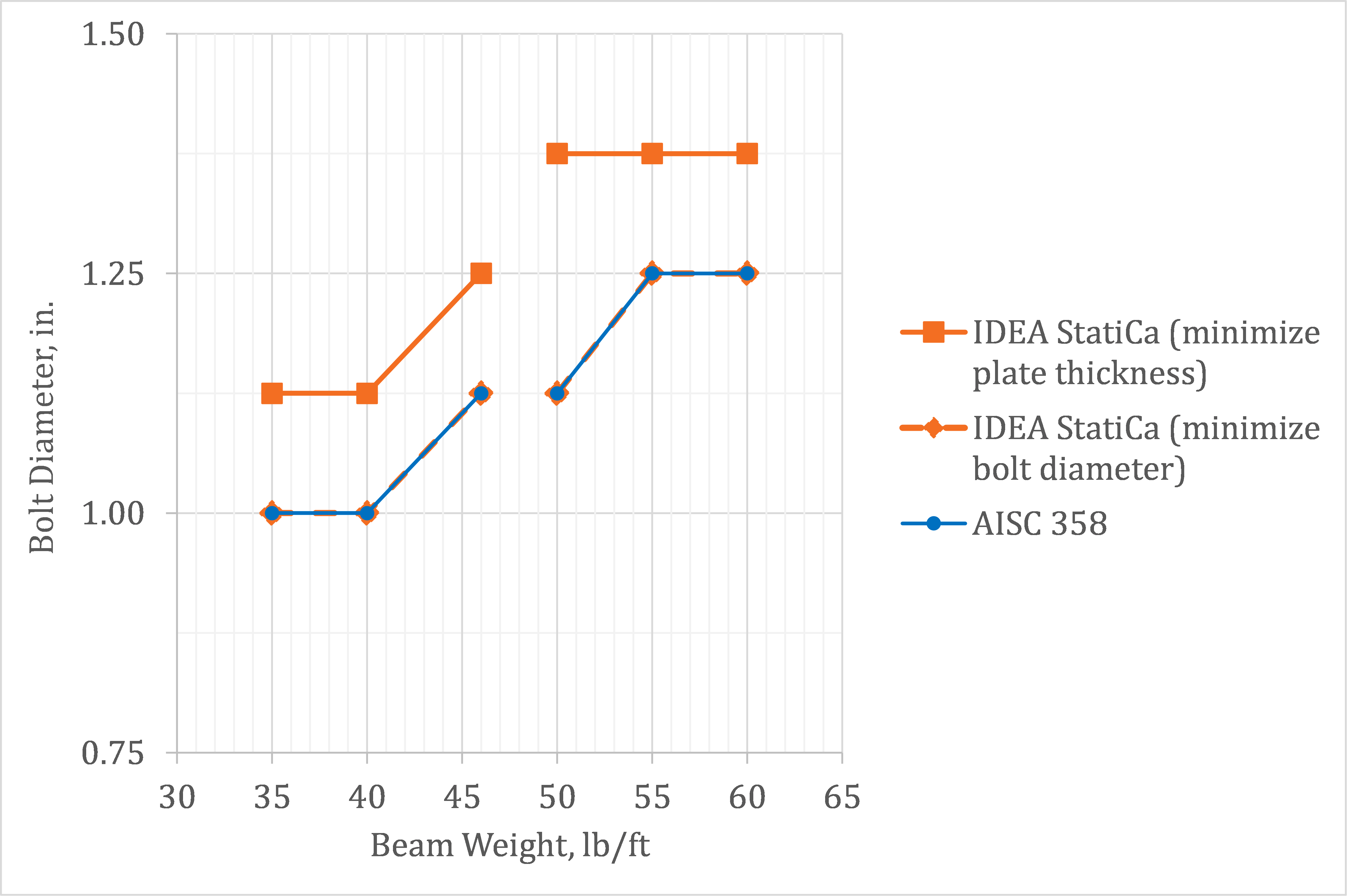
Fig. 11 Diametrul șuruburilor vs. greutatea grinzii
5 Rezumat
Acest studiu a comparat proiectarea îmbinărilor cu placă de capăt extinsă pentru momente utilizând metodele tradiționale de calcul folosite în practica din SUA și IDEA StatiCa. Observațiile cheie din studiu includ:
- IDEA StatiCa conduce la rezistențe disponibile pentru îmbinările cu placă de capăt extinsă pentru momente similare cu cele din calculele tradiționale.
- Diferențele de rezistență se datorează în principal efectului de pârghie și distribuției tensiunilor de contact, ambele fiind tratate cu ipoteze simplificate în calculele tradiționale, dar modelate explicit în IDEA StatiCa.
- Utilizând parametrii impliciți, rezistența zonei de nod a inimii din IDEA StatiCa este similară cu rezistența din AISC Specification atunci când efectul deformațiilor inelastice ale zonei de nod asupra stabilității cadrului este luat în considerare în analiză pentru determinarea rezistențelor necesare. Rezistența mai mică prevăzută în AISC Specification pentru cazul în care efectul deformațiilor inelastice ale zonei de nod asupra stabilității cadrului nu este luat în considerare în analiză pentru determinarea rezistențelor necesare poate fi obținută prin ajustarea limitei de deformație plastică în IDEA StatiCa.
- Capacitățile de proiectare prin capacitate ale IDEA StatiCa permit selectarea diametrului șuruburilor și a grosimii plăcii care sunt conservative față de procedura definită în AISC 358.
6 Referințe
AISC. (2016a). Specification for Structural Steel Buildings. American Institute of Steel Construction, Chicago, Illinois.
AISC. (2016b). Prequalified Connections for Special and Intermediate Steel Moment Frames for Seismic Applications. American Institute of Steel Construction, Chicago, Illinois.
AISC. (2017). Steel Construction Manual, 15th Edition. American Institute of Steel Construction, Chicago, Illinois.
Dowswell, B. (2011). „A Yield Line Component Method for Bolted Flange Connections." Engineering Journal, AISC, (2nd Quarter), 93–116.
Landolfo, R., D'Aniello, M., Costanzo, S., Tartaglia, R., Demonceau, J., Jaspart, J., Stratan, A., Jakab, D., Dubina, D., Elghazouli, A., și Bompa, D. (2018). Equaljoints PLUS – Volume with information brochures for 4 seismically qualified joints, European Convention for Constructional Steelwork (ECCS), Brussels, Belgium.
Murray, T. M. și Sumner, E. A. (2003). Extended End-Plate Moment Connections: Seismic and Wind Applications, Second Edition. Design Guide 4, American Institute of Steel Construction, Chicago, Illinois.