In this article, we will discuss three topics that engineers consider while designing reinforced cement concrete (RCC) structures, and how IDEA StatiCa can help with this.
Transportation loads/Construction loads
It is possible for you to design and calculate a reinforced concrete element for its intended final use; however, the element is also subjected to various load conditions during the transportation and construction phases. You can analyze the construction and service stages for reinforced concrete beams using the IDEA StatiCa Beam application. In this application, you can add stages for casting, prestressing, transportation, as well as temporary supports.
In the case of prefabricated concrete elements, engineers should consider the lifting stages during construction. The elements must be lifted by a crane to their final position as shown in the image at the top of this article. During lifting, an entirely different load situation occurs within the element. This impacts the structural element, and it must be designed to accommodate this. Furthermore, the anchoring technique of the lifting eyes, along with their placement and angle, are crucial factors to consider.
In IDEA StatiCa Detail, you can apply hanging supports and integrate the self-weight as a load effect. This way, the engineer can analyze the internal stresses and strains in the reinforced concrete element during lifting.
Let’s model the wall panel with openings in IDEA StatiCa Detail.
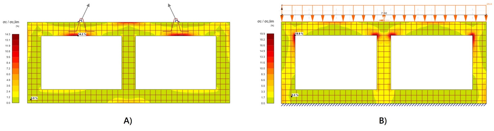
Two situations are modeled and analyzed in IDEA StatiCa Detail. Scenario A represents the load situation during lifting with two hanging supports and the self-weight applied as a load effect. Scenario B represents the end stage, where the wall is supported at the bottom and a line load is applied on the top. To analyze the differences, the ratio of compressive concrete stress and strength is visualized. You can see that the areas of compressive stresses differ significantly between the two scenarios, underscoring the importance of detailed analysis for each specific case. By utilizing reinforced concrete detailing software such as IDEA StatiCa, engineers can compare different load situations and account for them in the design and reinforcement detailing.
Additionally, the method of anchoring the lifting lugs, considering their position, angle, and type of anchor, impacts the forces and capacity of the anchorage system. Improper anchorage results in undesirable stresses in the concrete element and lifting cables, potentially leading to catastrophic consequences.
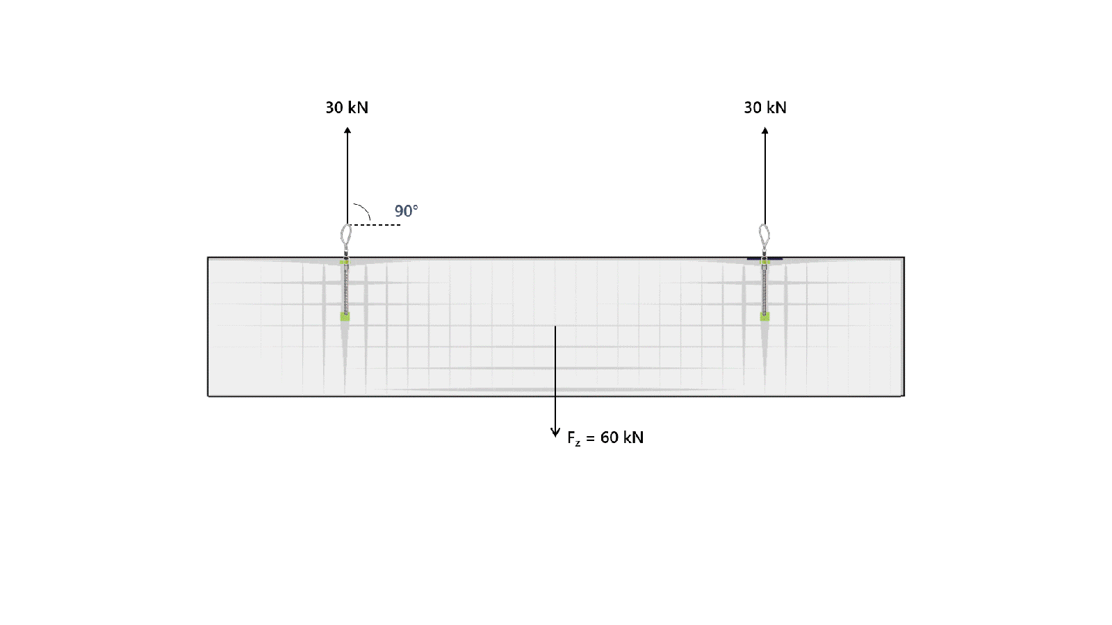
In the following example, a concrete beam with a self-weight of 60 kN is lifted by two cables. The angle of the cable changes from a perfectly vertical 90 degrees to an inclination of 30 degrees. The cables as well as the anchors in the concrete, made of straight steel rebars with perfect bonding, experience an increase in force due to this inclination. The rise in force within both the lifting cables and the beam's anchorage needs to be carefully considered when designing the lifting eyes and planning the transportation stages.
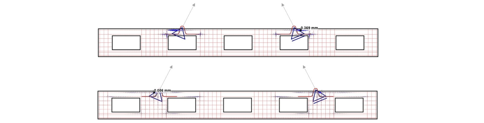
Furthermore, when lifting reinforced concrete beams that have openings, engineers should pay attention to the position of the lifting lugs. Positioning them directly above the openings induces undesired stresses and strains, leading to cracks in the concrete before the beam even begins its service life.
Foundation settlement
A building is only as strong as its foundation, which, in turn, depends on the stiffness of the soil beneath. Every site has unique soil conditions, making geotechnical investigation crucial for structural engineering. Different types of soil have varying stiffnesses and behaviors under load. Therefore, understanding the specific soil conditions and including them in the structural calculations are necessary.
Over time, foundation settlements could occur due to various reasons, but three primary factors include:
- Overestimation of soil strength and stiffness. The soil is not able to bear the applied loads.
- Poor compaction of soil, leaving air pores that vanish under compression and cause the soil to settle.
- Extreme changes in moisture content causing the soil to shrink during dry periods and swell upon saturation.
Improper design leads to undesirable settlement over time and unexpected cracks in RCC structures. The consequences range from aesthetic issues, such as uneven floors and cracked walls, to serious structural failures.
By leveraging the capabilities of advanced software like IDEA StatiCa, engineers can anticipate potential problems. IDEA StatiCa Detail enables the modeling of line supports with specific stiffness to simulate the real behavior of soils accurately. This is particularly useful when, for example, a concrete wall is situated on two different foundations or soil types, allowing engineers to analyze the effects of soil stiffness on the concrete structure's behavior. As demonstrated below, larger stresses and strains emerge in scenario B, where the right part of the support has a lower stiffness k2, representing a weaker soil type.
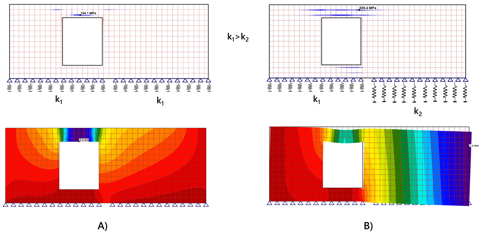
The analysis reveals additional cracks forming above the opening. The concrete should be further reinforced to bear these additional stresses. Alternatively, you could enhance the soil conditions or the design of the foundation, making it stiffer, meaning fewer settlements will occur. By checking this phenomenon using advanced software, many issues can be prevented in the future. In the end, it saves time, money, effort, and prevents potential unsafety.
Reinforcement detailing
The detailing of steel reinforcement in concrete structures requires both theoretical and practical knowledge. What appears to be the best solution in terms of moment capacity might not always be the most practical solution. To demonstrate, let's examine a concrete frame joint as shown below. The resistance of a RCC framed structure critically relies on the reinforcement detailing, which is essential for achieving the required load capacity and ensuring ductile behavior.
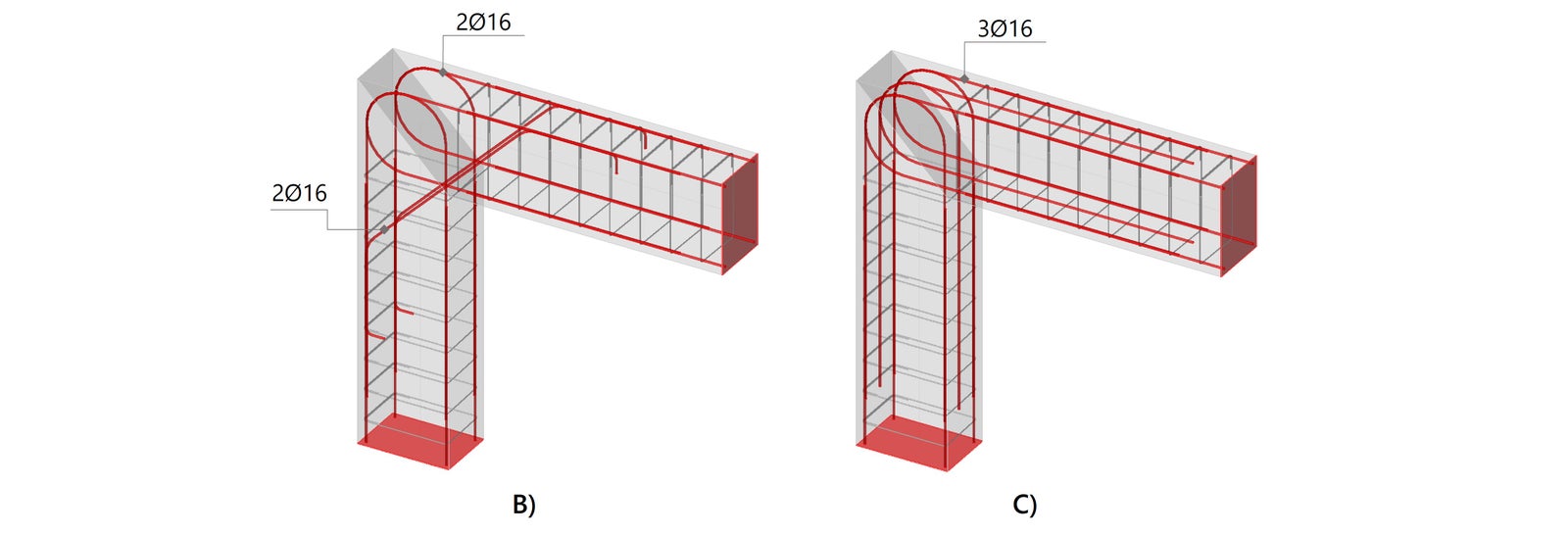
IDEA StatiCa Detail lets you accurately model reinforcement layouts and view them in 3D. This gives engineers a better understanding of the rebar positions and possible clashes. Moreover, using the Detail application, the engineer is able to model and analyze different configurations, which makes them more flexible in proposing several designs and choosing the best one based on technical and practical needs.
We can model the concrete frame joint in IDEA StatiCa Detail as shown below. The models are simplified for clarification. Based on the dimensions and applied loads, the engineer has to design the reinforcement inside the concrete corner. It can be argued that option A is often used in frame corners experiencing closing moments. Furthermore, in frame corners subjected to opening moments, inclined bars are commonly included, as demonstrated in option B.
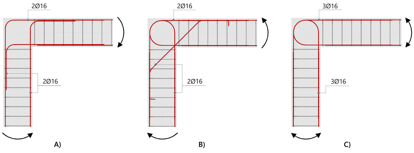
The reality of engineering is often more complex – designs may need adjustments to resist both opening and closing moments, or to meet practical requirements on site. For a better explanation, consider a hypothetical scenario where the constructor prefers to avoid inclined bars in option B for practical reasons on site. Using IDEA StatiCa, the engineer is equipped to analyze alternatives and can find, for example, that the influence of inclined bars seems to be less effective than initially thought. It might be sufficient to simply add an extra reinforcement loop. Consequently, three reinforcement loops, as illustrated in option C, prove to be adequate for bearing the applied loads.
These engineering considerations can be thoroughly explored with advanced concrete design software like IDEA StatiCa, which allows for the analysis of various configurations to determine the optimal solution for your design.
Avoid inaccurate estimates and be sure with IDEA StatiCa!
Start your trial today and enjoy 14 days of full access and services free of charge.
Start free trial