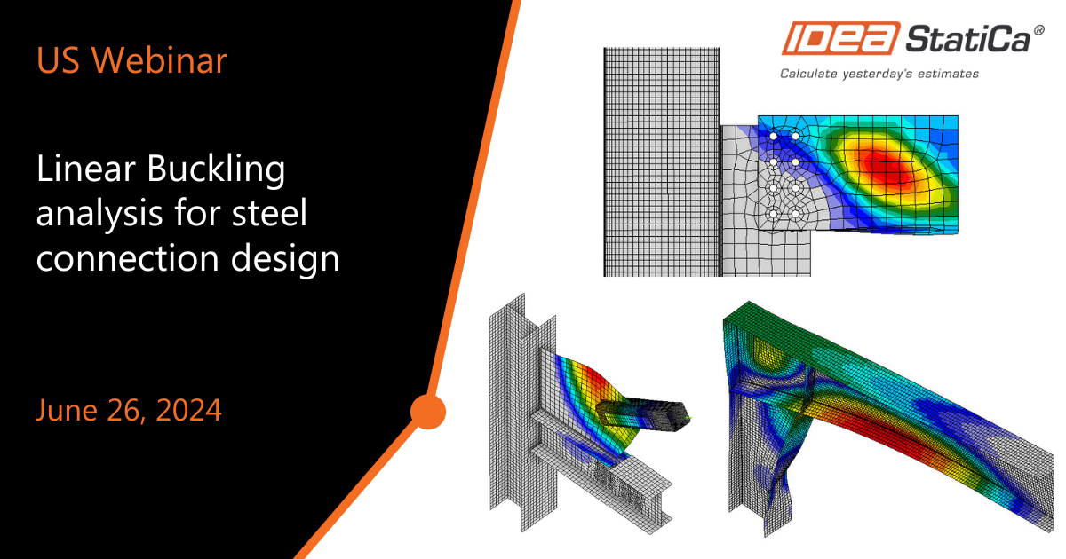
Linear Buckling analysis for steel connection design
-
2024-06-26T16:00:00.0000000Z(in your local time, 24-hour format)
Webinar date:
Join the webinar and learn about
- Linear buckling analysis in IDEA StatiCa
- Identify the buckling issue
- Learn the recommended limit factors
- See common examples
Speakers

IDEA StatiCa US

IDEA StatiCa US

IDEA StatiCa US
During this webinar, we will use IDEA StatiCa connection models to explain how to use the linear buckling analysis during your design process.
The Buckling load factors and their associated buckling mode shapes are derived from linear buckling analysis (sometimes called Eigenvalue Buckling or Euler Buckling analyses). This analysis is mathematically similar to a modal analysis. However, it does not give stresses or displacements. The buckling modes indicate the shape of the structure when it buckles because buckling is a state of collapse, not a deformation.
From the linear buckling analysis results, we will help you identify where the buckling is predicted and how serious it is.
The designer needs engineering judgment, and IDEA StatiCa provides numerical results to let the user make informed design decisions.
The participants who attend the live webinar will receive a certificate of attendance.
Presentation slides
Find the webinar video at the end of the webinar summary.
Buckling limit states for Connection design in AISC
The traditional design method uses mathematical equations to calculate the strength of structural elements and systems. Although accurate equations have been developed for most common conditions, only empirical or semi-empirical equations are available for some connection elements. Design guidance is unavailable for many situations encountered in design practice. In these cases, simplified models are typically used to characterize the behavior of connection elements.
The J4 of the AISC building specification and the AISC manual Chapter 9 provide formulae for designing plates and elements part of the connections.
In the J4 chapter of AISC 360, the plates are classified by the slenderness ratio, which we will discuss later in this webinar.
Linear buckling analysis in IDEA StatiCa
IDEA StatiCa Connection can perform linear buckling analysis of a model of a joint. The results are predicted in buckling modes. The critical load at which buckling of the perfect model occurs is calculated for each buckling mode. Critical load is presented by multipliers of the load acting on the joint. The user can determine the safe buckling design according to the buckling mode and critical load multiplier.
Buckling mode shapes
The buckling mode shapes show the results of eigenvalue linear elastic analysis. These are normalized vectors so that the maximum displacement has a magnitude of 1 and does not represent actual magnitudes of deformation at critical loads. They show the predicted buckle shape of the eigenmode and the critical point, and from there, you determine if that is a global or local issue in your connection.
By default, we show six buckling mode shapes, but you can calculate more by setting the value in the Code setup. To see more shapes, click on the shapes in the table.
Global or local buckling?
First, it is necessary to identify the type of buckling on the plates to assess whether your connection will fail. There are two main categories: global and local.
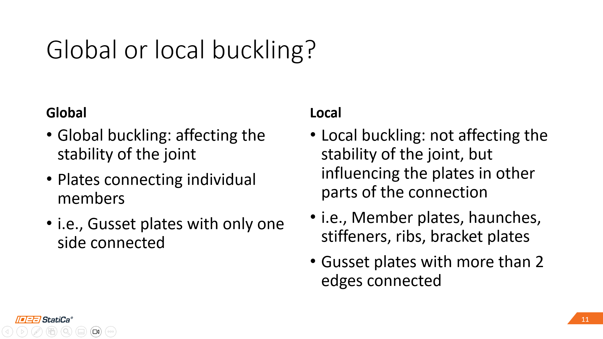
The category selection depends on where the red spot is in the different mode shapes; the first mode shape is always the most critical.
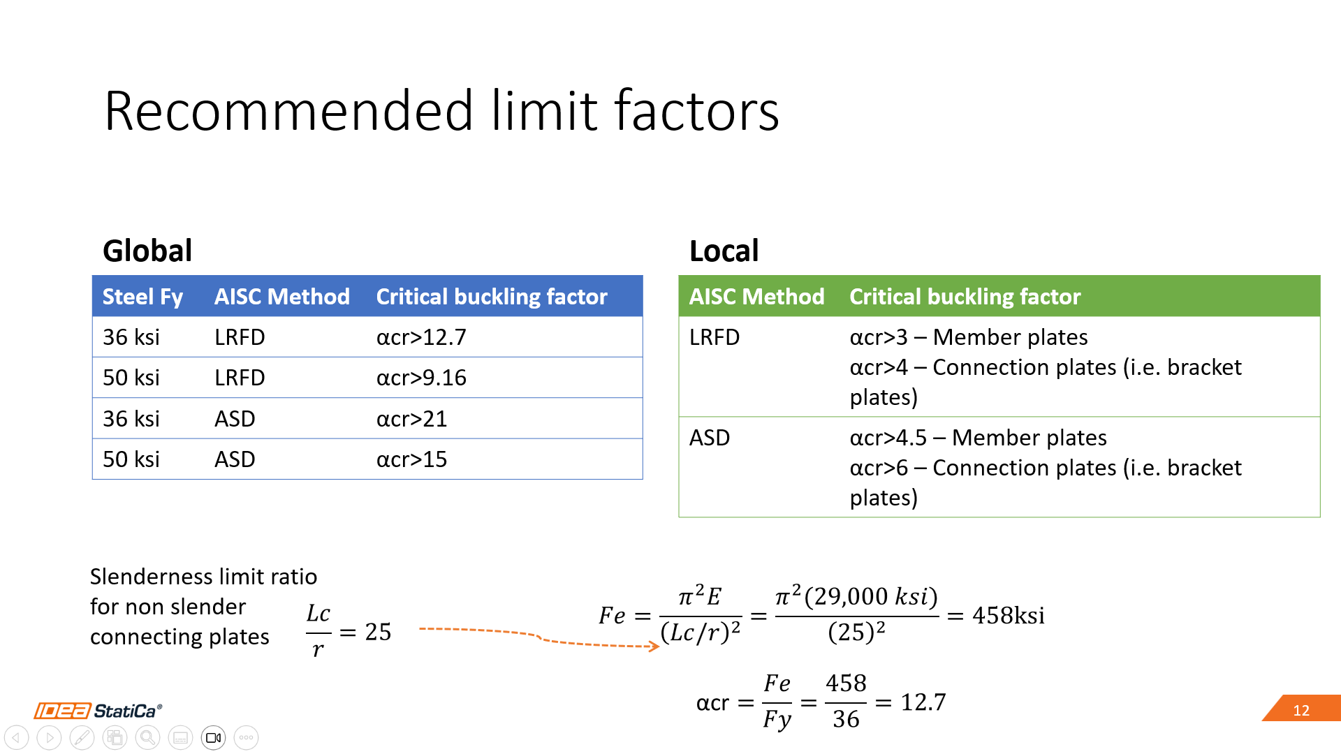
Recommended buckling limit factors
We have defined limit factors to help the users make design decisions using IDEA StatiCa linear buckling analysis. We took the AISC limit state from J4, used the limit slenderness ratio, and, from there, got the critical buckling limit factors. With that slenderness ratio, we avoid cases where inelastic buckling could control.
The slenderness ratio equals 25, so we use that on the elastic critical stress formula. We get a value of 458 ksi. For the A36 Steel, the ratio gives us a limit factor of 12.7. That is how the global limit factors were determined.
We use the limiting width-to-thickness ratio λr from AISC 360, Table B4.1a for the member local factors. Bo Doswell collaborated with us to evaluate connecting bracket plates. This research aimed to develop practical design guidelines for the buckling strength of bracket plates that can be implemented with LBA.
A critical buckling load ratio limit of 3 has been evaluated for bearing stiffeners (report coming soon), coped beams, and beam-over-column connections.
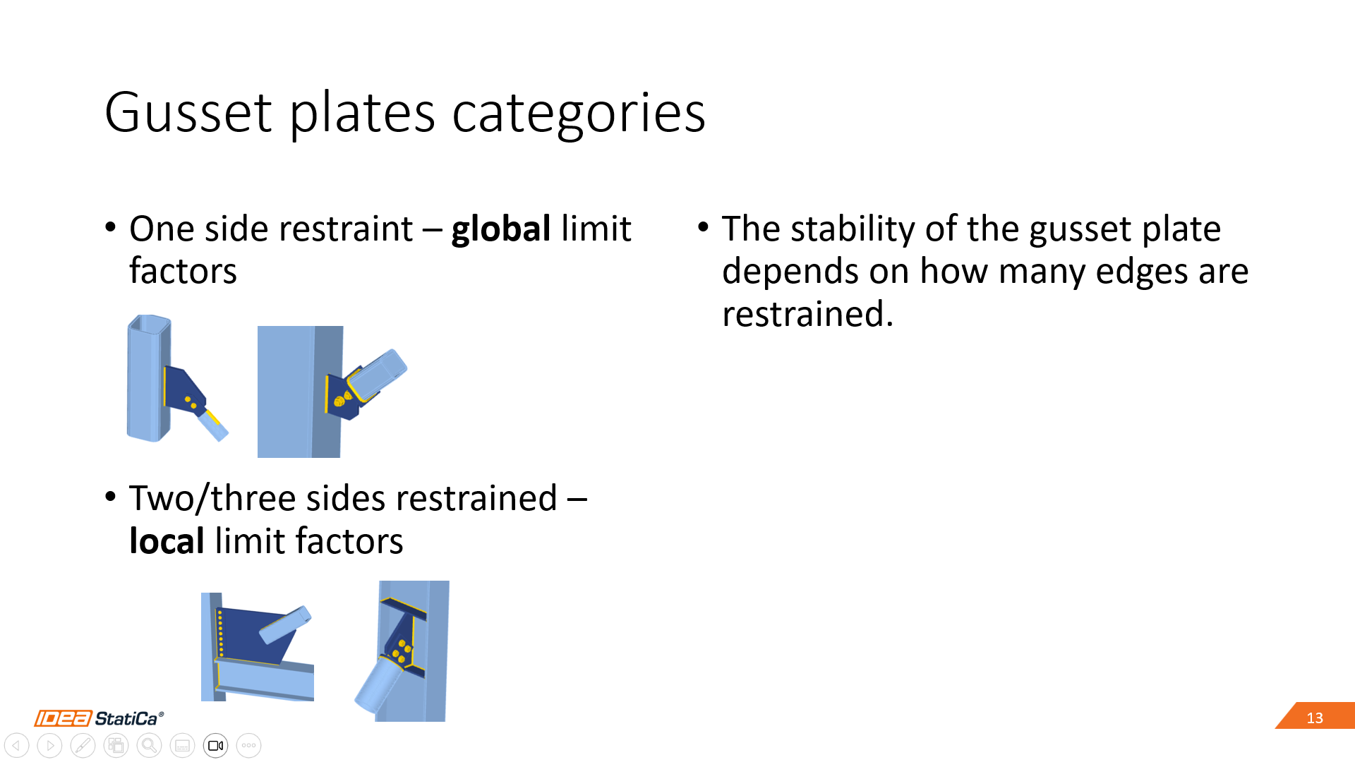
Gusset plates have been identified in the global buckling category; however, their stability depends on how many edges are restrained.
The design process in IDEA StatiCa, including Buckling analysis
- Design the connection: Run regular stress/strain analysis and verify you comply with all the code checks
- Run Buckling analysis: Go to Check tab>Calculate>Buckling
- Analyze results and decide: Review the mode shapes and buckling load factors. Compare against recommended factors. Higher than recommended factor? Design is OK
- Re-iterate until Buckling is OK: Use your engineering judgment to decide the solution if the connecting elements are under the recommended factors.
What to do if the buckling factor is below the recommended limit factors?
- Use your engineering judgment!
- If it is a global buckling issue (buckling happening in one of the connecting elements), stiffen the connection.
- If it is a local member plates issue, review the member design (IDEA StatiCa member app)
- Local buckling in thin-walled/hollow section members, a non-linear buckling analysis is probably required (IDEA StatiCa member app)
Sample Models
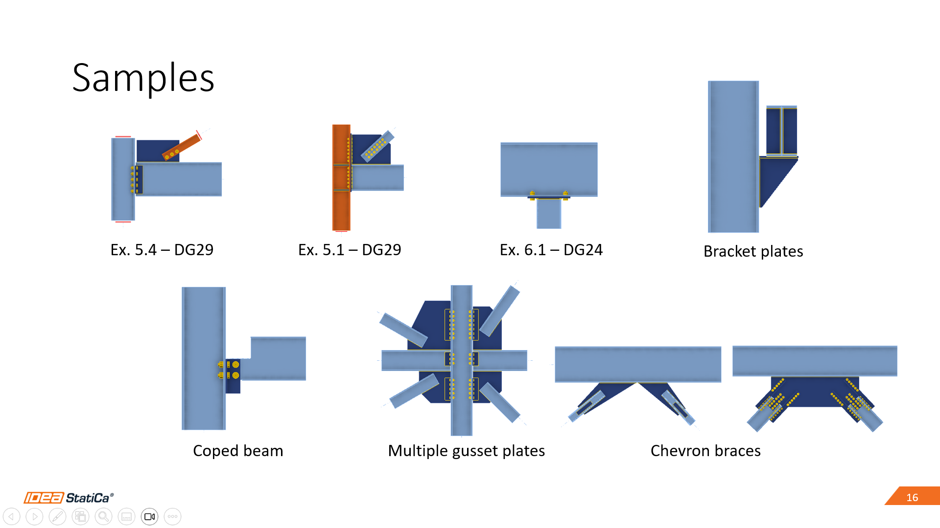
See the following picture to see the first mode of each joint:
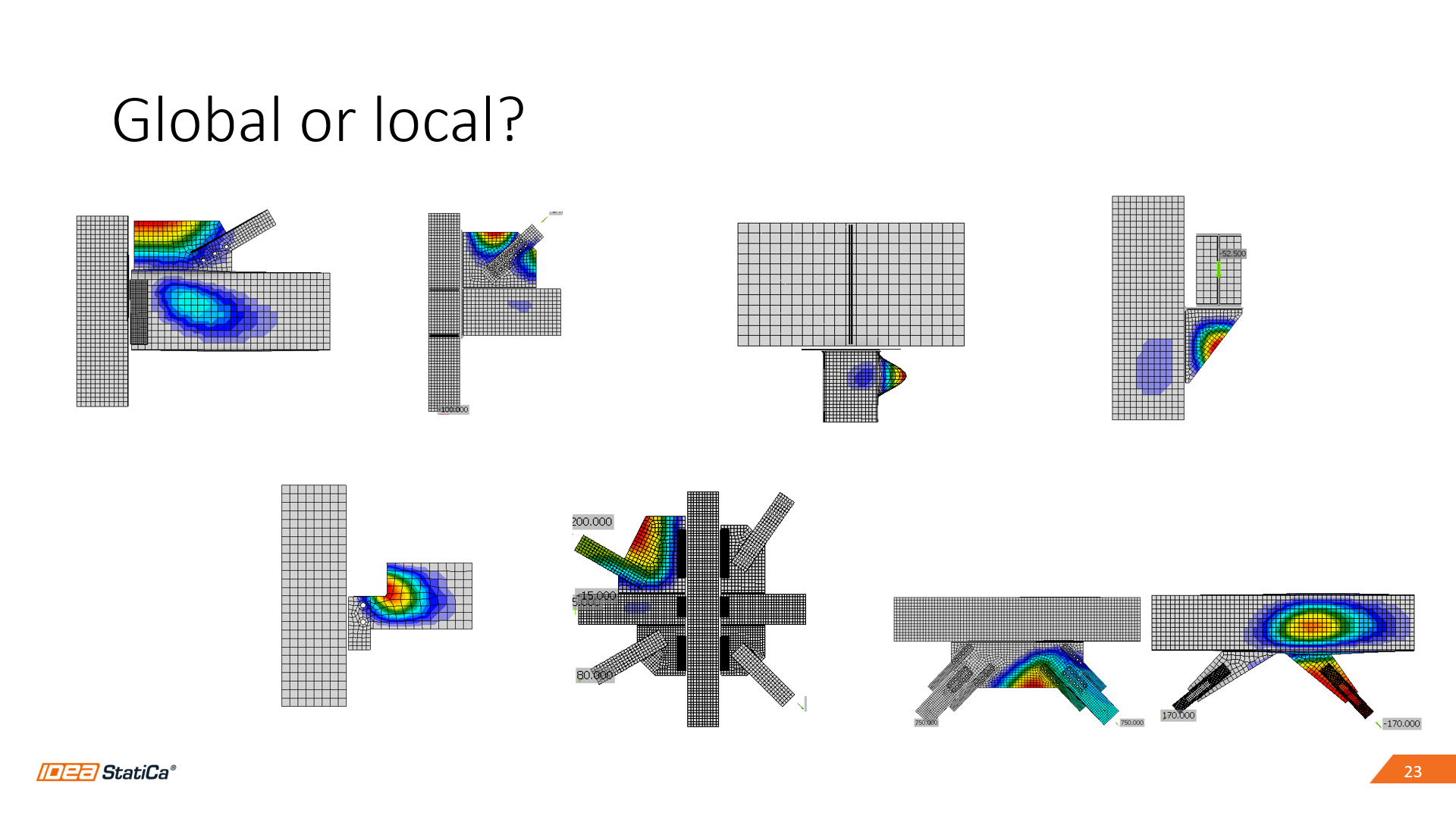
Depending on where the critical buckling shape is, the selection of the recommended buckling limit factors:

Summary
- IDEA StatiCa connection uses linear buckling analysis to provide a buckling factor only and recommended limit factors are provided
- The recommended limit factors ensure the non-slender design of connection plates
- Buckling analysis in IDEA StatiCa is a tool
- It doesn’t provide a pass/fail result
- Use your engineering judgment and experience to decide the design solution
- Before running the analysis, make sure the loads and the connection design are OK