Idea Statica
  • Steel
  • Concrete
  • BIM & workflows
  • Support & Learning
  • Pricing
  • Company
  • Steel overview
  • Connection design
  • Member design
  • Parametric design
  • Steel case studies
  • Concrete overview
  • Walls and D-regions
  • Anchoring design
  • Members & cross-sections
  • Concrete case studies
  • BIM overview
  • Supported integrations
  • Checkbot
  • Viewer
  • APIs
  • Support Center
  • E-learning & certification
  • Blog
  • Downloads & Licensing
  • Plans
  • Free community tool
  • Enterprise customers
  • Students & educators
  • How much will you save?
  • About us
  • Contact
  • Research & development
  • Authorized resellers
  • Meet our customers
  • Career
  • Steel
    Steel overviewConnection designMember designParametric designSteel case studies
  • Concrete
    Concrete overviewWalls and D-regionsAnchoring designMembers & cross-sectionsConcrete case studies
  • BIM & workflows
    BIM overviewSupported integrationsCheckbotViewerAPIs
  • Support & Learning
    Support CenterE-learning & certificationBlogDownloads & Licensing
  • Pricing
    PlansFree community toolEnterprise customersStudents & educatorsHow much will you save?
  • Company
    About usContactResearch & developmentAuthorized resellersMeet our customersCareer
14-Day Trial
14-Day Trial
  • Steel
  • Concrete
  • BIM & workflows
  • Support & Learning
  • Pricing
  • Company

Subscribe to our newsletter

Company

  • About us
  • Partners
  • Careers
  • Patent

Resources

  • Customer projects
  • Case studies
  • Connection Library
  • Verification books

Legal

  • EULA
  • Privacy policy
  • California Privacy
  • TOS Viewer
  • Licensing

Help

  • Contact
  • Quote request
  • Resellers
  • Downloads
FacebookInstagramLinkedInYouTube

© IDEA StatiCa 2009-2026

Trusted and used worldwide by engineers, fabricators & consultants.

Support CenterKnowledge Base ArticlesWhat is the singularity warning?
Advanced analysis types for your steel structures
Nonconformity in connection analysis results
Connection analysis 0% or doesn't reach 100%
What is the singularity warning?
Stop at limit strain
Torsion moments and warping
Warping of members – Load in shear center
Thin-walled (cold-formed) members
Load effects displayed in the scene
2nd generation of Eurocode 3 in Steel apps
IDEA StatiCa Member for steel
Why is 5% plastic strain limit used in material diagram for EN?
Member analysis - Interpretation of MNA and GMNIA results
How to input imperfections in Member
Singularity detection in Member
What is the singularity warning?
3D visualization of deformations
Smooth results with precise meshing
What is the singularity warning?
SteelConnection designKnowledge baseConnectionModeling

What is the singularity warning?

This article is also available in
ENCZDEESFRITPTNLHUROKRPLTHTRVIZH

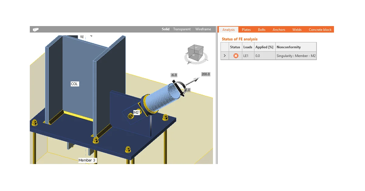
A singularity warning informs the user that the analysis stopped due to mathematical nonconformity, which happens when a part of the model is free to move or spin infinitely as a mechanism without any resistance. This article describes the most common reasons behind singularities in IDEA StatiCa Connection analysis.

Usually, in case of singularity in IDEA StatiCa Connection analysis, the description of singularities can be found in the Check screen in the Analysis tab. Also, the cause of the singularity is usually possible to see on the 3D screen.
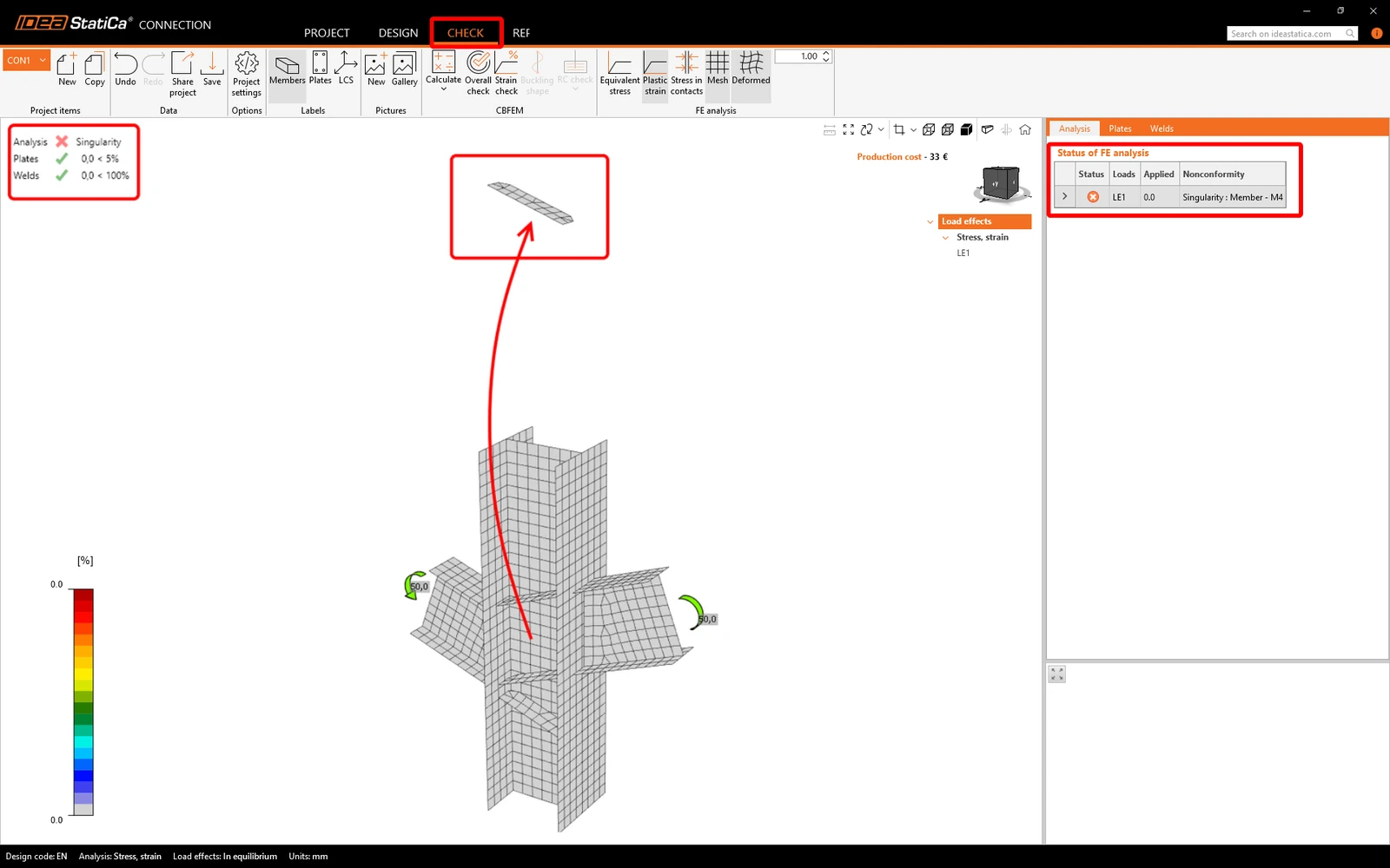
The singularity can be caused by the following: 

  • Unconnected Member or Plate
  • Singularity on circular hollow sections (CHS)
  • Single-bolt connection subjected to bending moment
  • Too wide gap between connected plates

Unconnected Member or Plate

The simpliest reason for singularity is when one or more components are not connected with to the rest of the structure (missing welds, bolts, or contact operations). The finite elements of this component are not supported anyhow and thus "flies" away.

Singularity on circular hollow sections (CHS)

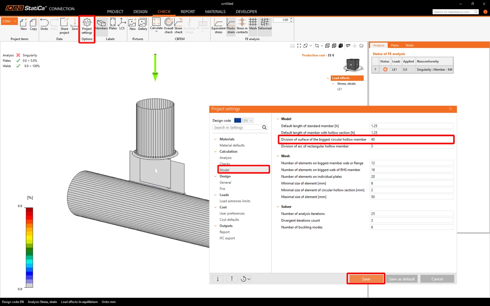
In IDEA StatiCa Connection, Circular Hollow Section (CHS) members are modeled using plane shell elements. Cutting a CHS or tubular section along its axis with a plate can cause an analysis singularity. A similar singularity warning often occurs when welding a tube along its length. Both issues are driven by the same cause: discretizing a curved surface into flat angular shell elements may create geometric mismatches at the cut or weld line.

To resolve this error, open the Project settings and change the default value of the Division of surface of the biggest circular hollow member from 64 to some lower number, e.g., 40.
Single-bolt connection subjected to bending moment

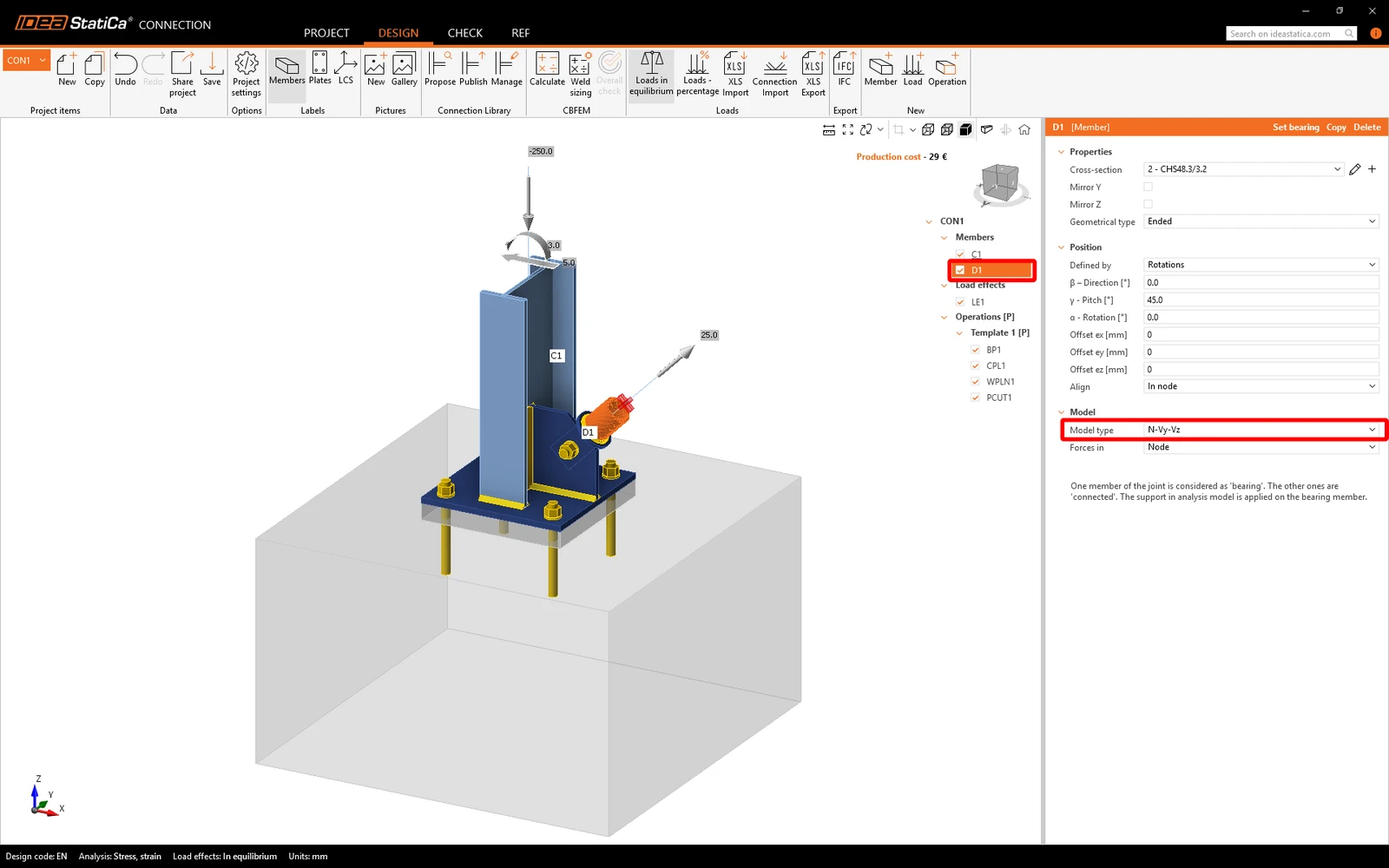
Applying a moment to a member connected by a single-bolt transforms the joint from a stable connection into a kinematic mechanism, causing an analysis singularity. To prevent this, change the Model type of the connected member to N-Vy-Vz, which restricts moment transfer and ensures the single-bolt joint carries only shear and normal forces.
Too wide gap between connected plates

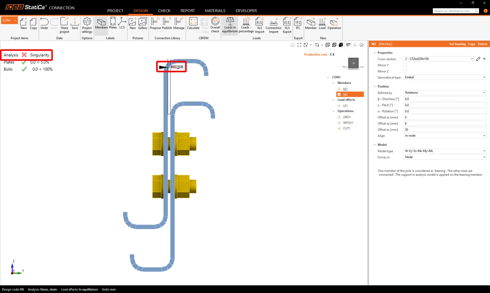
When modeling a contact or bolted connection between plates, pay attention to the gap distance between them. The operation Bolt grid and Contact  can bridge small offsets between items , however, the maximum allowable gap distance is 2 mm. If the gap exceeds 2 mm, the calculation cannot be executed and the analysis will result in singularity.
See also the videos explaining the singularities and how to resolve them.

Want to improve your skills? Visit our Campus

Learn how to use IDEA StatiCa effectively with our self-paced e-learning courses

Start learning
Related articles

Connection analysis 0% or doesn't reach 100%
  • Steel
  • Connection
  • EN (Eurocode)
  • Overall check
  • Project settings
  • GMNA
  • AISC (USA)
  • v25.1
  • +8
  • Steel
  • Connection
  • EN (Eurocode)
  • Overall check
  • Project settings
  • GMNA
  • AISC (USA)
  • v25.1

Knowledge base

Connection analysis 0% or doesn't reach 100%

Read more
The finite element analysis might not converge due to some element that is not sufficiently supported and can freely move or rotate. Analysis of the structural design of complex welded and bolted steel connections.
  • Steel
  • Connection
  • AISC (USA)
  • AS (Australia)
  • CSA (Canada)
  • EN (Eurocode)
  • IS (India)
  • GB (China)
  • HKG (Hong Kong)
  • CBFEM
  • SP 16 (Russia)
  • +11
  • Steel
  • Connection
  • AISC (USA)
  • AS (Australia)
  • CSA (Canada)
  • EN (Eurocode)
  • IS (India)
  • GB (China)
  • HKG (Hong Kong)
  • CBFEM
  • SP 16 (Russia)

Knowledge base

Analysis convergence of complex steel connection models

Read more
Mesh generation error for a plate imported from DXF
  • Steel
  • Connection
  • Bolts
  • Modeling
  • Plates
  • +5
  • Steel
  • Connection
  • Bolts
  • Modeling
  • Plates

Knowledge base

Mesh generation error for a plate imported from DXF

Read more
Stress in plates higher than the yield strength
  • Steel
  • Connection
  • Overall check
  • CBFEM
  • Stress/strain
  • +5
  • Steel
  • Connection
  • Overall check
  • CBFEM
  • Stress/strain

Knowledge base

Stress in plates higher than the yield strength

Read more