Idea Statica
  • Steel
  • Concrete
  • BIM & Workflows
  • Support & Learning
  • Pricing
  • Company
  • Steel overview
  • Connection design
  • Member design
  • Parametric design
  • Steel case studies
  • Concrete overview
  • Walls and D-regions
  • Anchoring design
  • Concrete case studies
  • BIM Overview
  • Supported integrations
  • Checkbot
  • Viewer
  • APIs
  • Support Center
  • E-learning & certification
  • Blog
  • Downloads & Licensing
  • Plans
  • Free community tool
  • Enterprise customers
  • Students & educators
  • How much will you save?
  • About us
  • Contact
  • Research & development
  • Authorized resellers
  • Meet our customers
  • Career
  • Steel
    Steel overviewConnection designMember designParametric designSteel case studies
  • Concrete
    Concrete overviewWalls and D-regionsAnchoring designConcrete case studies
  • BIM & Workflows
    BIM OverviewSupported integrationsCheckbotViewerAPIs
  • Support & Learning
    Support CenterE-learning & certificationBlogDownloads & Licensing
  • Pricing
    PlansFree community toolEnterprise customersStudents & educatorsHow much will you save?
  • Company
    About usContactResearch & developmentAuthorized resellersMeet our customersCareer
14-Day Trial
14-Day Trial

Subscribe to our newsletter

Company

  • About us
  • Partners
  • Careers
  • Patent

Resources

  • Customer projects
  • Case studies
  • Connection Library
  • Verification books

Legal

  • EULA
  • Global privacy policy
  • California Privacy
  • TOS Viewer
  • Licensing

Help

  • Contact
  • Quote request
  • Resellers
  • Downloads
FacebookInstagramLinkedInYouTube

© IDEA StatiCa 2009-2026

Trusted and used worldwide by engineers, fabricators & consultants.

Support CenterKnowledge Base ArticlesCode-check of bolts and preloaded bolts (AISC)
Advanced analysis types for your steel structures
Bolts are too close to plate edge
Traffic lights for forces in bolts
Prying and high tension force in bolts
Bolt force distribution in end-plate beam-to-column connection
Bolt shear force calculated per shear plane
Through-bolts in hollow sections: design them as pins, not bolts
Bolt bearing distances for Eurocode
Warnings for welds and bolts connecting the same plates
Slip resistance check update according to SP 16
Detailing improvements for bolts and welds in Eurocode
Angle to the grain of the steel-to-timber connections
Filler plate (packing plate) recognition
Smooth results with precise meshing
Code-check of bolts and preloaded bolts (EN)
Code-check of bolts and preloaded bolts (AISC)
Code-check of bolts and preloaded bolts according to Canadian standards
Code-check of bolts and preloaded bolts according to Australian standards
Code-check of bolts and preloaded bolts according to Chinese standard
Code-check of bolts according to Hong Kong Code
Code-check of bolts and preloaded bolts according to Hong Kong Code
Code-check of bolts according to Indian standard
Code-check of preloaded bolts according to Indian standards
Code-check of bolts and preloaded bolts according to Russian standards
The forces in bolts are determined by finite element analysis. The tensile forces include prying forces. The bolt resistances are checked according to AISC 360 - Chapter J3. Structural design of bolted steel connections.
SteelKnowledge baseConnectionCBFEMBolts

Code-check of bolts and preloaded bolts (AISC)

This article is also available in
ENCZDEESFRITPTNLHUROKRPLTHTRVIZH

The forces in bolts are determined by finite element analysis. The tensile forces include prying forces. The bolt resistances are checked according to AISC 360 - Chapter J3.

Bolts

Tensile and shear strength of bolts

The design tensile or shear strength, ϕRn, and the allowable tensile or shear strength, Rn/Ω of a snug-tightened bolt is determined according to the limit states of tension rupture and shear rupture as follows:

Rn = FnAb

ϕ = 0.75    (LRFD, editable in Code setup)

Ω = 2.00    (ASD, editable in Code setup)

where:

Ab – nominal unthreaded body area of bolt or threaded part

Fn – nominal tensile stress, Fnt, or shear stress, Fnv, from Table J3.2

The required tensile strength includes any tension resulting from prying action produced by the deformation of the connected parts.

Combined Tension and shear in bearing type connection

The available tensile strength of a bolt subjected to combined tension and shear is determined according to the limit states of tension and shear rupture as follows:

Rn = F'nt Ab    (AISC 360-16 J3-2)

ϕ = 0.75    (LRFD, editable in Code setup)

Ω = 2.00    (ASD, editable in Code setup)

Fnt′=1.3Fnt−frvFntϕFnvF'_{nt}=1.3 F_{nt} - \frac{f_{rv} F_{nt}}{\phi F_{nv}}Fnt′​=1.3Fnt​−ϕFnv​frv​Fnt​​   (AISC 360-16 J3-3a LRFD)

Fnt′=1.3Fnt−frvΩFntFnvF'_{nt}=1.3 F_{nt} - \frac{f_{rv} \Omega F_{nt}}{F_{nv}}Fnt′​=1.3Fnt​−Fnv​frv​ΩFnt​​    (AISC 360-16 J3-3b ASD)

where:

  • F'nt – nominal tensile stress modified to include the effects of shear stress
  • Fnt – nominal tensile stress from AISC 360-16 Table J3.2
  • Fnv – nominal shear stress from AISC 360-16 Table J3.2
  • frv – required shear stress using LRFD or ASD load combinations. The available shear stress of the fastener shall be equal or exceed the required shear stress, frv

Bearing strength in bolt holes

The available bearing strengths, ϕRn and Rn/Ω, at bolt holes are determined for the limit state of bearing as follows:

ϕ = 0.75    (LRFD, editable in Code setup)

Ω = 2.00    (ASD, editable in Code setup)

The nominal bearing strength of the connected material, Rn, is determined as follows:

For a bolt in a connection with standard holes:

Rn = 1.2 lc t Fu ≤ 2.4 d t Fu    (AISC 360-16 J3-6a, J3-6a, c)

For a bolt in a connection with slotted holes:

Rn = 1.0 lc t Fu ≤ 2.0 d t Fu    (AISC 360-16 J3-6a, J3-6e, f)

where:

  • Fu – specified minimum tensile strength of the connected material
  • d – nominal bolt diameter
  • lc – clear distance, in the direction of the force, between the edge of the hole and the edge of the adjacent hole or edge of the material
  • t – thickness of the connected material

Preloaded bolts

The design slip resistance of preloaded class A325 or A490 bolt with the effect of tensile force Ft

Preloading force to be used AISC 360-10 tab. J3.1.

Tb = 0.7 fub As

Design slip resistance per bolt AISC 360-10 par. J3.8

Rn = kSC μ Du hf Tb ns

Utilization in shear [%]:

Uts = V / ϕRn    (LRFD)

Uts = Ω V / Rn    (ASD)

where:

  • As – tensile stress area of the bolt
  • fub – ultimate tensile strength
  • kSC=1−FtDuTbnbk_{SC}=1-\frac{F_t}{D_u T_b n_b}kSC​=1−Du​Tb​nb​Ft​​   – factor for combined tension and shear (LRFD) (J3-5a)
  • kSC=1−1.5FtDuTbnbk_{SC}=1-\frac{1.5 F_t}{D_u T_b n_b}kSC​=1−Du​Tb​nb​1.5Ft​​     – factor for combined tension and shear (ASD) (J3-5b)
  • μ – mean slip factor coefficient editable in Code setup
  • Du = 1.13 – multiplier that reflects the ratio of the mean installed bolt pretension to the specified minimum bolt pretension
  • hf = 1.0 – factor for fillers
  • ns – number of the friction surfaces; Check is calculated for each friction surface separately
  • V – shear force acting on the bolt
  • ϕ = 1.0 – resistance factor for standard size holes (LRFD) editable in Code setup
  • ϕ = 0.7 – resistance factor for slotted holes (LRFD)
  • Ω = 1.5 – resistance factor for standard size holes (ASD) editable in Code setup
  • Ω = 2.14 – resistance factor for slotted holes (ASD)
Related articles

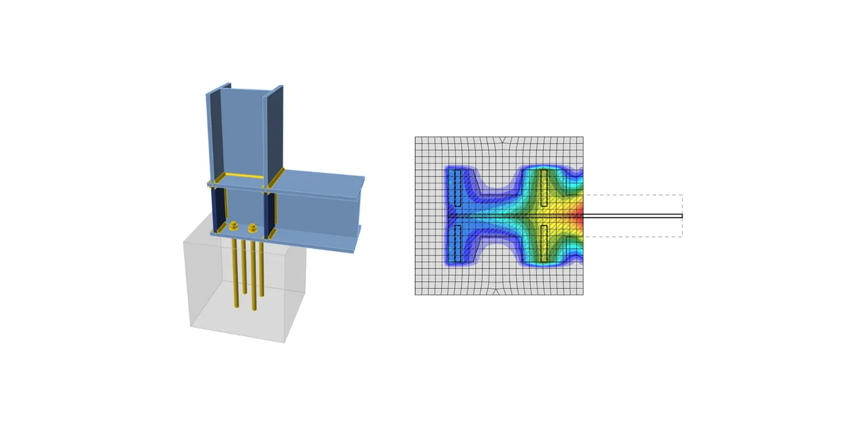
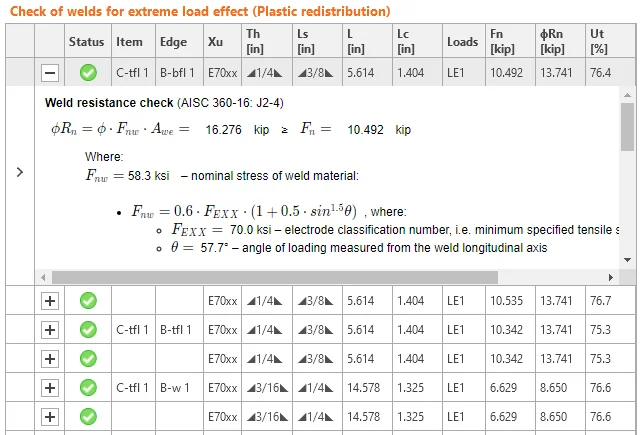
Fillet welds are checked according to AISC 360 - Chapter J2. The strength of CJP groove welds is assumed the same as the base metal and is not checked. IDEA StatiCa - structural engineering design software for modeling welded connections.
  • Steel
  • Connection
  • CBFEM
  • Welds
  • AISC (USA)
  • +5
  • Steel
  • Connection
  • CBFEM
  • Welds
  • AISC (USA)

Knowledge base

Code-check of welds (AISC)

Read more
Code-check of concrete blocks (AISC)
  • Steel
  • Connection
  • Anchoring
  • CBFEM
  • Concrete block
  • Steel-to-concrete
  • AISC (USA)
  • +7
  • Steel
  • Connection
  • Anchoring
  • CBFEM
  • Concrete block
  • Steel-to-concrete
  • AISC (USA)

Knowledge base

Code-check of concrete blocks (AISC)

Read more
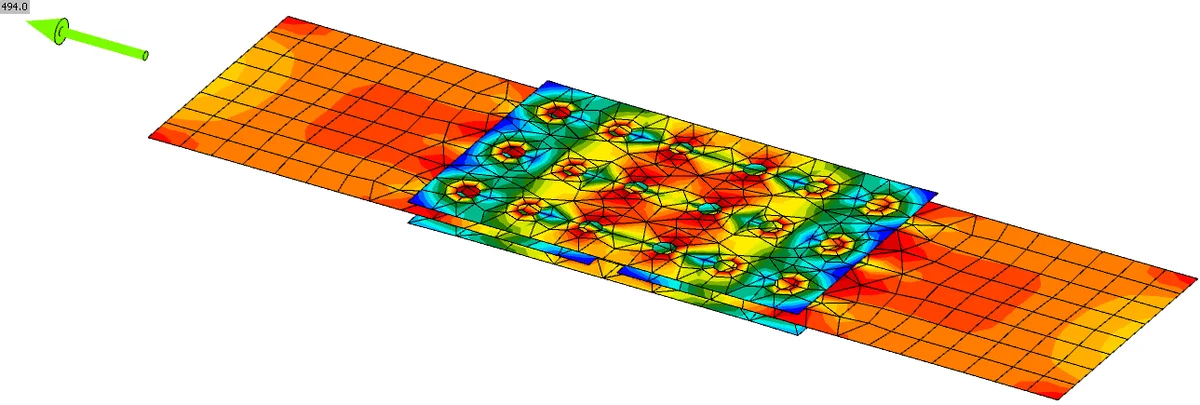
Bolted splice connection (AISC)
  • Steel
  • AISC (USA)
  • CBFEM
  • Bolts
  • Connection
  • +5
  • Steel
  • AISC (USA)
  • CBFEM
  • Bolts
  • Connection

Verifications

Bolted splice connection (AISC)

Read more
Workflows for preloaded bolts
  • Steel
  • SLS
  • Connection
  • Bolts
  • +4
  • Steel
  • SLS
  • Connection
  • Bolts

Webinar

Summer Series - Workflows for preloaded bolts

Read more