
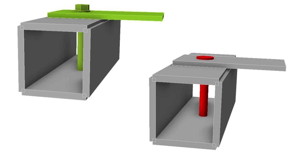


A benchmark in IDEA StatiCa Connection shows the consequence: the same M16 8.8 bolt passes the standard bolt check but fails when modeled as a pin. Here is why, and how to design through-bolts correctly.
IDEA StatiCa Connection can model and analyze nearly any joint geometry. Some connections, however, are non-standard: the general bolt checks provided by the implemented codes do not accurately describe their behavior. A typical example is a hollow section, usually an RHS or SHS, connected with through-bolts. These are long bolts or threaded rods that pass through both walls of the section, with the head and nut bearing on the outer faces.
Through-bolts are an alternative to blind bolts, Hollo-Bolts, flow-drilled bolts and other special one-sided fasteners. They are easy to source: a threaded rod, nuts and washers are all that is needed. Their mechanics, however, differ from a conventional bolted joint in three ways.
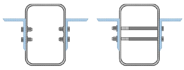
Fig. 1 Connections to an HSS wall: bolts in a single wall (left) and through-bolts passing through both walls (right). Source: J. McCormick, Steel Tube Institute (2017)
Key takeaways
- An unsleeved through-bolt should be modeled as a pin in the model, rather than being classified as a bolt.
- Non-prestressed bolts with a tight internal sleeve can be modeled as standard bolts if the sleeve prevents bending.
- If the sleeve doesn't adhere to the bolts and clearance is intended, model bolts as pins.
- It is important to note that friction bolts are prohibited for this type of connection within IDEA StatiCa Connection.
Three ways a through-bolt differs from a bolt
1. The bolt cannot be preloaded in an unreinforced hollow section
Tightening the bolt pushes both walls inward with a point load. The flexible faces of the hollow section distort instead of clamping. Through-bolts are therefore limited to bearing-type connections with snug-tight bolts. Even snug-tight installation, about 10 % of the minimum pretension per AISC 360-16 Table J3.1, must be done carefully on thin-walled sections so the walls are not flattened. Because of the void inside the member, snug-tightening also cannot bring all plies into firm contact.
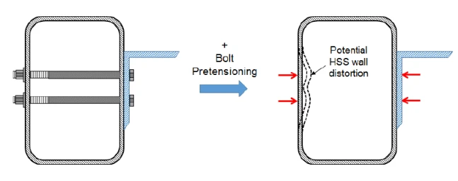
Fig. 2 Potential distortion of the HSS wall when through-bolts are fully pretensioned. Source: J. McCormick, Steel Tube Institute (2017)
2. The bolt behaves as a pin, not as a bolt
The plies are not clamped and may not be in contact. The shank is therefore loaded in shear and bending, and the standard bolt shear check alone does not capture its behavior. The through-bolt must be designed as a pin, with checks of:
- shear,
- bending,
- shear–bending interaction.
3. The bearing resistance of the connected plates is reduced
The head and nut bear only on the outside of the hollow section wall, not on both its outside and inside faces as in a conventional bolted joint. The grip is not restrained against expansion, so the plates are not confined around the hole and can cripple. The bearing resistance is that of a pin, not a bolt. This applies to both the hollow section wall and the connected plate.
Code background
AISC 360-22, §J3.11(b) (§J3.10(c) in AISC 360-16). Bolts that pass fully through an unstiffened HSS are referred to the pin bearing check in §J7:
Rn = 1.8·Fy·Apb, φ = 0.75, Apb = d·tdesign (J7-1)
Here “unstiffened” means a wall not confined by a bolt head and nut on both sides, and not stiffened by infill or reinforcement. Bolt shear (Eq. J3-1) and the remaining limit states of the connected member are checked as usual. AISC 360-16 did not address tear-out for through-bolts; in AISC 360-22 the same section covers bolt tear-out. For closely spaced bolts or bolts near a member end, a rational approach is required.
EN 1993-1-8. There is no specific procedure. By analogy with AISC, the pin rules of Table 3.10 are applied:
Fb,Rd = 1.5·t·d·fy/γM0 (bearing)
MRd = 1.5·Wel·fyp/γM0 (bending)
(MEd/MRd)2 + (Fv,Ed/Fv,Rd)2 ≤ 1 (shear–bending interaction)
Sleeved through-bolts are the case where the bolt inside the hollow section passes through a spacer tube, with tight inner hole diameter, which is equal as the standard bolt holes. The tube prevents distortion of the walls of hollow section in case there is a tension force in bolt. The individual plies are then clamped together similarly to standard bolt connection. And the bolt can be even fully preloaded (CIDECT Design Guide 9, §5.11; Kurobane et al. 2004). In practice, the tube is usually welded into the section as a sleeve (Dutta et al. 1998; McCormick 2017). The connection then behaves more like a conventional bolted joint than a pin joint (McCormick 2017).
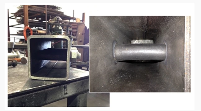
Fig. 3 HSS bolt sleeve reinforcement at through-bolts. Source: M. Manor, Steel Tube Institute (2026)
Benchmark case
Bolt assembly: behavior of a standard bolt
The welded SHS 110×110×10 mm is fabricated from S355 steel and bolted through the section to an 8 mm plate with a standard M16 8.8 bolt. The bolt is modeled with the “Bearing – tension/shear interaction” bolt type, with the shear plane in the thread. The model is loaded only by an axial force of 40 kN in the connected plate. This force loads the bolt in shear (V = 40 kN) and causes a shear force and a torsional moment in the SHS.
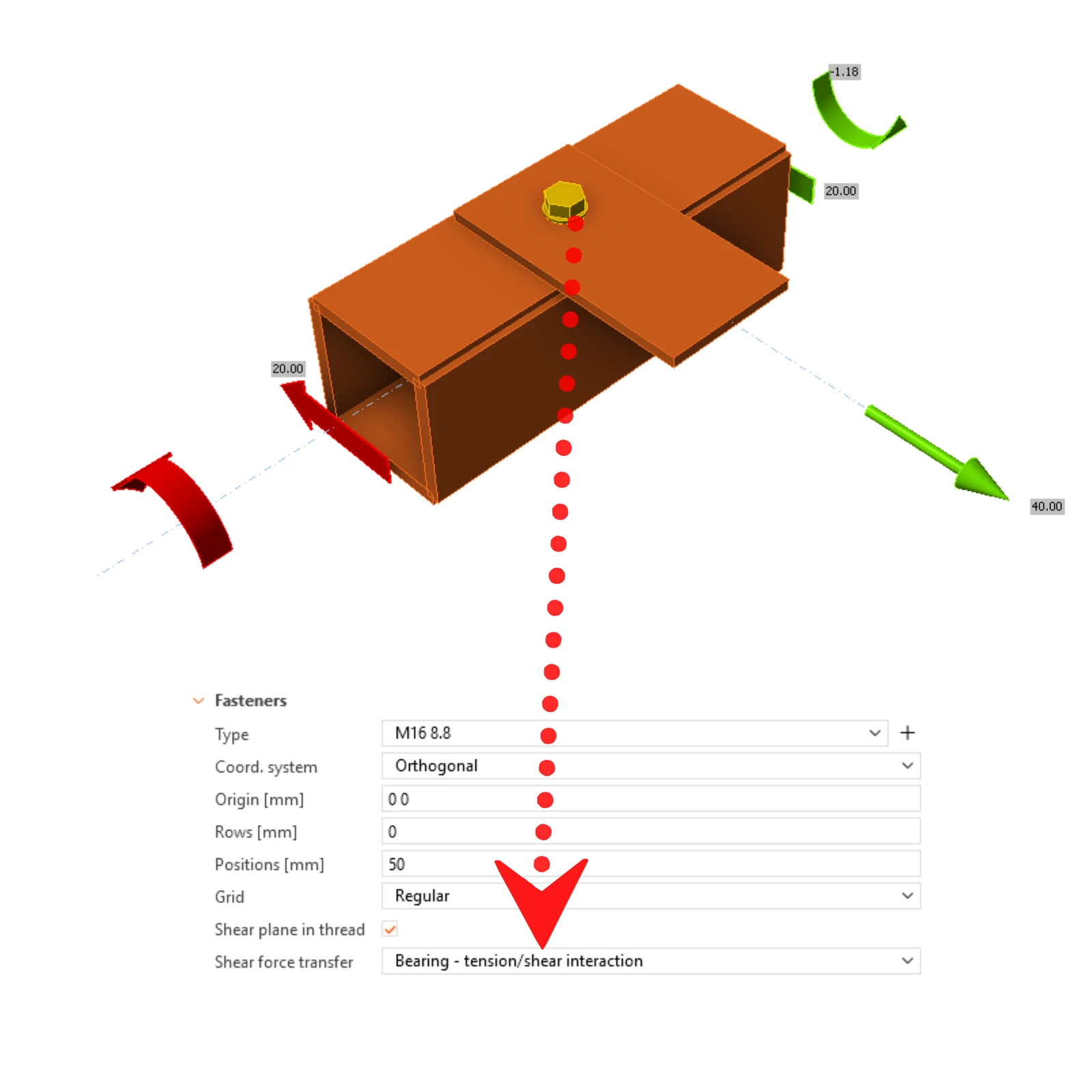
Fig. 4 The benchmark model in IDEA StatiCa Connection with the through-bolt modeled as a standard bolt: the 40 kN force in the plate, the end forces of the SHS and the fastener settings (M16 8.8, shear plane in thread, bearing – tension/shear interaction).
Bolt check to EN 1993-1-8
The shear force is almost fully carried by the first shear plane (40.0 kN). The residual shear force in the second shear plane is negligible (1.56 kN), so the second wall barely participates. The bolt passes with a tension–shear interaction utilization of 69.4 %, governed by the shear utilization of 66.3 %.
The report, however, adds a warning: there is a gap between the connected plates, bending in the bolt is not considered in the numerical model, and the plates are not clamped. The resistances of the bolt in shear and of the plates in bearing may therefore be incorrect. This is the first signal that demands your attention.
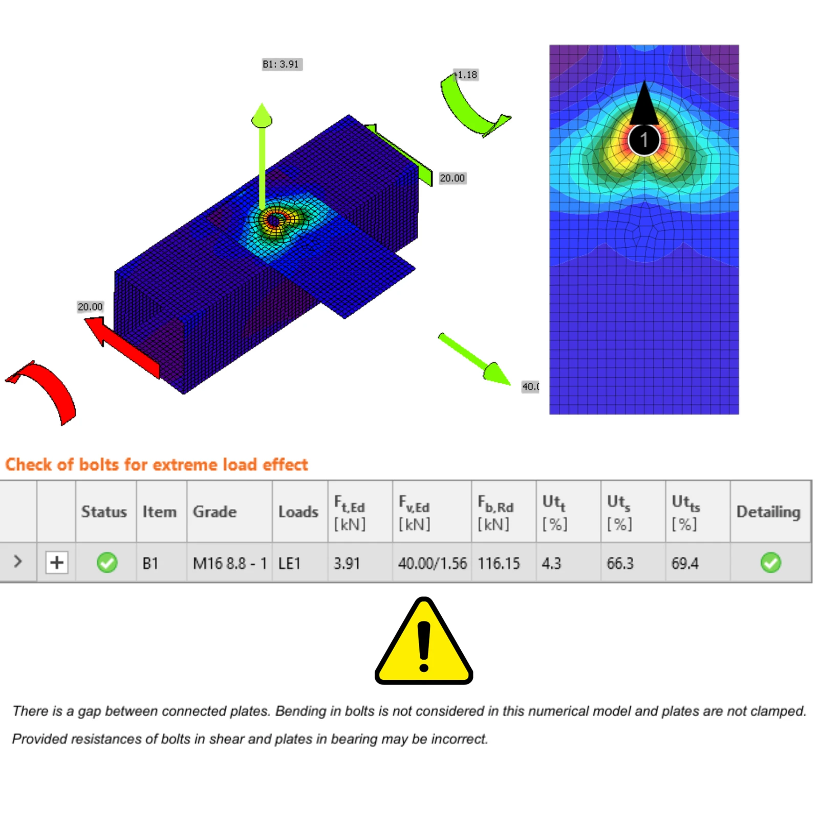
Fig. 5 Bolt check to EN 1993-1-8 (M16 8.8): Ft,Ed = 3.91 kN, Fv,Ed = 40.00/1.56 kN in the two shear planes, Fb,Rd = 116.15 kN, utilization 4.3 % in tension, 66.3 % in shear and 69.4 % in interaction, with the warning issued for through-bolt connections.
An equivalent beam model of the bolt makes the results easy to interpret. It shows the internal forces and the stress distribution along the bolt length and reproduces the same shear utilization, which makes it a simple fidelity check.
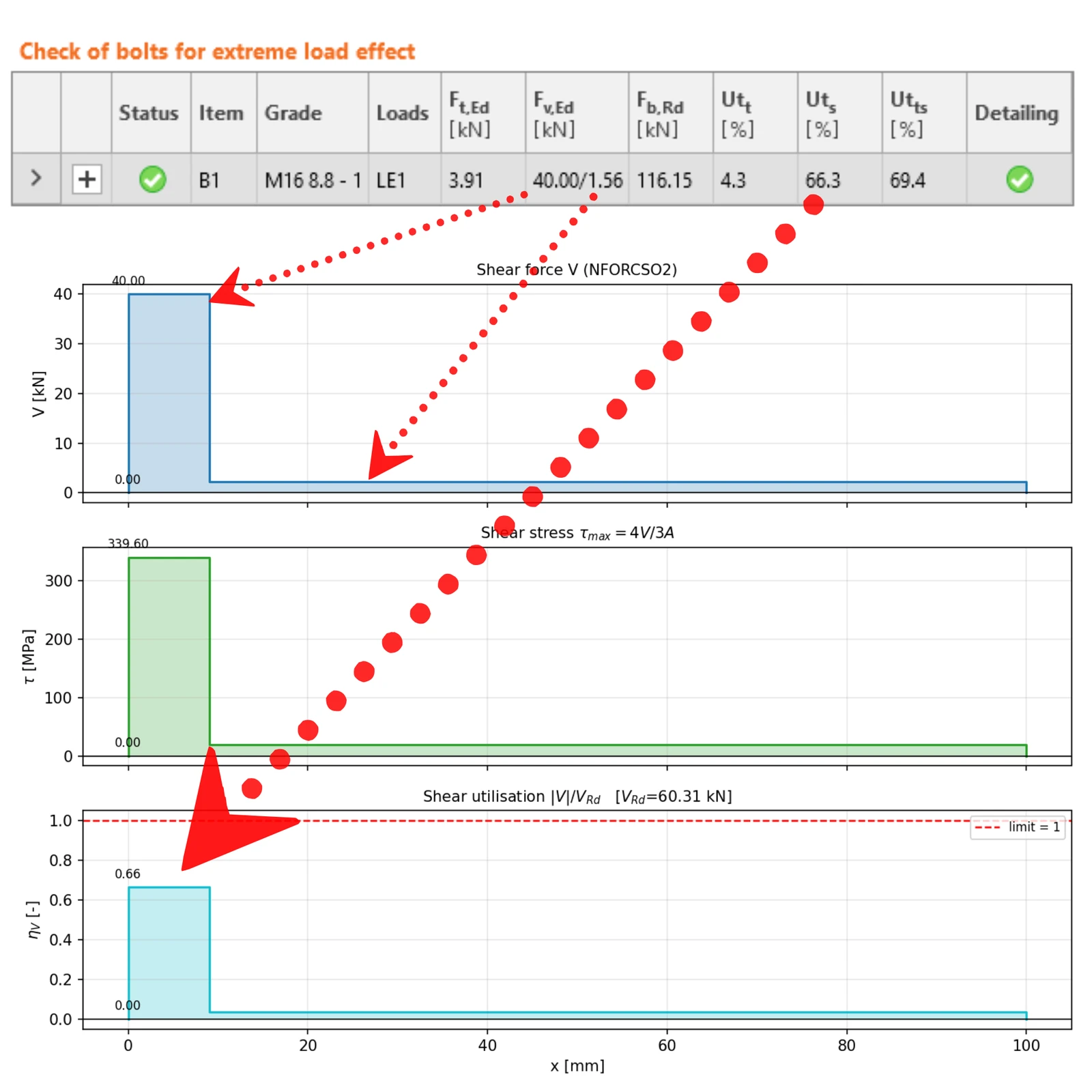
Fig. 6 Equivalent beam model of the bolt: V = 40 kN at the first shear plane, shear stress 4V/3A = 339.6 MPa and shear utilization 0.66 against VRd = 60.31 kN. It confirms the internal forces and the utilization independently of IDEA StatiCa.
Bolt assembly: behavior as a pin
The same model is now built with the “Pin” fastener. The pin element carries the shear force and the bending moment. It does not transmit axial force.
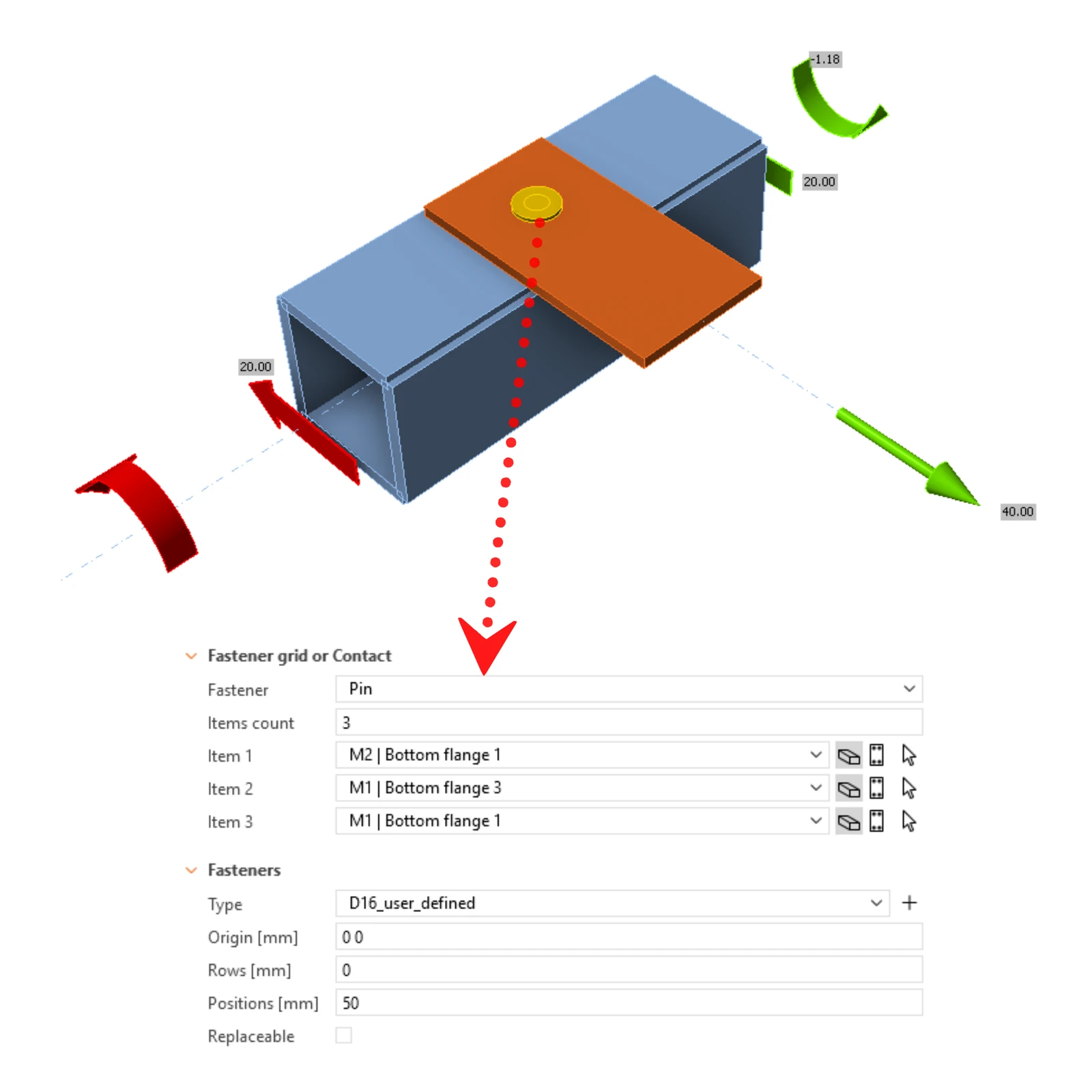
Fig. 7 The benchmark model with the through-bolt modeled as a pin (user-defined D16 pin through the plate and both SHS walls): the 40 kN force in the plate and the end forces of the SHS.
Pin check to EN 1993-1-8
Bending of the pin has the most significant impact on the behavior: on its own, it causes a utilization of 90.9 %. The bearing resistance also drops by about 41 % compared with the bolt approach (68.2 kN against 116.2 kN). Bending combined with the shear force makes the pin check unsatisfactory: the shear–bending interaction reaches 109.5 %, and the pin fails. The bending moment peaks where the pin enters the hollow section.
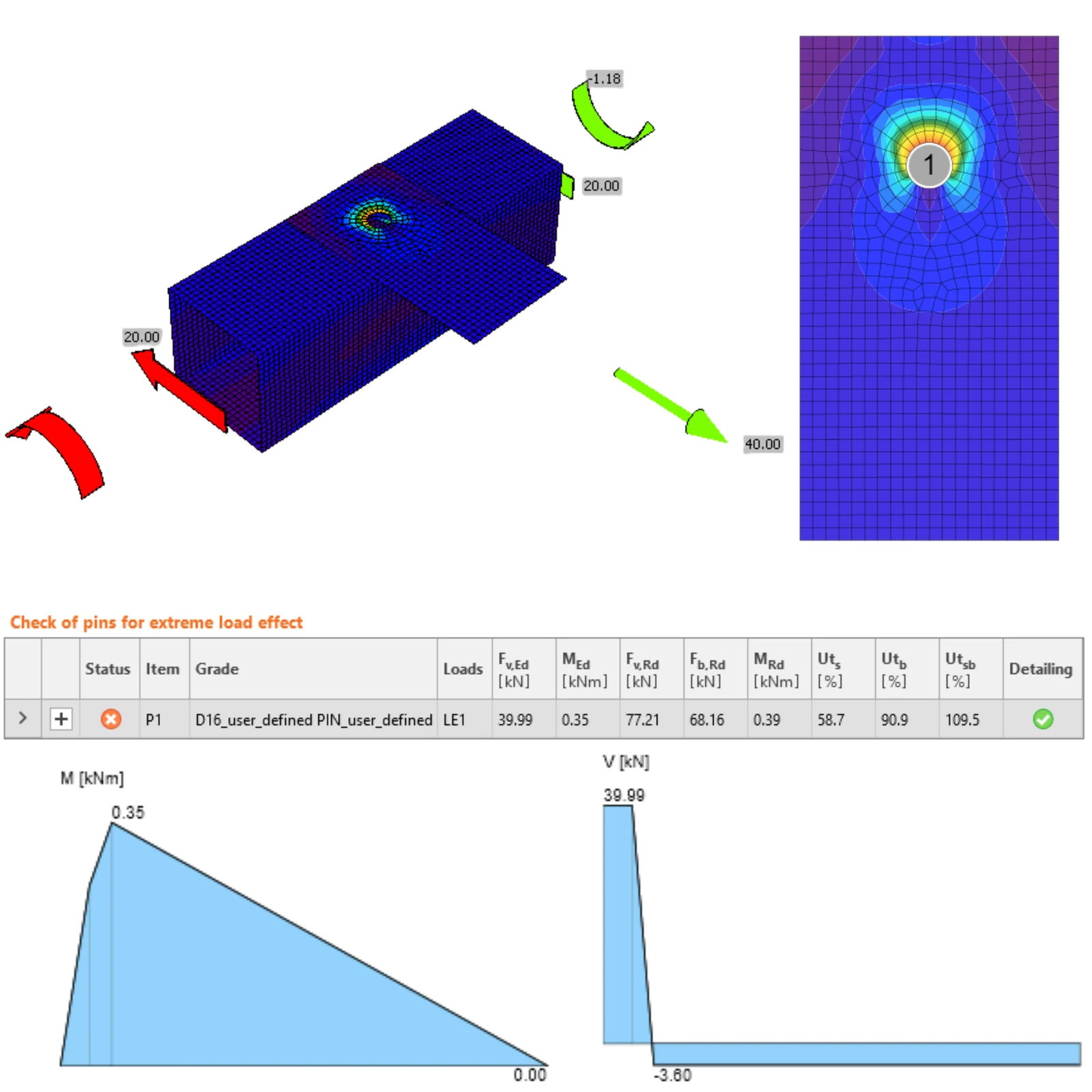
Fig. 8 Pin check (user-defined D16 pin, fyp = 640 MPa): Fv,Ed = 39.99 kN, MEd = 0.35 kNm, Fv,Rd = 77.21 kN, Fb,Rd = 68.16 kN, MRd = 0.39 kNm; utilization in shear 58.7 %, in bending 90.9 % and in interaction 109.5 %. The bending resistance follows EN 1993-1-8, Table 3.10.
| Check (M16 8.8, Fv,Ed = 40 kN) | Modeled as a bolt | Modeled as a pin |
| Shear | 66.3 % | 58.7 % |
| Bending | not checked | 90.9 % |
| Interaction | 69.4 % (tension–shear) | 109.5 % (shear–bending) |
| Bearing resistance Fb,Rd | 116.2 kN | 68.2 kN |
| Result | passes | fails |
Results of the equivalent beam model (pin)
The analytical model can be built according to the rules in the IDEA StatiCa knowledge base article Steel pins.
The analytical beam model agrees closely with the IDEA StatiCa Connection model. In Connection, the load is distributed uniformly over the thickness of the plate that loads the pin; the equivalent model uses a conservative point force instead. This causes small differences between the internal forces and utilizations of the two models, which makes the beam model a useful fidelity and plausibility check.
The shear utilization of 58.7 % is governed by the pin bearing check of the connected plate, not by shear of the pin itself (51.8 %). Bending (0.93) and the shear–bending interaction (1.14) are slightly higher in the equivalent beam model, because of the point force. The pin behaves as expected.
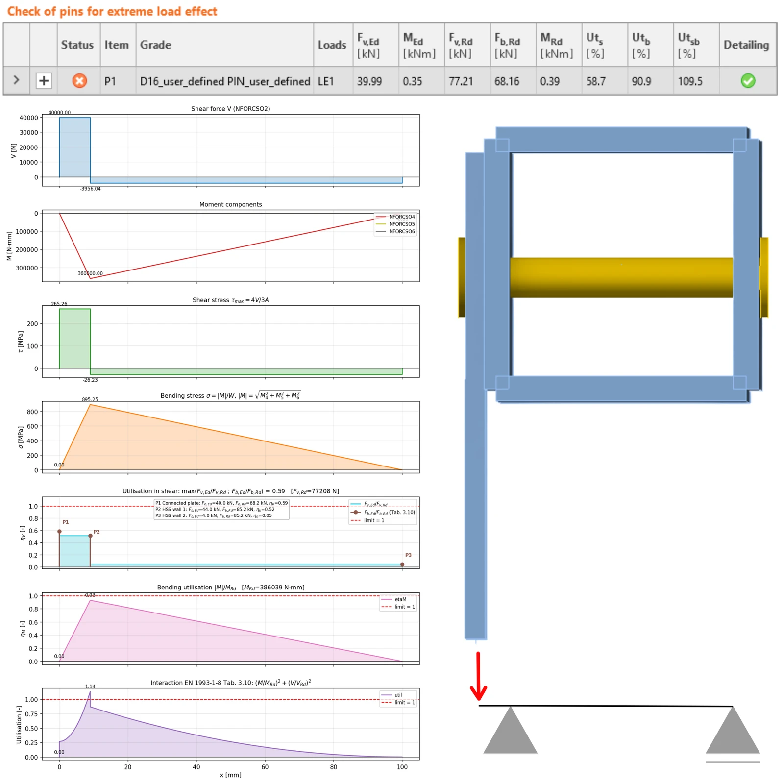
Fig. 9 Equivalent beam model of the through-bolt modeled as a pin: V = 40 kN at the first shear plane, M = 0.36 kNm where the pin enters the SHS wall, bending utilization 0.93 against MRd = 0.386 kNm, interaction 1.14. Pin bearing: 0.59 on the connected plate, 0.52 and 0.05 on the two SHS walls.
Model with fabricated internal sleeves
McCormick (2017) describes the sleeve as one of the most common ways to improve a through-bolt connection:
“One of the most common methods for improving the performance of through-bolt connections is to provide a sleeve (or round tube) for the through bolt to pass through. The sleeve is achieved by drilling a hole in the HSS, inserting a sleeve that has an inner diameter equal to the diameter of a standard hole for the through-bolt, and then welding the sleeve in place (Dutta et al. 1998). The sleeve allows pretensioning of the bolt while preventing distortion of the HSS wall. As a result, the through-bolted connection will behave more like a bolted joint rather than a pin joint.” (McCormick, Steel Tube Institute, 2017)
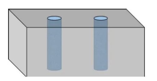
Fig. 10 RHS/SHS member fabricated with internal sleeves.
Sleeves in IDEA StatiCa: non-preloaded bolts
If the welded sleeve is modeled inside the RHS/SHS and the bolt is not preloaded, the through-bolt may be modeled in IDEA StatiCa as a standard bolt, following the article and references above. The sleeve must confine the bolt precisely for the standard bolt model to be valid. Once there is clearance between the sleeve and the bolt, the bolt falls back into pin behavior.
- Even when the sleeve is modeled with the “Stiffening member” manufacturing operation, the report still shows the warning that bending in the bolt is not considered.
- The bearing check is performed on the connected plies
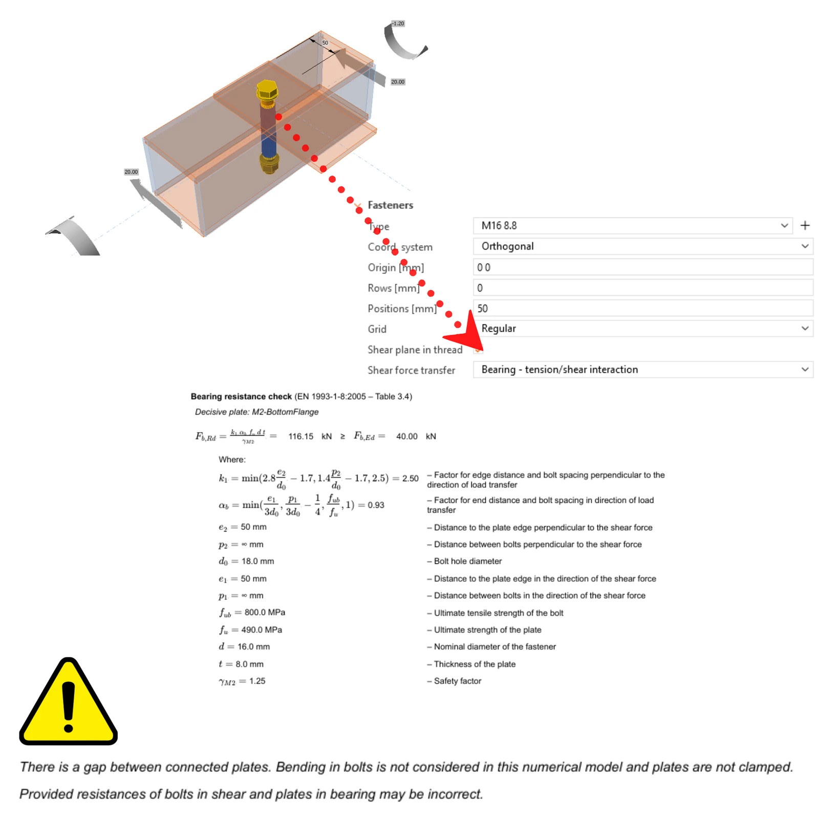
Fig. 11 RHS/SHS connection fabricated with an internal sleeve and a non-preloaded M16 8.8 bolt: bearing resistance check to EN 1993-1-8 Table 3.4 and the warning about the gap between the connected plates.
Sleeves in IDEA StatiCa: friction bolts
IDEA StatiCa Connection does not allow friction (slip-resistant) bolts in this model. The analysis stops with the message “Friction type bolts cannot be used if there is a gap between the plates”. There is a reason for this:
- In the model, the preload is not transferred into the sleeve. The bolt is stiffened in shear, and the tangential forces from the bolt act on the hole in tension and compression, but in the axial direction the bolt behaves as a standard bolt and no prestressed state is created. The sleeve is not compressed by the preload, so the resulting stress state would be misleading.
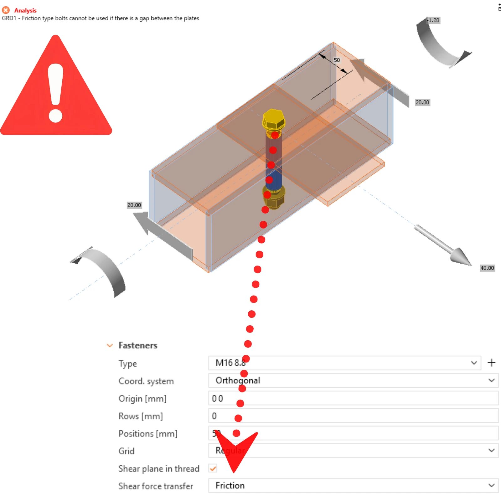
Fig. 12 RHS/SHS connection fabricated with an internal sleeve and a preloaded (friction) bolt: the analysis reports that friction type bolts cannot be used if there is a gap between the plates.
Conclusion
- An unsleeved through-bolt is a pin, not a bolt. It cannot be preloaded, the plies are not clamped, and the shank works in shear and bending.
- The standard bolt check is unsafe here. In the benchmark (SHS 110×110×10, 8 mm plate, M16 8.8, 40 kN) the bolt check passes at 69.4 %. The pin check fails at 109.5 % in shear–bending interaction, with bending alone at 90.9 %.
- Read the warning in the report. IDEA StatiCa Connection flags the gap between the plates: bending in the bolt is not considered and the bolt shear and plate bearing resistances may be incorrect.
- Bearing resistance drops by about 41 %. Pin bearing on the 8 mm plate gives 68.2 kN against 116.2 kN for bolt bearing.
- Model it as a pin in IDEA StatiCa Connection and assign the bolt grade to the pin material. The pin carries no axial force, so check tension effects separately if necessary.
- A welded sleeve restores bolt behavior. With a tight-fitting sleeve, the through-bolt can be modeled as a standard bearing bolt. Friction (preloaded) bolts cannot be analyzed in IDEA StatiCa Connection when there is a gap between the plies.
References
- AISC (2022). Specification for Structural Steel Buildings, ANSI/AISC 360-22. American Institute of Steel Construction, Chicago, IL.
- AISC (n.d.). Design Guide 24: Hollow Structural Section Connections, 2nd edition. American Institute of Steel Construction, Chicago, IL.
- CEN (2005). EN 1993-1-8:2005 Eurocode 3: Design of steel structures – Part 1-8: Design of joints. European Committee for Standardization, Brussels.
- Dutta, D., Wardenier, J., Yeomans, N., Sakae, K., Bucak, Ö. and Packer, J.A. (1998). Design Guide 7: For Fabrication, Assembly and Erection of Hollow Section Structures. CIDECT, TÜV-Verlag, Köln.
- Kurobane, Y., Packer, J.A., Wardenier, J. and Yeomans, N. (2004). Design Guide 9: For Structural Hollow Section Column Connections. CIDECT, TÜV-Verlag, Köln.
- Manor, M. (2026). HSS Bolted Connections: Keep It Together With a Bolt of Confidence. Steel Tube Institute. steeltubeinstitute.org
- McCormick, J. (2017). Connecting Hollow Structural Section Members with Through-Bolts. Steel Tube Institute, July 2017. steeltubeinstitute.org
The authors of the article: Lukas Juricek, Pavel Kalab and Martin Vild