Steel pins
Pins can be used for modeling pin connections as well as help in cases where a one-bolt connection doesn't meet the requirement in EN 1993-1-8, 3.13.1 (2) and has to be checked as a beam element with bending – pin.
How to model a pin
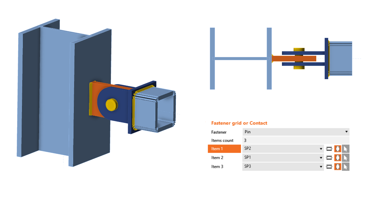
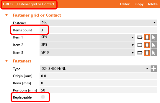
There is a Pin type of fastener within the operation Fastener grid and Contact. When Pin is selected, the count of items is automatically changed to three, which is the minimum number of connected plates.
The pin can also be designed as Replaceable, which governs the used checks according to code.
A member connected by a pin must have the model type N-Vy-Vz specified, otherwise, the analysis leads to a singularity.
The contact between plates is created automatically if the distance between connected parallel plates is less than 2 mm. If the gap is bigger than 2 mm, the contact is not created.
Pins in the project material database
The geometric parameters of a pin (pin diameter, material, hole size, pin head...) can be defined in the Materials tab similarly to bolt assemblies. The diameter of a pin can be selected from the predefined material library.
Structural steel material (e.g., S355) is used as the default material for pins. In case a steel bolt material (e.g., 8.8) or any other type of material needs to be defined for pins, it can be done by editing the properties of added structural steel material (fu, etc.).
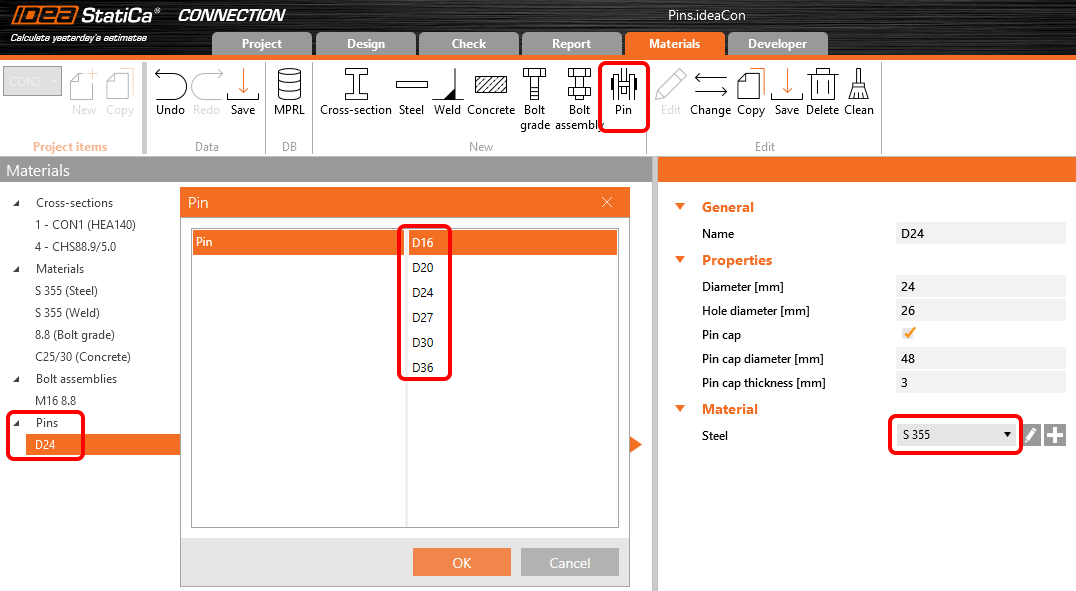
A Pin cap can be turned on, but it doesn't influence the checks or analysis, only the visual presentation of pins in the 3D scene.
Code checks of pinned connections
Checks are provided according to EN 1993-1-8, 3.13.2.
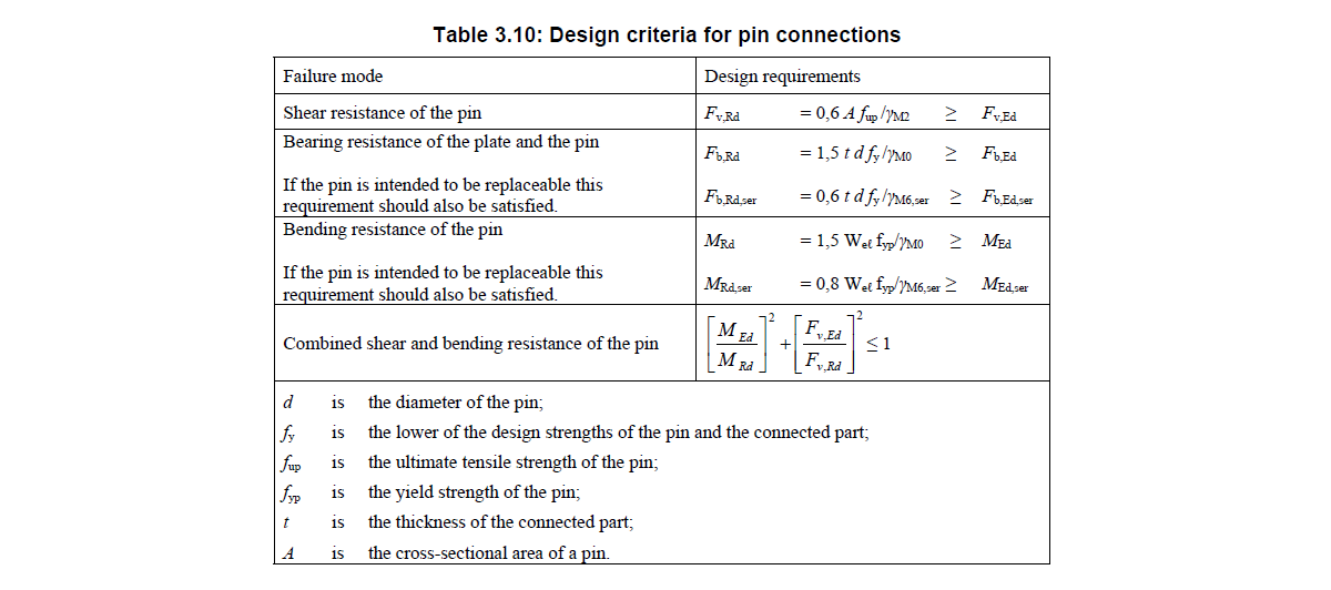
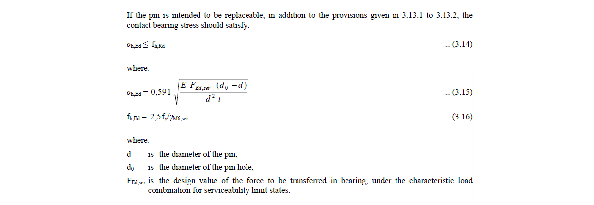
If the pin is set as replaceable, different checks are used, according to Table 3.10 and Equation 3.14.
When the fire resistance analysis type is performed, the replaceable setting of used pins is ignored, and all pins in the model are checked as non-replaceable.
Pins in the results and report
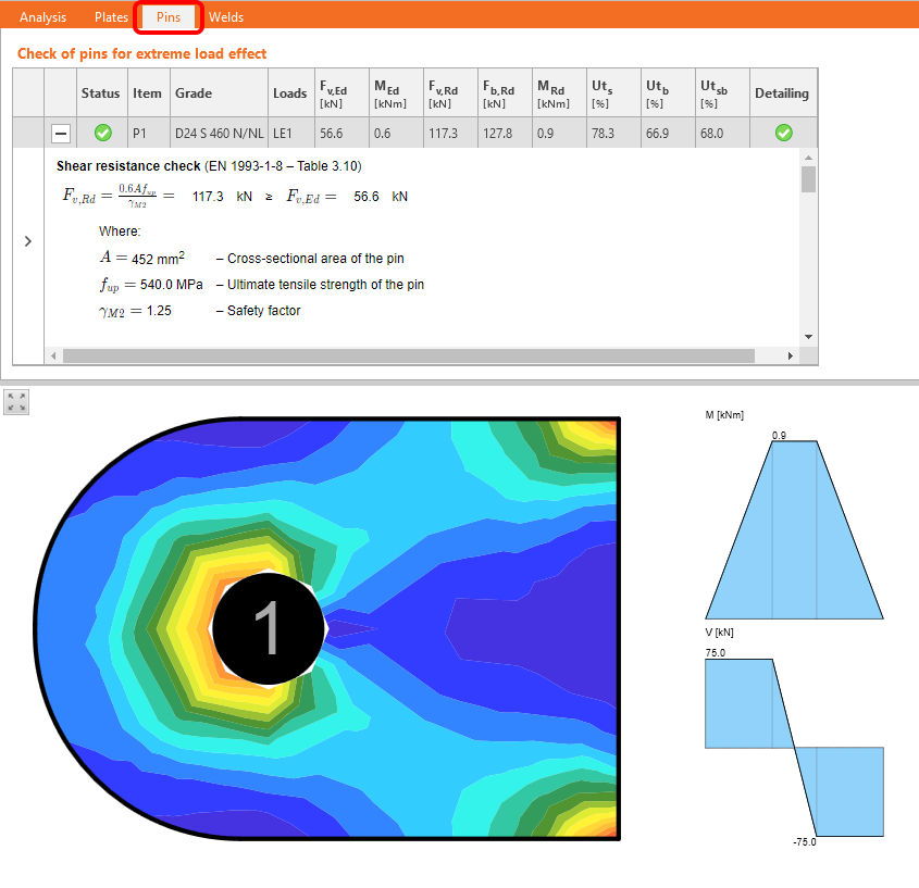
There is a check tab for pins with detailed results and code equations listed in the Check tab. Also, the bending moment diagram for the pin is displayed along with the stress/strain in the connected plate.
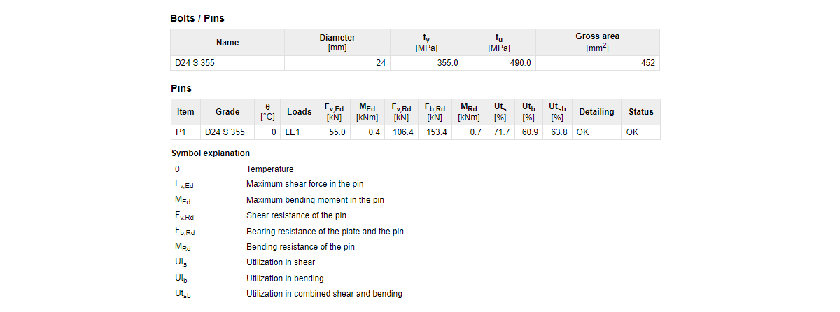
All relevant input data and result data of pins are included in the report.
Detailing checks for pinned connections
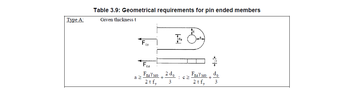
Basic detailing checks are provided according to Table 3.9 – type A. For finding the edge distances "a" and "c", identical logic is used as the one used for determining the edge distances of bolts (dependent on vector direction).
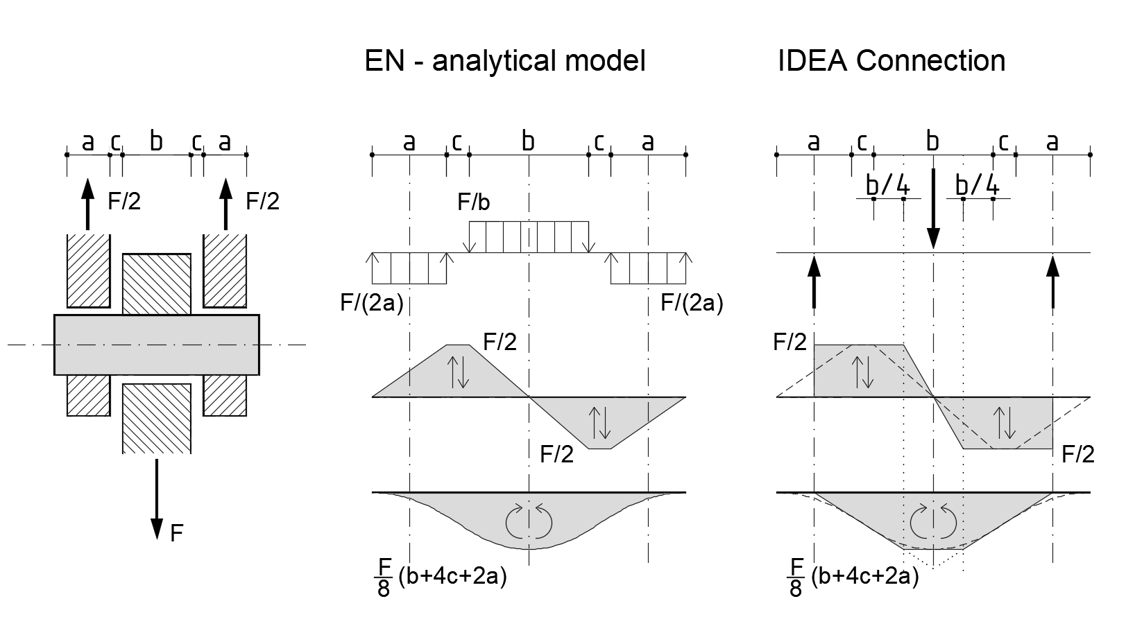
The CBFEM analytical model of a pin
Pins in CBFEM are modeled as linear elastic beam elements. The pin model is implemented in such a way that individual plates are not connected in the direction of the pin axis, and, thus, no normal force is generated in it. Only shear force and bending moment are active.
In the Connection app, the forces are applied to the pin as point loads in the axis of connected plates, and the bending moment diagram in a pin has a simplified linear shape compared to the analytical model in the Eurocode. Internal forces in the pin are evaluated and presented in a quarter of the inner plate thickness, which ensures that shear force and bending moment maximum values used for the code-checks are identical to extreme values from the analytical Eurocode model.
Note: Pins are available for Eurocode (EN) only.
Released in IDEA StatiCa version 24.0.
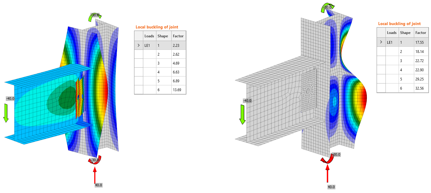
Buckling calculation of models with pins
The buckling analysis method for pinned connections has been refined to deliver more realistic and less conservative results. The updated formulation in version 25.1 more accurately represents the rotational stiffness and boundary conditions of pinned joints, aligning the calculated buckling behavior with that of equivalent bolted configurations. This improvement ensures a closer correlation between analytical prediction and physical performance, enhancing the reliability of stability assessments in models containing pins.
Released in IDEA StatiCa version 25.1.