Learning Module: Verification
Connection design can be difficult to teach, given the detailed nature of the topic and the fundamentally three-dimensional behavior of most connections. However, connections are critically important, and lessons learned in the study of connection design, including load path and identification and evaluation of failure modes, are general and applicable to structural design broadly. IDEA StatiCa uses a rigorous nonlinear analysis model and has an easy-to-use interface with a three-dimensional display of results (e.g., deformed shape, stress, plastic strain) and thus is well suited for the exploration of the behavior of structural steel connections. Building on these strengths, a suite of guided exercises that use IDEA StatiCa as a virtual laboratory to help students learn about concepts in structural steel connection behavior and design was developed. These learning modules were primarily targeted to advanced undergraduate and graduate students but were made suitable for practicing engineers as well. The learning modules were developed by Associate Professor Mark D. Denavit from the University of Tennessee, Knoxville.
Learning Objective
After performing this exercise, the learner should be able to compare the results of IDEA StatiCa to traditional methods based on the AISC Specification.
Background
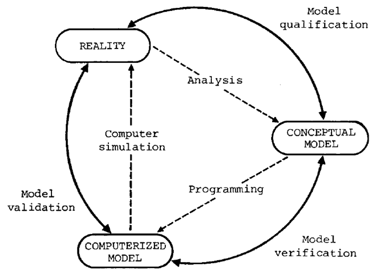
The use of software tools developed by others is a practical necessity in engineering practice. Yet, when signing a set of drawings, an engineer is taking personal responsibility for the design. Even in the ideal situation where the engineer is using software to inform, and not replace, their judgment, the engineer must trust those software tools to produce results that are informative. For computational simulations, verification and validation are the primary methods for building and quantifying this trust (Oberkampf et al. 2002).
Verification refers to the process of determining that a model implementation accurately represents the developer's conceptual description of the model and the solution to the model. Validation refers to the process of determining the degree to which a model is an accurate representation of the real world from the perspective of the intended uses of the model.
Relationships between reality, a conceptual model, and a computerized model (SCS Technical Committee on Model Credibility 1979)
For IDEA StatiCa, the intended use of the component-based finite element model (CBFEM) is as a numerical design calculation to determine if a connection conforms with standards and is safe, not necessarily to produce results as close as possible to the expected behavior of the connection. Safety factors are incorporated, and conservatism is tolerated. Given that the design assumptions that form the conceptual model for IDEA StatiCa are based on standards for design such as the AISC Specification (AISC 2022), verification for IDEA StatiCa includes comparisons to the AISC Specification. Verification also includes other comparisons to ensure the finite element model correctly exhibits the assumed mechanics of the connections. Validation for IDEA StatiCa includes comparison to results of physical experiments.
Given that IDEA StatiCa and the AISC Specification have the same intent, an apples-to-apples comparison can be made by examining the maximum loads that each method permits to be applied to a particular connection. In this comparison, the determination of the maximum applied loads should be done using the procedures and settings that would be used by an engineer in practice. Comparing IDEA StatiCa to experimental results for validation is less straightforward and typically involves the removal of safety factors and use of measured material and geometric properties in IDEA StatiCa.
As a software company, IDEA StatiCa performs extensive verification and validation on their software as documented on their website and in books (Wald et al. 2020, Denavit et al. 2024). However, the user can also perform verification and validation. Doing so helps build trust in the software, knowledge about CBFEM, and can deepen understanding of the strength and behavior of connections.
The process of verification is analogous to the execution of the scientific method with a hypothesis that the model produces correct results and the need to test that hypothesis through a (virtual) experiment. As with any experiment, research design is critical to make the experiment as decisive as possible. Challenging cases should be evaluated, but it is often best to start with simpler cases.
This exercise guides the learner through the verification of IDEA StatiCa in comparison to the AISC Specification for connections that have bolts in combination with welds. Requirements for bolts in combination with welds are given in AISC Specification Section J1.8. This section includes a general requirement: “Bolts shall not be considered as sharing the load in combination with welds, except in the design of shear connections on a common faying surface where strain compatibility between the bolts and welds is considered.” The section also includes a permissible method for considering strain compatibility for a specific class of connections and the statement “In joints with combined bolts and longitudinal welds, the strength of the connection need not be taken as less than either the strength of the bolts alone or the strength of the welds alone.”
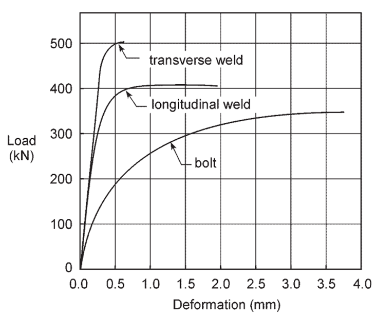
As described in the commentary on the AISC Specification, the complication with combining bolts and welds is that they do not achieve their ultimate strength at the same level of deformation.
Representative load vs. deformation characteristics (Kulak and Grondin 2003)
Pretensioning bolts increases the stiffness of the connection, enabling more effective load sharing between the bolts and welds. This is why the permissible method described in AISC Specification Section J1.8 applies only to connections with pretensioned bolts.
Strength checks for bolts and welds are independent in IDEA StatiCa with no special handling of when bolts and welds share load. Given the explicit modeling of the stiffness of bolts, welds, members, and connecting elements, strain compatibility is always considered in IDEA StatiCa. When bolts and welds share load, the required strength of each is based on their relative stiffness and the available strength is computed as usual. The validity of this approach can be established through comparison.
Connection
The connection examined in this exercise splices two plate tension members. Pretensioned bolts and welds are used in combination on all faying surfaces. Various weld lengths are examined. For simplicity, the weld length is only adjusted on the right-hand side of the splice connection. The connection was designed such that the strength of bolts and welds controls over that of the member and connecting elements.
Procedure
The procedure for this exercise assumes that the learner has a working knowledge of how to use IDEA StatiCa (e.g., how to navigate the software, define and edit operations, perform analyses, and look up results). Guidance for how to develop such knowledge is available on the IDEA StatiCa support center.
Before beginning the exercise, it is helpful to review AISC Specification Section J1.8 and associated commentary, as well as the description of how IDEA StatiCa handles bolts in combination with welds in this catalog entry.
Retrieve the IDEA StatiCa file for the example connection provided with this exercise. Open the file in IDEA StatiCa Connection. To perform the exercise, follow the narrative, complete the tasks, and answer the questions.
Examine the connection with bolts only.
Examine the connection with welds only (L = 6 in.).
Examine the connection with both bolts and welds (L = 6 in.).
Verification should be performed over a range of parameters. The relative strength of bolts and welds is an important parameter for the method for combining the strengths of bolts and welds in the AISC Specification. The relative strength can be varied by adjusting the length of the welds. Examine the connection with a variety of weld lengths.
Beyond comparisons, verification includes analyzing the data to make conclusions and identify directions of further investigation.
References
AISC. (2022). Specification for Structural Steel Buildings. American Institute of Steel Construction, Chicago, Illinois.
AWS. (2020). Structural Welding Code—Steel. American Welding Society. Doral, Florida.
Denavit, M. D., Nassiri, A., Mahamid, M., Vild, M., Wald, F., and Sezen, H. (2024). Steel Connection Design by Inelastic Analysis. John Wiley & Sons, Inc., Hoboken, New Jersey.
Kulak, G. L., and Grondin, G. Y. (2003). “Strength of Joints that Combine Bolts and Welds.” AISC Engineering Journal, 40(2), 89–98.
Oberkampf, W. L., Trucano, T. G., and Hirsch, C. (2002). “Verification, Validation and Predictive Capability in Computational Engineering and Physics.” Proceedings of the Foundations for Verification and Validation on the 21st Century Workshop, Laurel, Maryland, 1–74.
SCS Technical Committee on Model Credibility. (1979). “Terminology for model credibility.” Simulation, SAGE Publications Ltd STM, 32(3), 103–104.
Wald, F., Šabatka, L., Bajer, M., Jehlička, P., Kabeláč, J., Kožich, M., Kuříková, M., and Vild, M. (2020). Component–Based Finite Element Design of Steel Connections. Czech Technical University in Prague.


