
Learning Module: Load Path and Failure Modes of Simple Shear Connections
Connection design can be difficult to teach, given the detailed nature of the topic and the fundamentally three-dimensional behavior of most connections. However, connections are critically important, and lessons learned in the study of connection design, including load path and identification and evaluation of failure modes, are general and applicable to structural design broadly. IDEA StatiCa uses a rigorous nonlinear analysis model and has an easy-to-use interface with a three-dimensional display of results (e.g., deformed shape, stress, plastic strain) and thus is well suited for the exploration of the behavior of structural steel connections. Building on these strengths, a suite of guided exercises that use IDEA StatiCa as a virtual laboratory to help students learn about concepts in structural steel connection behavior and design was developed. These learning modules were primarily targeted to advanced undergraduate and graduate students but were made suitable for practicing engineers as well. The learning modules were developed by Associate Professor Mark D. Denavit from the University of Tennessee, Knoxville.
Learning Objective
After performing this exercise, the learner should be able to describe the load path for a simple shear connection and identify relevant failure modes.
Background
Load Path
Loads applied to a structure are transferred through members and connections before eventually being resisted by the ground. Tracking the path of the load from its point of load application to the ground can be a helpful qualitative exercise to ensure the path is continuous, and that each component along the path has sufficient stiffness and strength. Tracking a subset of the load path through a connection provides the same benefits.
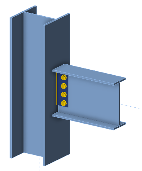
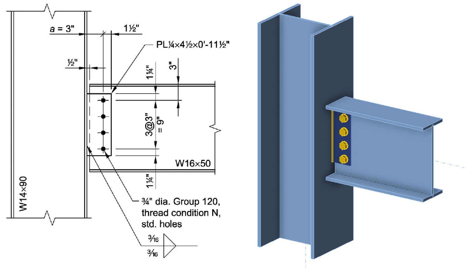
Consider, for example, the single plate shear connection between a wide flange steel beam and a wide flange steel column shown below. Shear in the beam is transferred to axial load in the column as follows:
- Shear in the beam is primarily resisted by the web.
- The beam web bears on the bolts.
- The bolts transfer load from the plane of the beam web to the plane of the connection plate through shear.
- The bolts bear on the connection plate.
- The connection plate transfers load from the bolt line to the weld line through shear.
- The welds transfer load from the connection plate to the column flange through shear.
- The load spreads through the column cross-section.
In traditional connection design, load paths such as this can help engineers develop a checklist of limit states and ensure every step along the path has sufficient stiffness and strength. In design by inelastic analysis, load paths can help engineers by providing a mental model of connection behavior against which the results of numerical analyses can be compared.
The load path for transferring shear in the beam through the single plate shear connection is relatively direct and each step in the path can efficiently be made stiff and strong. This is not the case for transferring moment in the beam. Moment in the beam is primarily resisted by the flanges. Since the beam flanges are not connected to the column, flexural stresses must be funneled down to the web, which cannot resist much moment. The bolt group can resist moment, but far less efficiently than it can resist concentric shear. Attempting to find a load path for moment clarifies why this connection is considered a simple shear connection.
Simple Shear Connections
One of the major classifications of connections at the ends of beams is based on rotational stiffness. Fully restrained connections are stiff enough to assume no relative rotation between members. Simple shear connections are flexible enough to assume no moment is transmitted through the connection.
While it is assumed that no moment is transmitted through a simple connection, shear is transmitted and the connection occurs over a length, therefore, moments are induced in the connection. Only one point along the length of the beam has zero moment.
In reality, the location of the point of zero moment is based on the relative stiffnesses of the beam, the support, and the connection and can shift as the beam is loaded. In design, the location of the point of zero moment in a simple shear connection is chosen. Based on the lower bound theorem of limit analysis (e.g., as described in Section 2.1.1 of Tamboli, 2017), any reasonable point can be chosen if the choice is applied consistently throughout the design and ductile behavior is ensured. Common choices for the point of zero moment include the weld line and the bolt line. Moment diagrams for these cases are shown in the figures below.
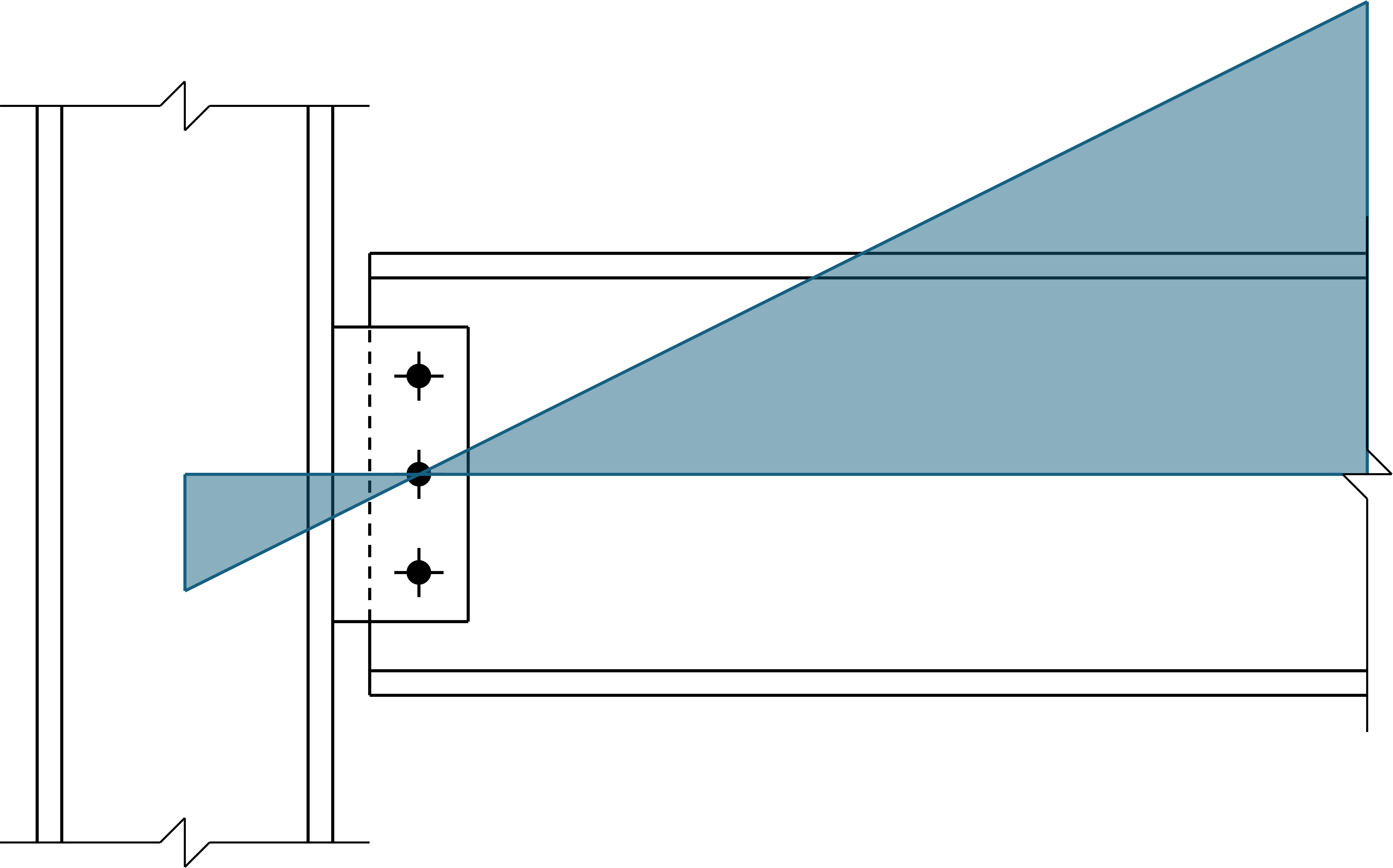
Moment diagram in a simple shear connection with the point of zero moment at the bolt line.
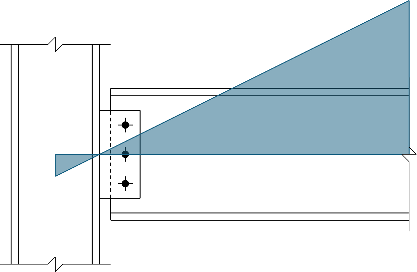
Moment diagram in a simple shear connection with the point of zero moment at the weld line.
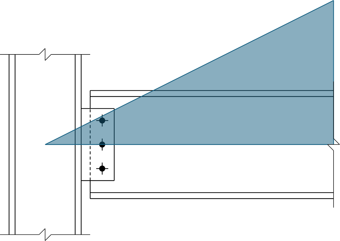
Moment diagram in a simple shear connection with the point of zero moment at the work point.
In documents published by AISC, it is common for the point of zero moment to be located at the face of the supporting member. For a single plate shear connection, this is the weld line, thus it is common for the bolt group to be checked for moment in addition to shear.
Connection
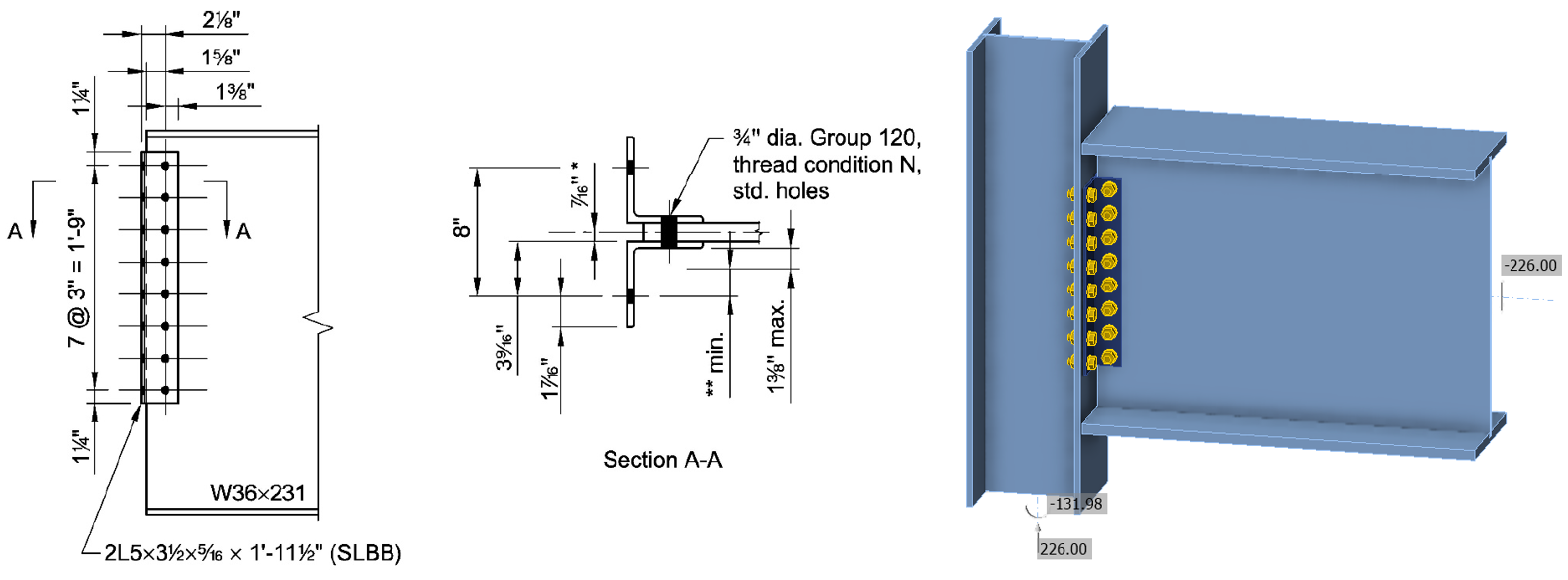
Connection examined in this exercise is based on AISC Design Examples V16.0, Example II.A-17A
Procedure for Single Plate Shear Connection
The procedure for this exercise assumes that the learner has a working knowledge of how to use IDEA StatiCa (e.g., how to navigate the software, define and edit operations, perform analyses, and look up results). Guidance for how to develop such knowledge is available on the IDEA StatiCa Support center.
This detailed procedure focuses on the connection with the point of zero moment located at the bolt line. In US practice, the point of zero moment is typically assumed to be located at the face of the supporting member. The point of zero moment is located at the bolt line in this example for a simpler evaluation of the strength and behavior of the bolts.
The load path for this connection is described in the background section of this document. To perform the exercise, follow the narrative, complete the tasks, and answer the questions.
Retrieve the IDEA StatiCa file for this first connection provided with this exercise. Open the file in IDEA StatiCa. For the beam member, ensure that “Forces in” is set to “Bolts”. Note that this connection, based on AISC Design Examples V16.0, Example II.A-17A, has a required strength calculated from LRFD load combinations of Ru = 49.6 kips. Note that the design example and the (Catalog of AISC limit states and design requirements) can be helpful when answering the questions.
Beam
The shear load applied to the beam is primarily resisted by the beam web. The member strength check of AISC Specification Chapter G for shear yielding ensures that the web has sufficient strength, and no additional connection limit states apply. If the beam was coped, shear rupture or block shear rupture could have applied.
In IDEA StatiCa, the strength of the beam web is checked against the 5% plastic strain limit (a member strength check should also be performed outside of IDEA StatiCa). Under the given loads, the beam does not experience any plastic strain.
The equivalent stress in the web around the bolts is approximately 20 ksi, indicated by the green color in the figure below.
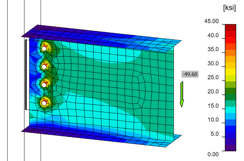
Note that the stresses in the flanges at the end of the beam are very low, indicating that the moment at the end of the beam is also very low.
Bolt Group
The bolts are concentrically loaded since the point of zero moment is assumed to be at the bolt line.
For each limit state, find where the results of the check are displayed in IDEA StatiCa and compare IDEA StatiCa’s calculations to your own.
Connection Plate
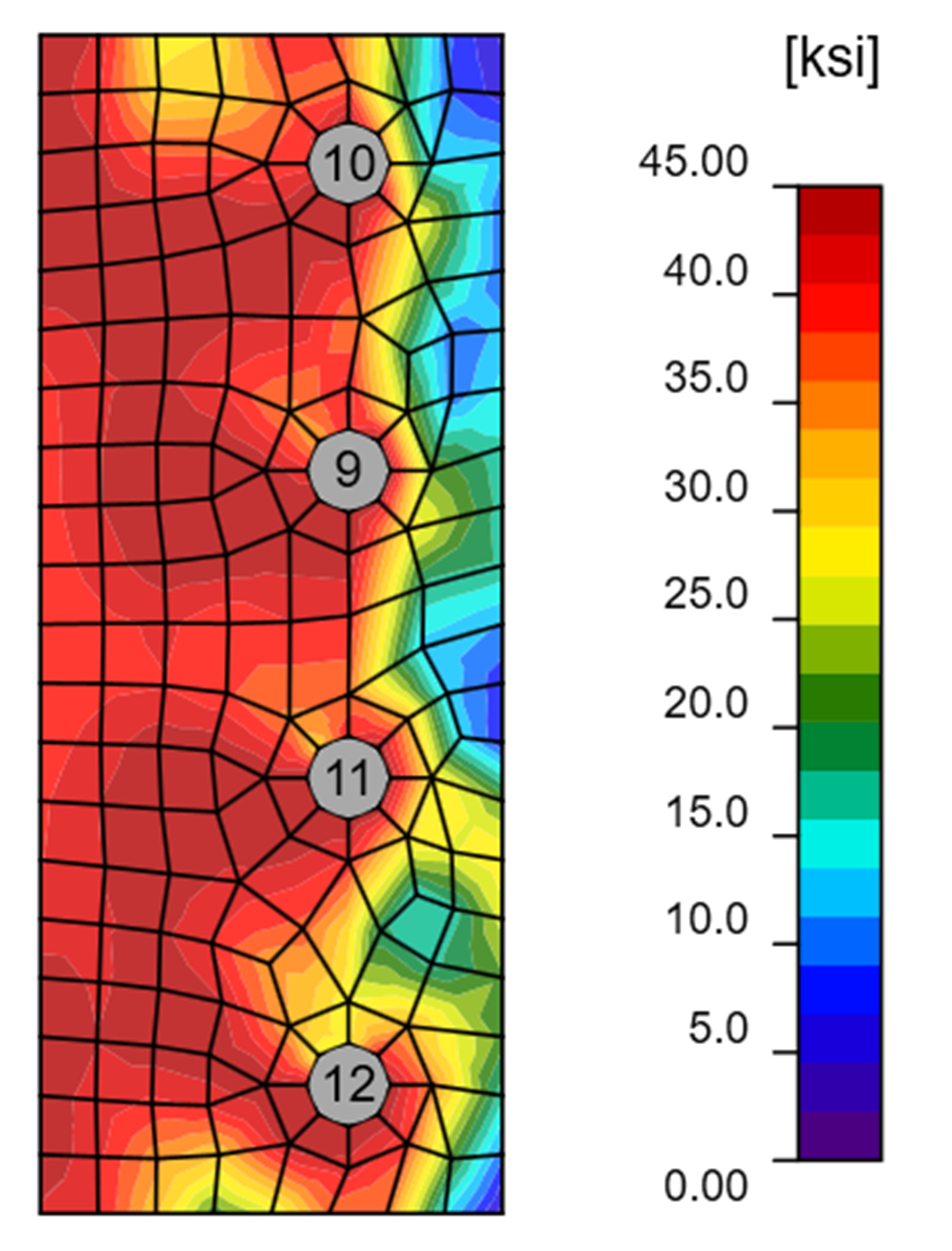
The connection plate transfers load from the bolt line to the weld line through shear. The plate also experiences a bending moment at the weld line equal to the required shear force (49.6 kips) times the eccentricity between the bolt line and the weld line (3 in.).
The average shear stress in the connection plate is τ = Ru/(l×t) = (49.6 kips)/(11.5 in. × 0.25 in.) = 17.3 ksi. Multiplying by \(\sqrt{3}\) to convert to an equivalent stress gives 30 ksi. The equivalent stress from IDEA StatiCa is greater (see figure below), likely due to a combination of the required moment strength and twisting of the plate.
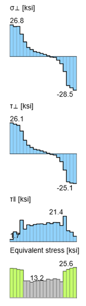
Welds
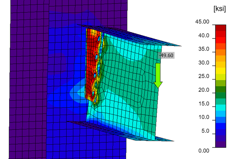
The welds transfer load from the connection plate to the column flange through shear.
In traditional calculations, the strength of eccentrically loaded weld groups is typically checked using the instantaneous center of rotation (IC) method and the tables in Part 8 of the AISC Manual. The approach to check the strength of welds in IDEA StatiCa is similar to that of the IC method. The weld group is broken into short segments, which are each assumed to resist a concentric load. The stresses due to bending and twisting of the connection plate are greatest at the ends of the welds. The stresses due to shear of the connection plate is greatest in the middle of the welds.
Column
No specific limit state applies to the column flange at the location of the weld. In traditional calculations, it is common to ensure that the connection thickness meets the recommendation of AISC Manual Equation 9-6.
The stresses from the weld spread through the column cross-section and are combined with other stresses from loads applied above (not included in the IDEA StatiCa model). Member strength checks apply to the column.
General Procedure
For a more open-ended experience or for connections other than the single plate shear connection, complete the following tasks:
- Select one of the connections described below.
- Review the design example upon which the connection is based.
- Retrieve the IDEA StatiCa file for the connection provided with this exercise. Open the file in IDEA StatiCa.
- Describe the load path for this connection.
- Answer the following questions for each step in the load path:
- What is the required strength?
- What failure modes need to be considered?
- How are the failure modes considered in traditional calculations?
- How are the failure modes considered in IDEA StatiCa?
For further exploration, repeat all or portions of the exercise with the following variations:
- The connection is slip-critical.
- The location of the point of zero moment is different.
Connection 2 based on AISC Design Examples V16.0, Example II.A-1A
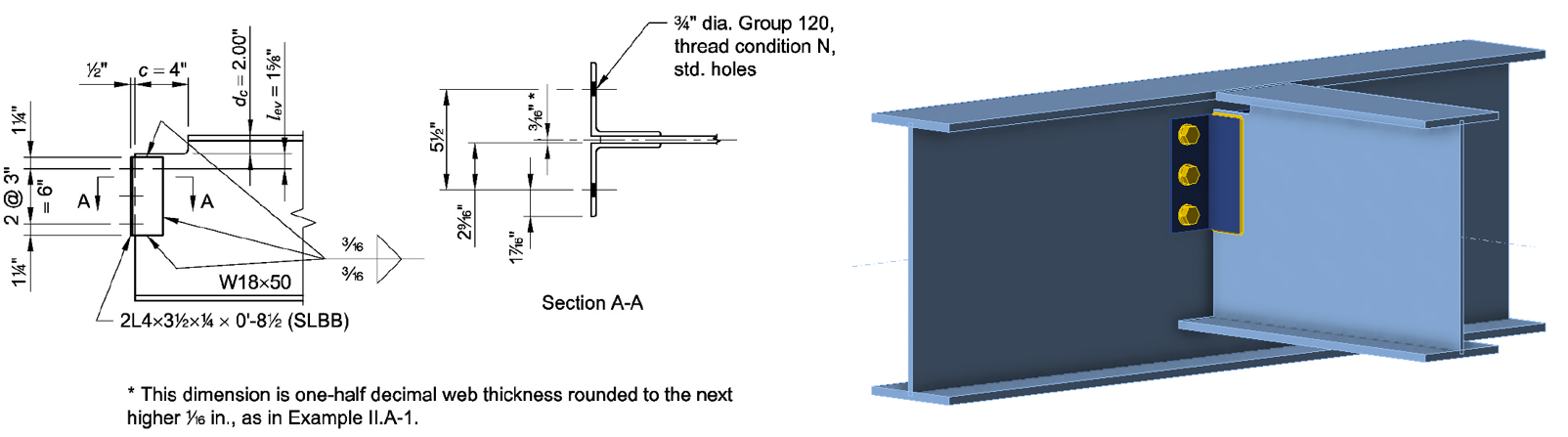
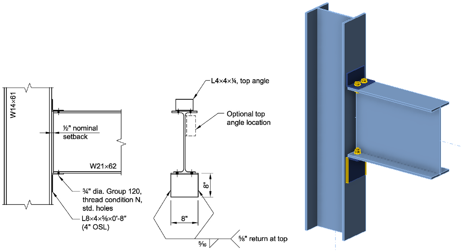
Connection 3 based on AISC Design Examples V16.0, Example II.A-5
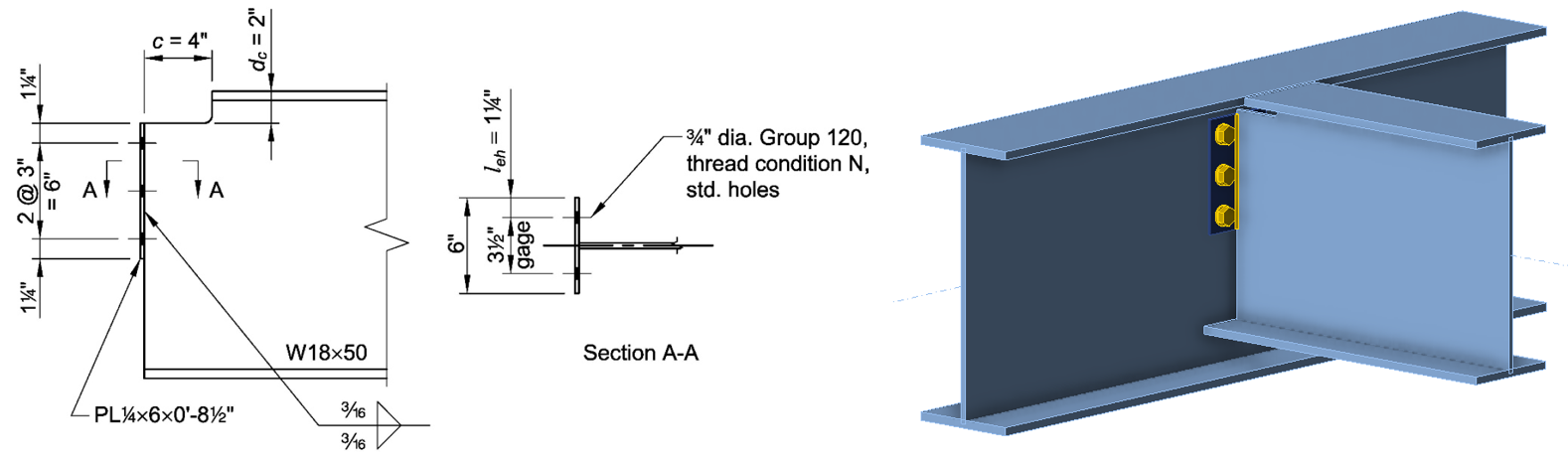
Connection 4 based on AISC Design Examples V16.0, Example II.A-11A
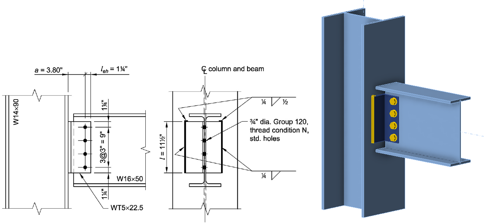
Connection 5 based on AISC Design Examples V16.0, Example II.A-13
Connection 6 based on AISC Design Examples V16.0, Example II.A-31
References
AISC. (2022). Specification for Structural Steel Buildings. American Institute of Steel Construction, Chicago, Illinois.
AISC. (2023a). Steel Construction Manual, 16th Edition. American Institute of Steel Construction, Chicago, Illinois.
AISC. (2023b). Companion to the AISC Steel Construction Manual, Volume 1: Design Examples, v16.0. American Institute of Steel Construction, Chicago, Illinois.
Tamboli, A. (Ed.). (2017). Handbook of Structural Steel Connection Design and Details, Third Edition. McGraw Hill, New York, NY.