
Anchoring plates options
Here is an overview of common stand-off scenarios, including mortar joint, nuts, and gaps. Further in the article, you can find an explanation of the Cut thread function, which, when used correctly, can help you achieve an accurate representation of hinged versus fixed anchor–plate behavior. The feature enhances physical accuracy without compromising calculation efficiency.
1. Base plate options
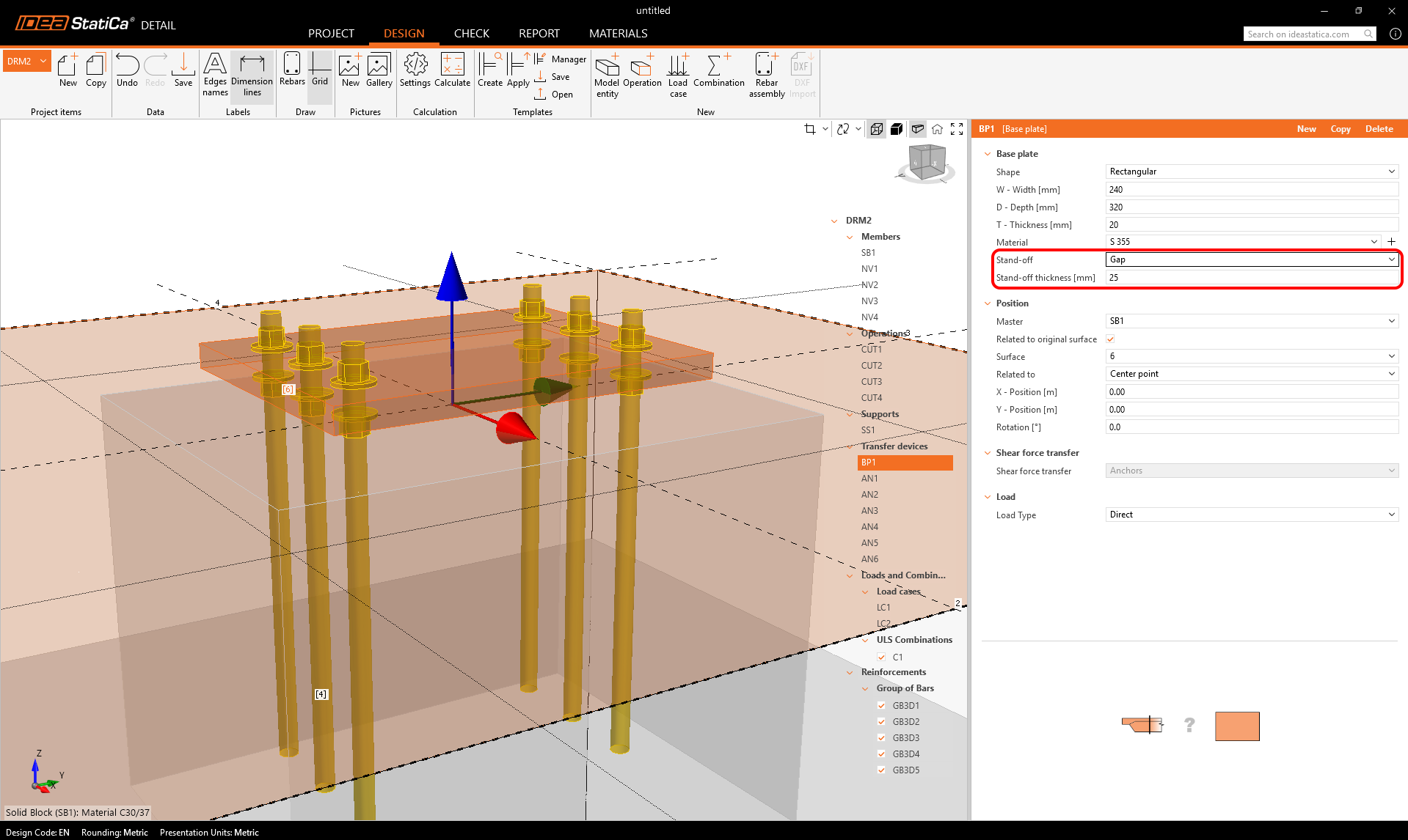
Stand-off
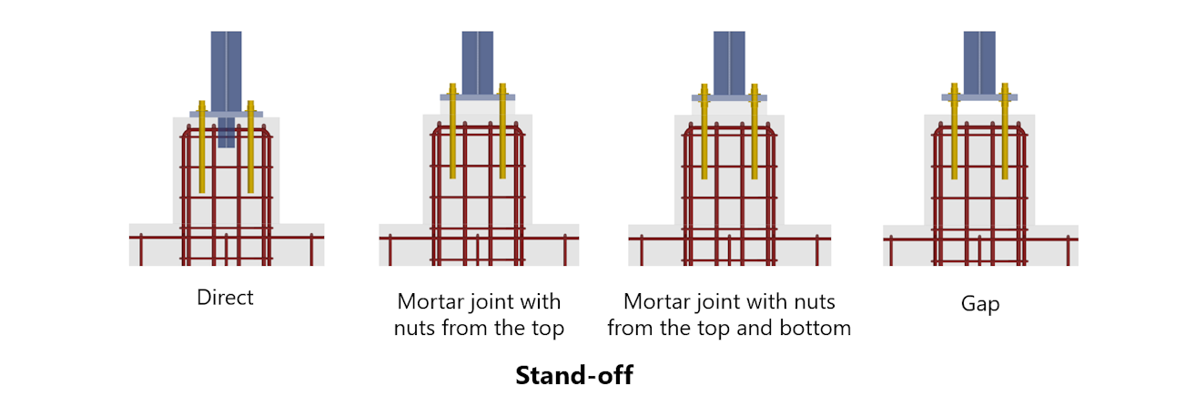
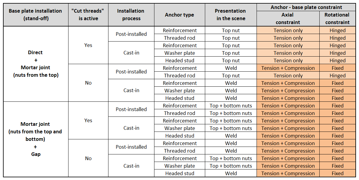
- Mortar joint – nuts from the top: a mortar layer can be defined with a specified thickness. The anchors are connected only from the top, modeling a hinged behavior.

- Mortar joint – nuts from the top and bottom: a mortar layer with nuts on both sides, allowing a fixed anchor–plate connection.

- Gap: a vertical clearance under the plate can be specified. Anchors are then directly loaded, with no contact between the plate and concrete.
Anchor types
Users can add an unlimited number of fasteners and even combine multiple types within a single plate. More information about anchor types (cast-in-place and post-installed) can be found in the Single anchor definition article.
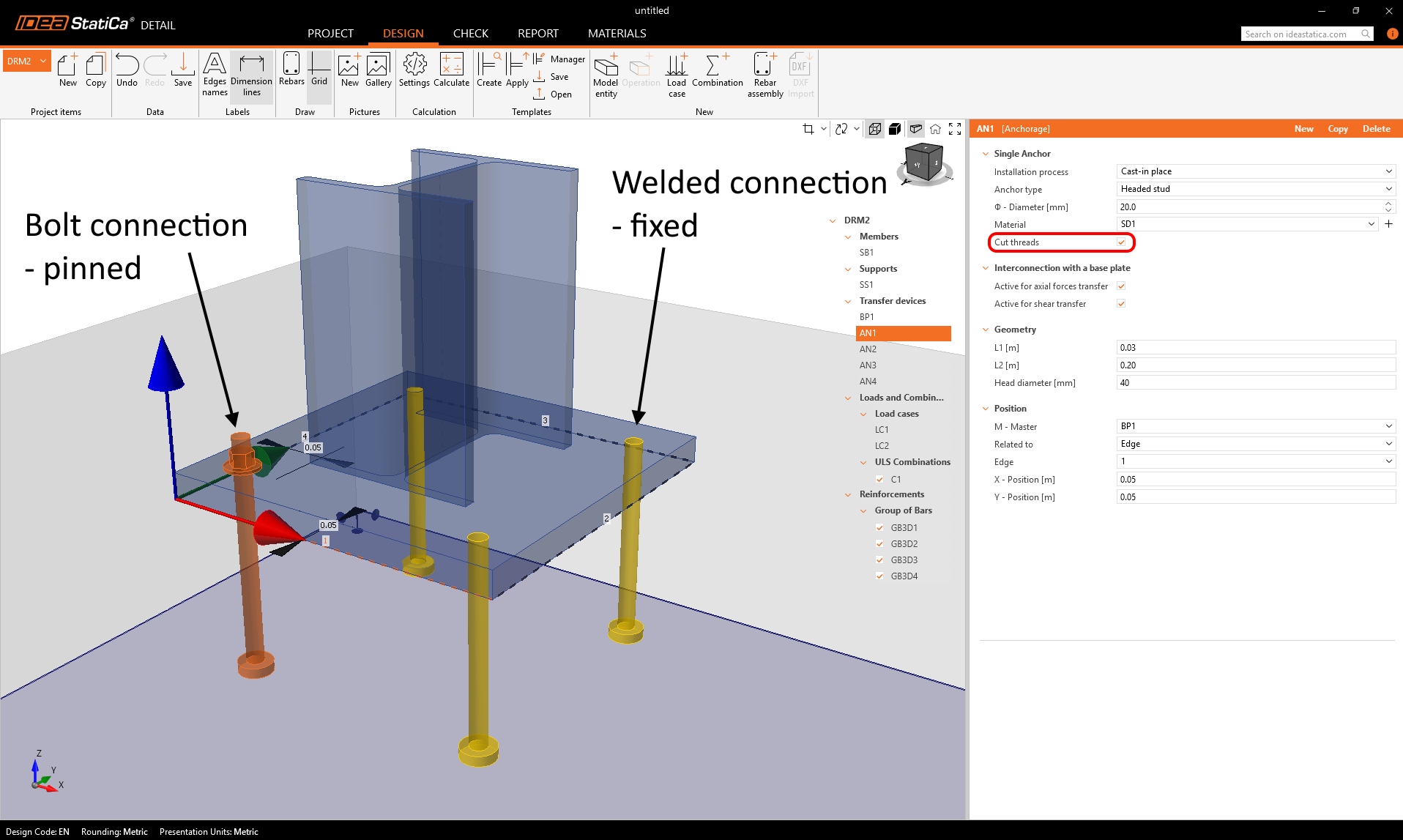
Cut thread option
The checkbox in the anchor properties lets you control how the anchor connects to the base plate and defines what behavior to expect from the steel-concrete connection.
- For headed studs and cast-in reinforcement connected to the base plate (not for Cast-in plates), it distinguishes between a bolt connection (pinned) and a welded connection (fixed) — visible in the 3D scene.
- The way of anchor-to-plate connection has a significant influence on the shear resistance from the point of view of the bearing of the concrete
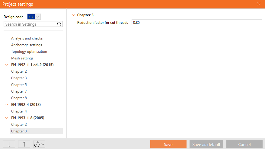
For EN, the resistance of the anchor with cut threads is reduced according to EN 1993-1-8 3.6.1 (3). It can be set in Project settings.
Technical notes
- The mortar layer is modeled as a shell element, with its stiffness taken into account, while it is incompressible. This helps to redistribute local forces to the concrete and is valid for typical bedding thicknesses used in practice - 25-50 mm.
- The distinction between nuts only from the top (pinned interconnection between anchor and base plate) vs. top and bottom (fixed interconnection between anchor and base plate) strongly influences the shear capacity from the point of view of concrete bearing.
Below is a summary table explaining axial and rotational constraints between the base plate and the anchor.
These stand-off settings are transferable when importing models from Connection.
Mortar joints and gaps are also available.
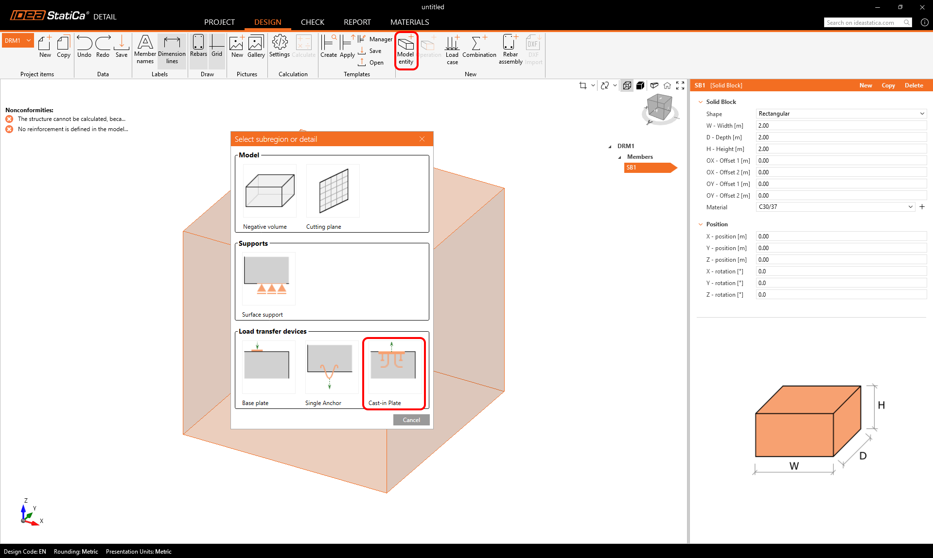
2. Cast-in plates options
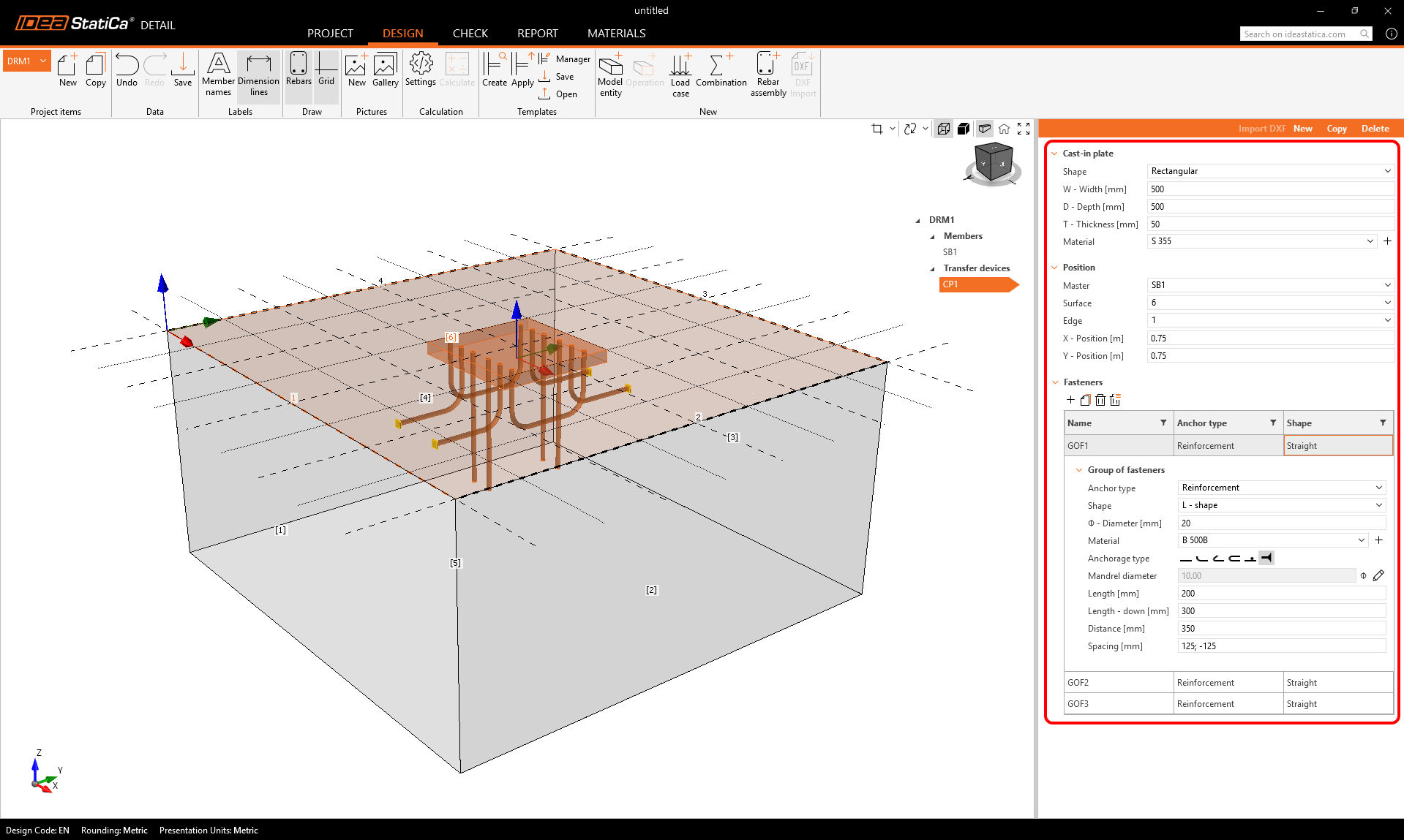
Cast-in plates are available as a Load Transfer Device in the model entity selection. The plate’s geometry and position can be defined in a single property grid, while an additional table allows users to add and combine multiple groups of fasteners.
Anchor types
Fasteners can be defined directly for each specific plate. Users can add an unlimited number of fasteners and even combine multiple types within a single plate. More information about the anchor types related to the Cast-in plate can be found in a separate article.
Model Behavior
Anchors are treated as elements resisting both shear and tension, as they are welded to the plate. Their evaluation follows the same principles as standard anchors. For more information, see the Theoretical Background.
Released in IDEA StatiCa version 25.1.