Extended moment end-plate connection – ASD
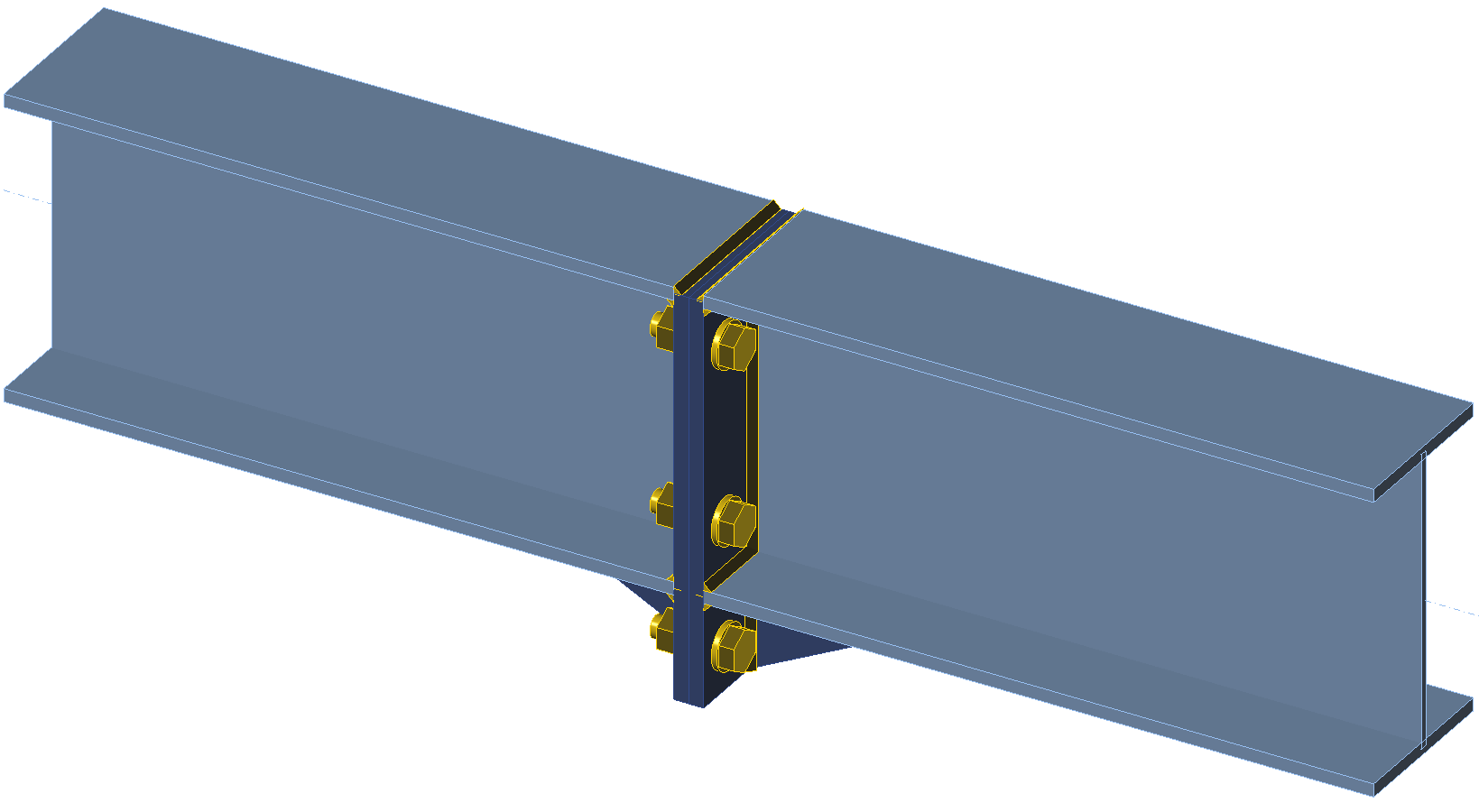
Two beams with cross-section W10\(\times\)26 are connected to each other by extended four-bolt stiffened moment end-plate connection. The end plates have the thickness of 1/2'' and are connected by 3 bolt rows. All steel is grade A572 Gr. 50 (fy = 50 ksi, fu = 65 ksi) and bolts are grade 3/4'' grade A325 (fyb =92 ksi, fub = 119.7 ksi). The connection is loaded by maximum bending moment determined from manual assessment using Design guide 16 and AISC 360-16.
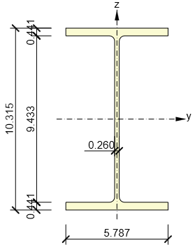
Beam cross-section
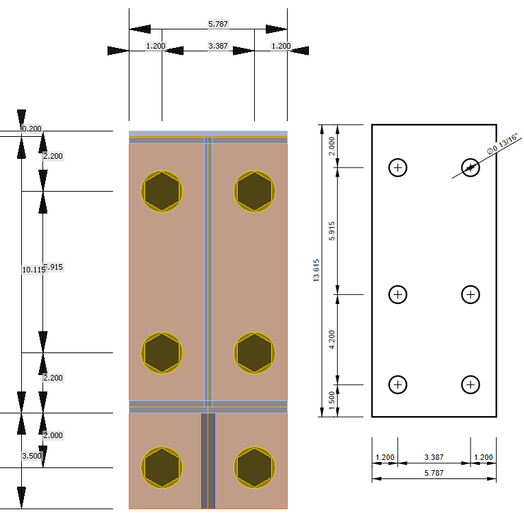
Dimensions of end-plate connection
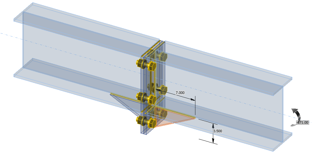
Transparent model with dimensions of widener and applied load
Manual assessment
Manual assessment is performed according to Design guide 16: Flush and Extended Multiple-Row Moment End-Plate Connections – Chapter 4: Extended End-Plate Design and AISC 360-16 – Chapter J. The following checks are required:
- Bolt strength in tension – AISC 360-16 – J3.6
- End-plate yielding – Design guide 16
- Weld strength – AISC 360-16 – J2.4
The design of beams is assumed to be checked elsewhere.
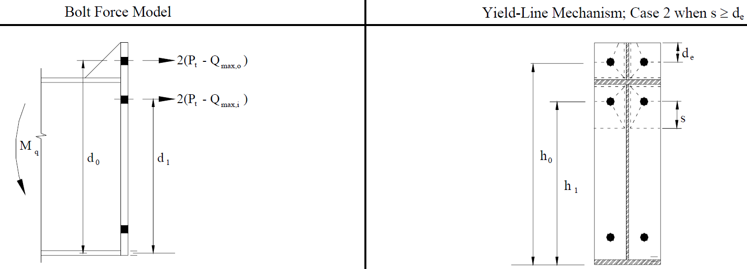
Bolt and end-plate yielding strength
Bolt tensile strength
\[A_b = \frac{\pi d_b^2}{4} = \frac{\pi \cdot 0.75^2}{4} = 0.442 \,\textrm{in}^2 \]
\[P_t = R_n = F_n A_b = 90 \cdot 0.442 = 39.8 \,\textrm{kip}\]
Snug-tightened bolt pretension:
\[T_b = 0.5 \cdot 28 = 14 \,\textrm{kip}\]
Prying forces
The prying forces are determined according to Design guide 16 – Table 4-1:
Inside bolt row:
\[a_i = 3.682 \left ( \frac{t_p}{d_b} \right )^3 - 0.085 = 3.682 \left( \frac{0.5}{0.75} \right)^3 - 0.085 = 1.006 \]
\[w' = b_p / 2 - (d_b + 1/16) = 5.787 / 2 - (0.75 + 1/16) = 2.081 \,\textrm{in} \]
\[F'_i = \frac{t_p^2 F_{py} \left ( 0.85 \frac{b_p}{2} + 0.80 w' \right ) + \frac{\pi d_b^3 F_t}{8}}{4 p_{f,i}} \]
\[F'_i = \frac{0.5^2 \cdot 50 \left ( 0.85 \cdot \frac{5.787}{2} + 0.80 \cdot 2.081 \right ) + \frac{\pi \cdot 0.75^3 \cdot 90}{8}}{4 \cdot 1.759} = 9.446 \]
\[Q_{max,i}= \frac{w' t_p^2}{4 a_i} \sqrt{F_{py}^2 -3 \left( \frac{F'_i}{w' t_p} \right)^2 } \]
\[Q_{max,i}= \frac{2.081 \cdot 0.5^2}{4 \cdot 1.006} \sqrt{50^2 -3 \cdot \left( \frac{9.446}{2.081 \cdot 0.5} \right)^2 } = 6.137 \,\textrm{kip}\]
Outside bolt row:
\[a_o = 3.682 \left ( \frac{t_p}{d_b} \right )^3 - 0.085 = 3.682 \left( \frac{0.5}{0.75} \right)^3 - 0.085 = 1.006 \]
\[w' = b_p / 2 - (d_b + 1/16) = 5.787 / 2 - (0.75 + 1/16) = 2.081 \,\textrm{in} \]
\[F'_o = \frac{t_p^2 F_{py} \left ( 0.85 \frac{b_p}{2} + 0.80 w' \right ) + \frac{\pi d_b^3 F_t}{8}}{4 p_{f,o}} \]
\[F'_o = \frac{0.5^2 \cdot 50 \left ( 0.85 \cdot \frac{5.787}{2} + 0.80 \cdot 2.081 \right ) + \frac{\pi \cdot 0.75^3 \cdot 90}{8}}{4 \cdot 2} = 8.308 \]
\[Q_{max,i}= \frac{w' t_p^2}{4 a_o} \sqrt{F_{py}^2 -3 \left( \frac{F'_o}{w' t_p} \right)^2 } \]
\[Q_{max,i}= \frac{2.081 \cdot 0.5^2}{4 \cdot 1.006} \sqrt{50^2 -3 \cdot \left( \frac{8.308}{2.081 \cdot 0.5} \right)^2 } = 6.212 \,\textrm{kip}\]
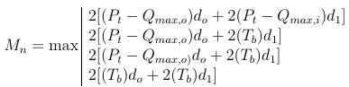
End-plate yielding
\[s=\frac{1}{2} \sqrt{b_p g} = \frac{1}{2} \sqrt{5.787 \cdot 3.387} = 2.214 \,\textrm{in}\]
Dimension s is larger than dimension de, therefore case 2 applies.
End-plate yield mechanism (Design guide 16)
\[Y = \frac{b_p}{2} \left[ h_1 \left( \frac{1}{p_{f,i}} + \frac{1}{s} \right) + h_o \left( \frac{1}{p_{f,o}} + \frac{1}{2s} \right) \right] + \frac{2}{g} [h_1 (p_{f,i}+s) + h_o (d_e + p_{f,o})]\]
\[Y = \frac{5.787}{2} \left[ 8.115 \left( \frac{1}{1.759} + \frac{1}{2.214} \right) + 12.315 \left( \frac{1}{2} + \frac{1}{2\cdot 2.214} \right) \right] + \frac{2}{3.387} [8.115 (1.759+2.214) + 12.315 (1.5 + 2)] = 94.310 \,\textrm{in}\]
\[\frac{M_n}{\Omega} = \frac{M_{pl}}{\Omega} = \frac{F_{py} t_p^2 Y}{\Omega} = \frac{50 0.5^2 \cdot 94.310}{1.67} = 705.911\,\textrm{kip-in}\]
Bolt rupture with prying action
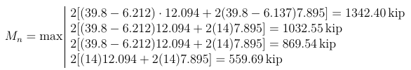
\[\frac{M_n}{\Omega} =\frac{1342.4}{2} = 671.198 \,\textrm{kip}\]
Bolt rupture without prying action
\[\frac{M_n}{\Omega} =\frac{2P_t(d_o+d_1)}{\Omega}\frac{2\cdot 39.8 \cdot (12.095+7.895)}{2} = 795.602 \,\textrm{kip}\]
The decisive failure mode is the one with smallest strength, i.e. bolt rupture with prying action, \(\frac{M_n}{\Omega}=671.198 \,\textrm{kip}\).
Weld strength
In manual assessment, it is assumed that effective weld transferring bending moment is a cruciform consisting of the weld of the stiffener to the end-plate extension (l = 3.5 in, w = 1/4''), weld of the flange to the end-plate (l = 5.787 in, w = 1/4''), and weld of the estimated effective part of the web to the end-plate (l = 3.5 in, w= 1/4''). The center of gravity of such cruciform is conveniently at the beam flange, thus the lever arm is 9.874 in. The weld cruciform needs to transfer force Mu/9.874= 671/9.874 = 68 kip.
\[A_{we} = 1/4 \cdot 2\cdot (3.5+5.787+3.5) / \sqrt(2)=4.52\,\textrm{in}^2 \]
\[F_{nw} = 0.6 F_{EXX} (1+0.5 \sin^{1.5} \theta) = 0.6 \cdot 70 \cdot (1+0.5 \sin^{1.5} 40^\circ) = 53 \,\textrm{ksi} \]
\[R_n/\Omega = F_{nw} A_{we} / \Omega = 53 \cdot 4.52 / 2= 119.78 \,\textrm{kip}\]
The weld strength is sufficient.
The weld strength of compressed welds is not checked here, because it is expected that the loads are transferred by direct contact.
Check in IDEA StatiCa
In IDEA StatiCa Connection, all prying forces and yield lines are determined automatically by finite element analysis. The bolt forces are shown with included prying forces. The point of rotation is also calculated automatically and requires no educated guess. All welds are checked and no force transfer by contact is assumed. The workaround would be setting of contact or butt weld instead of fillet weld.
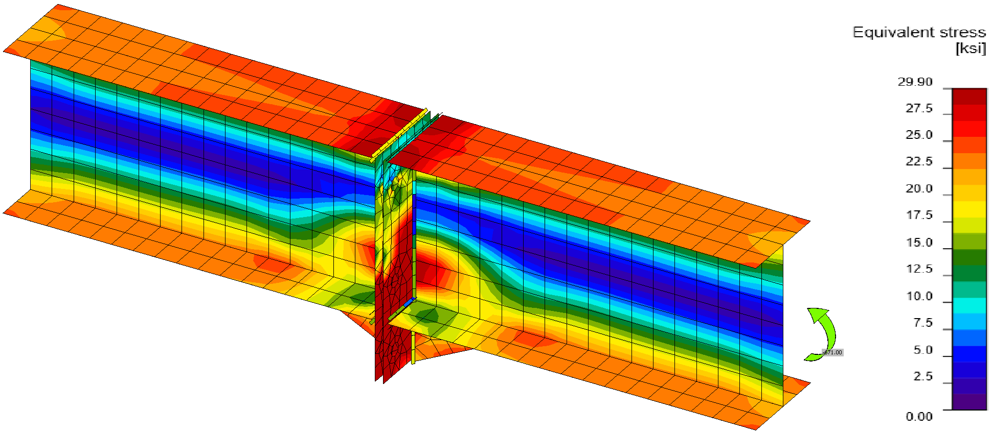
Von Mises stress
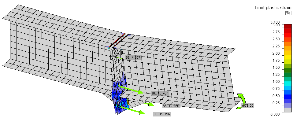
Plastic strain, applied load, and bolt forces on a deformed model (scale 10\(\times\))
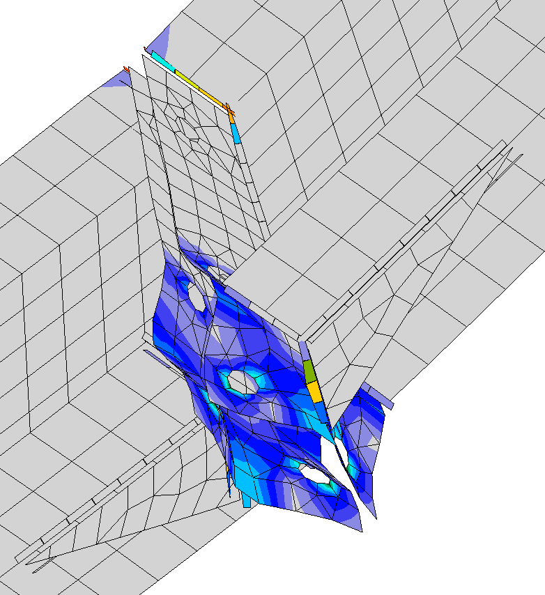
Detail of end plate deformation (scale 20\(\times\))
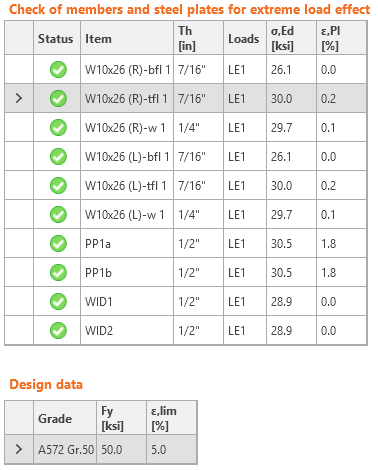
Check of stress and strain in plates
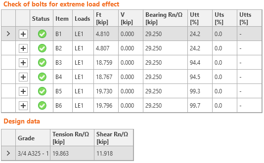
Check of bolts
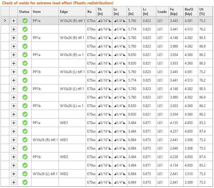
Check of welds
The stiffness can also be easily evaluated in IDEA StatiCa Connection. This connection is close to the boundary of rigid and semi-rigid. The boundary depends on the length of connected beam.
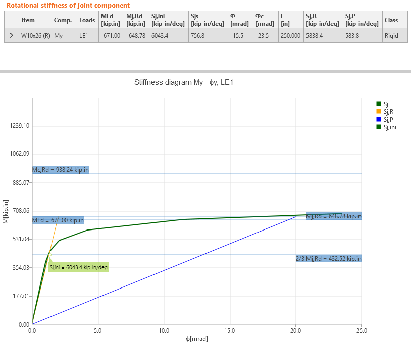
Stiffness of the joint
Comparison
IDEA StatiCa Connection provides the same results as the manual assessment. Bolts are utilized at 99.7 %, the plates of the end-plates are yielding, the plastic strain is 1.8 %, which means that the failure mode of end-plate yielding is close. The deformed shape coincides with the assumed deformation in Design Guide 16. The utilization at 100 % is at bending moment 673 kip-in (0.3 % difference).
Attached Downloads
- AISC.pdf (PDF, 1.2 MB)