Description
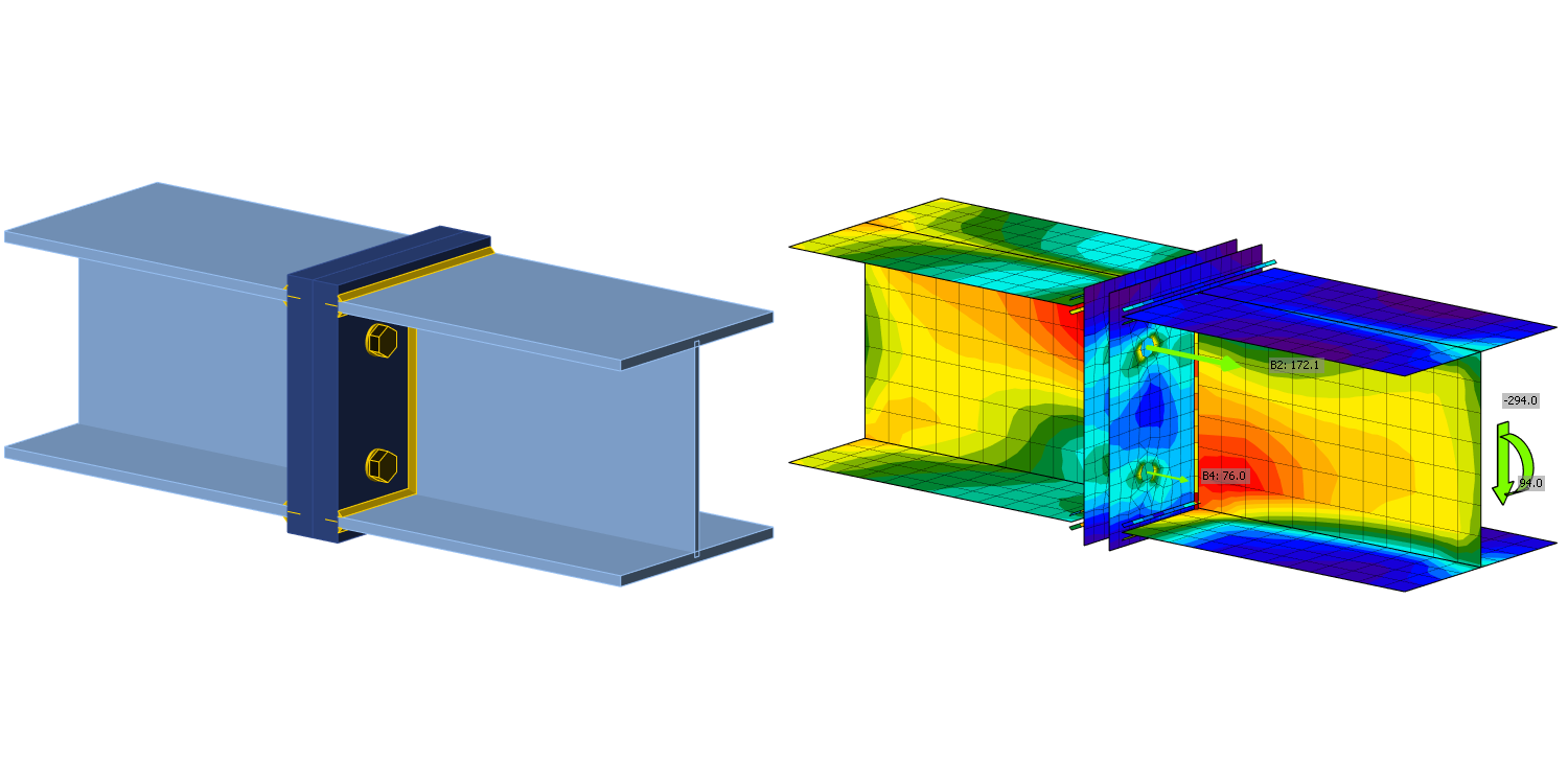
The objective of this chapter is a verification of the component-based finite element method (CBFEM) for the interaction of shear and tension in a bolt to an analytical model (AM). A beam-to-beam joint with end plates and two rows of bolts was selected for verification; see Fig. 5.5.1. The bending stiffness of the joint is high enough to be classified as rigid.
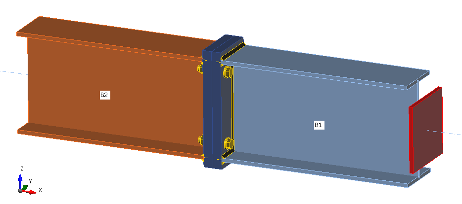
\[ \textsf{\textit{\footnotesize{Fig. 5.5.1 Joint arrangement of bolted beam-to-beam joint}}}\]
Analytical model
Bolt resistance in interaction of shear and tension is designed according to Tab. 3.4 in chapter 3.6.1 in EN 1993-1-8:2005. A bilinear relation is used. The geometry and the end plate dimensions of the joint are selected to limit the design resistance of the joint by bolt failure. The design resistance of equivalent T-stub in tension is modeled according to Tab. 6.2 in chapter 6.2.4 in EN 1993‑1‑8:2005.
Verification of resistance
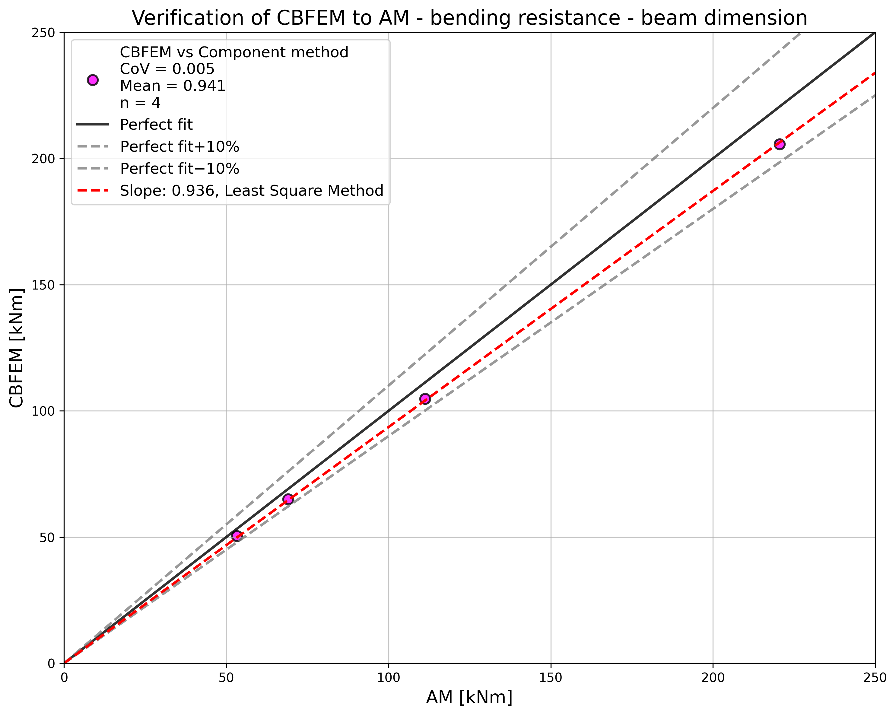
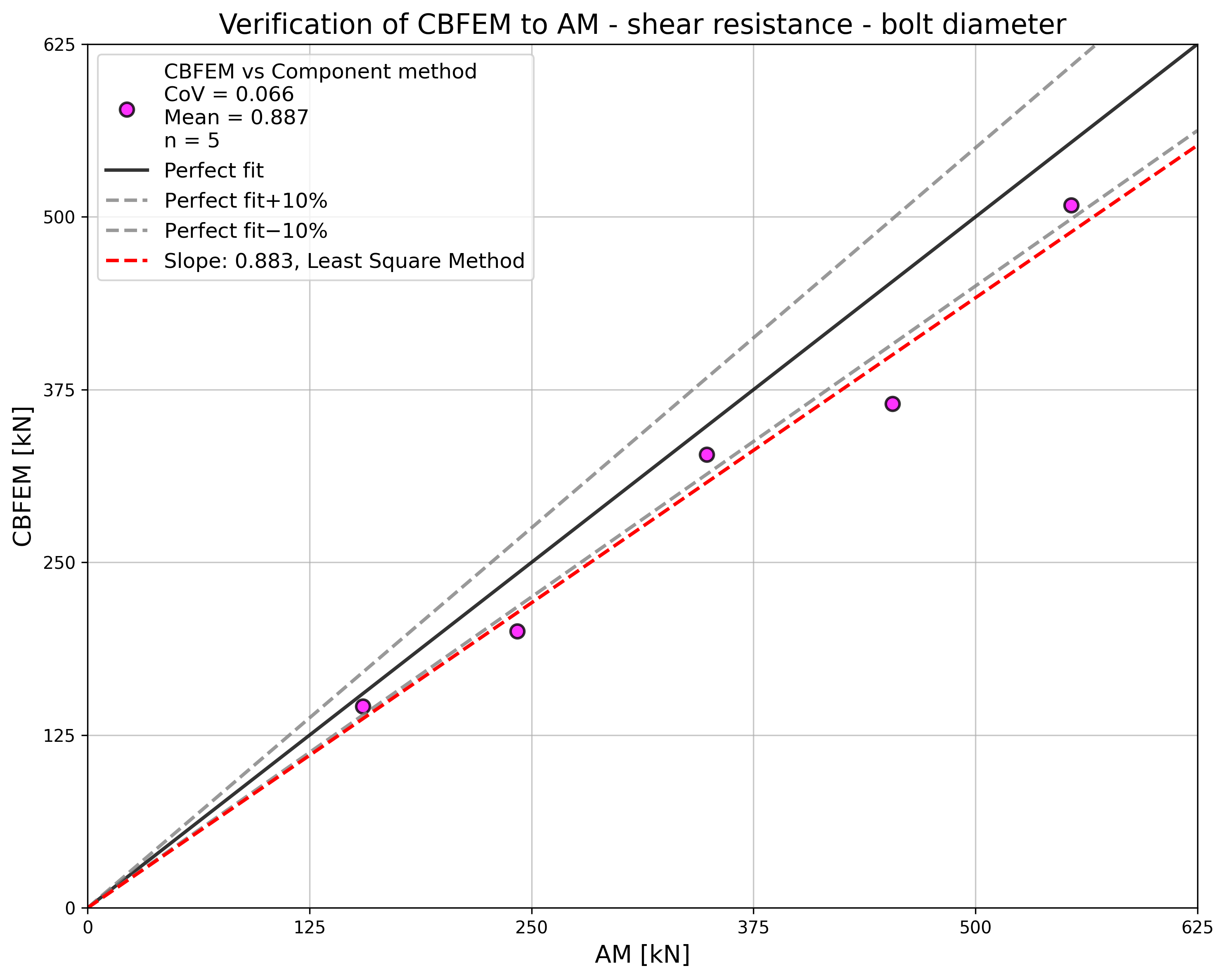
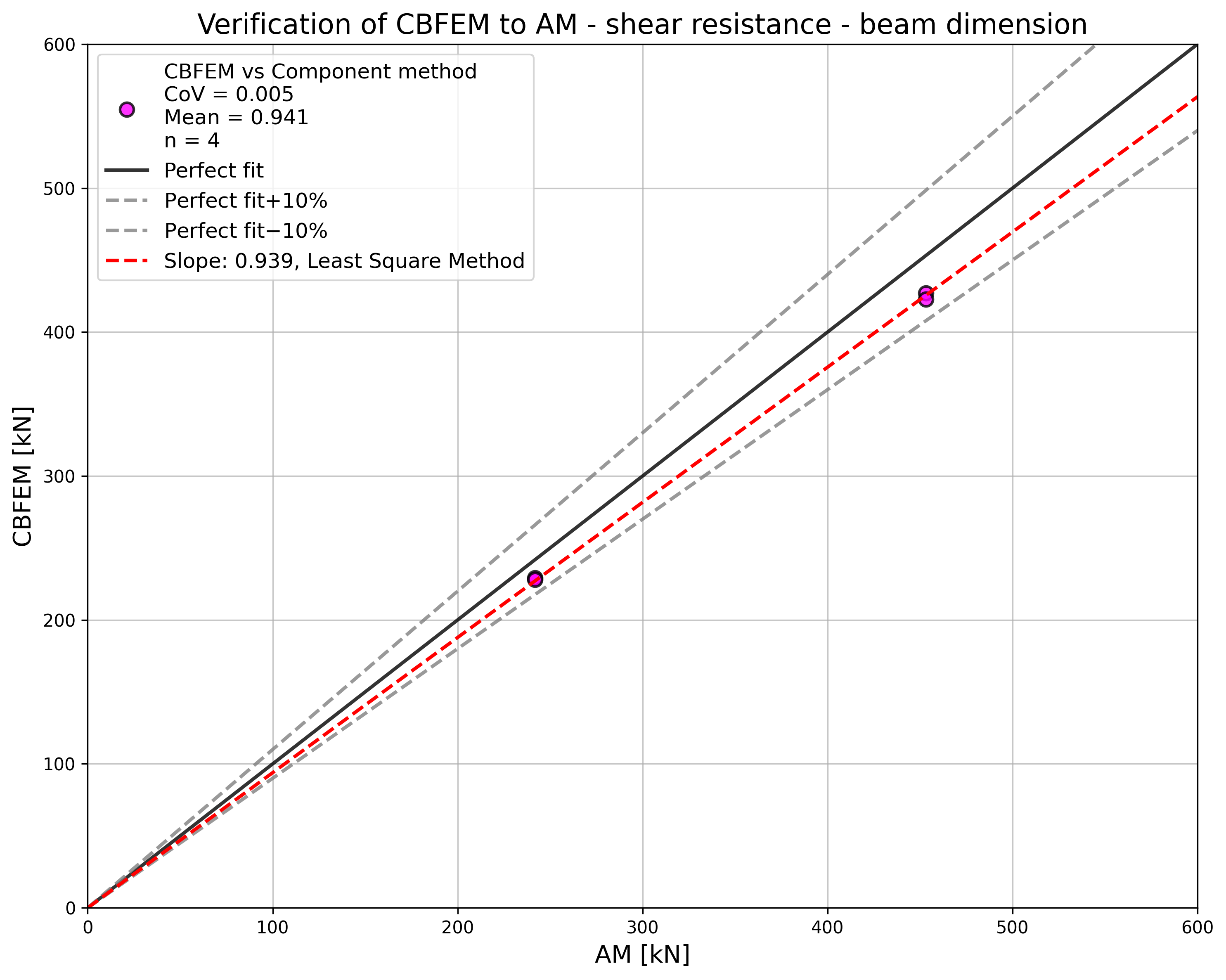
Parameters of the model are a bolt diameter and a beam dimension; see Figs 5.5.2 to 5.5.5. Dimensions of the end plate and the bolt distances are modified to limit the joint resistance by the bolt failure. The shear and bending resistance of the joint is compared in loading at the bolt failure. The results are summarised in Tab. 5.5.1 and 5.5.2.
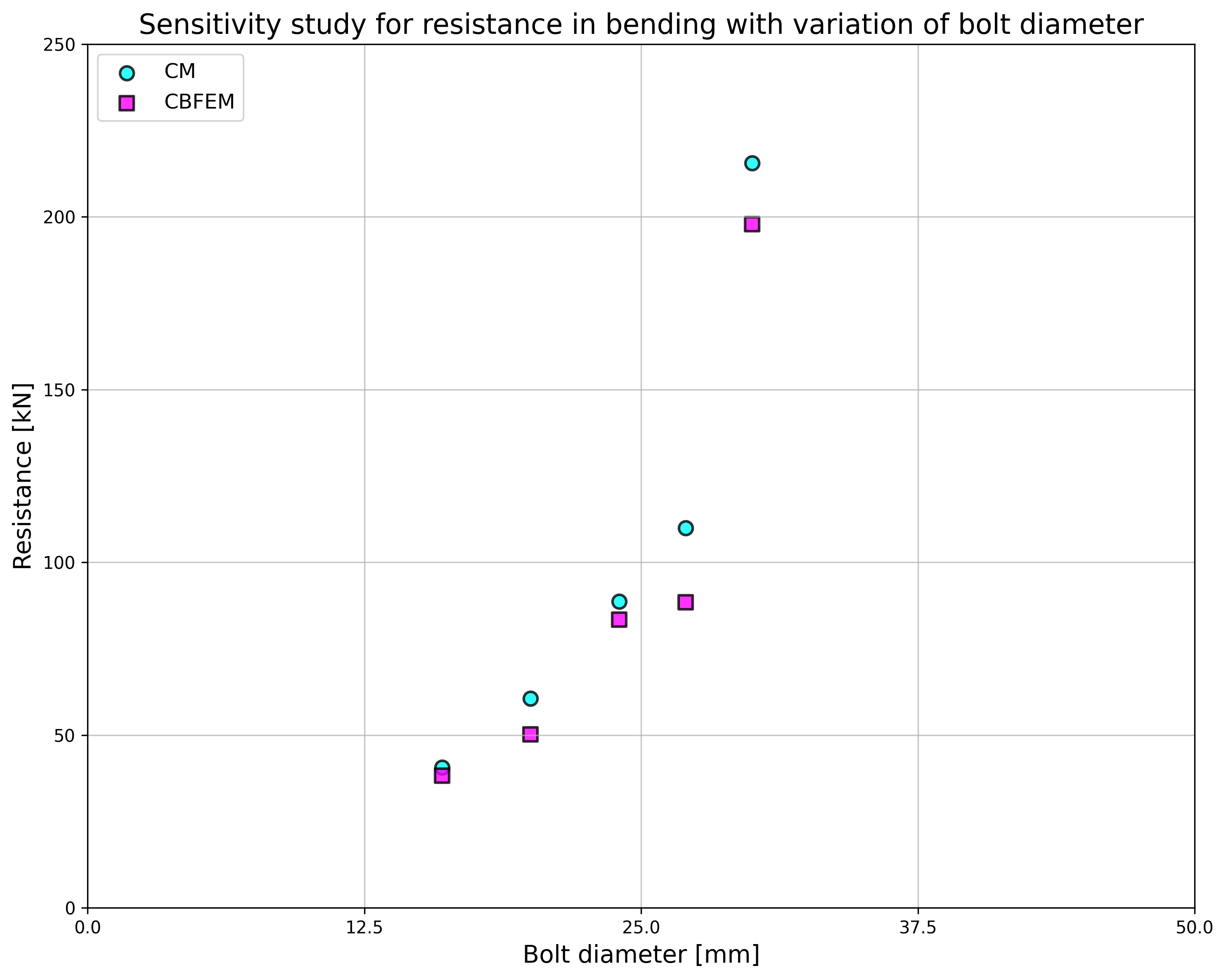
\[ \textsf{\textit{\footnotesize{Fig. 5.5.2 Sensitivity study for resistance in bending with variation of bolt diameter}}}\]
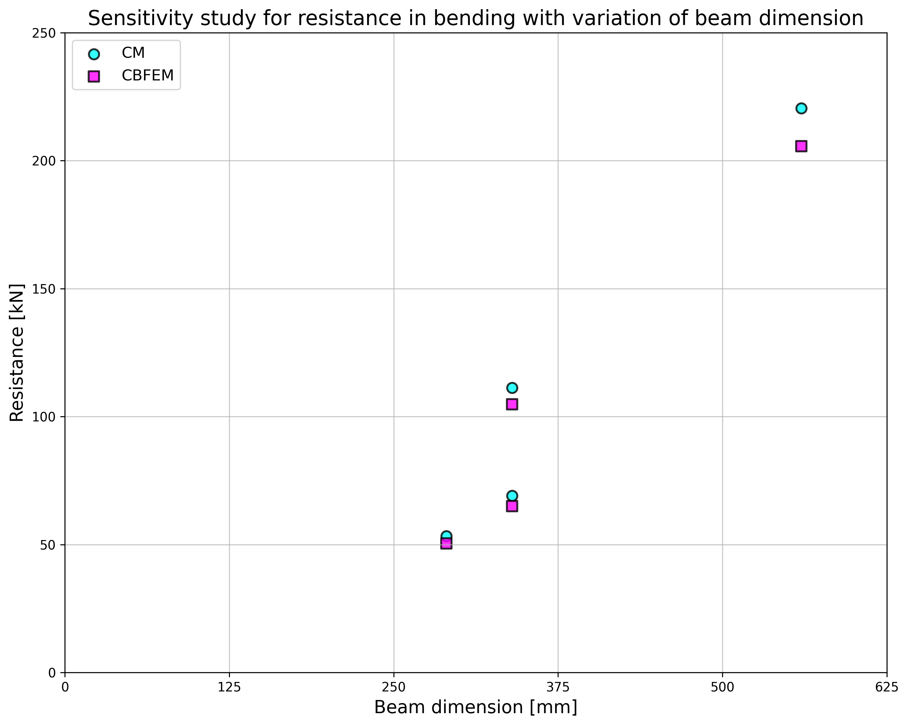
\[ \textsf{\textit{\footnotesize{Fig. 5.5.3 Sensitivity study for resistance in bending with variation of beam dimension}}}\]
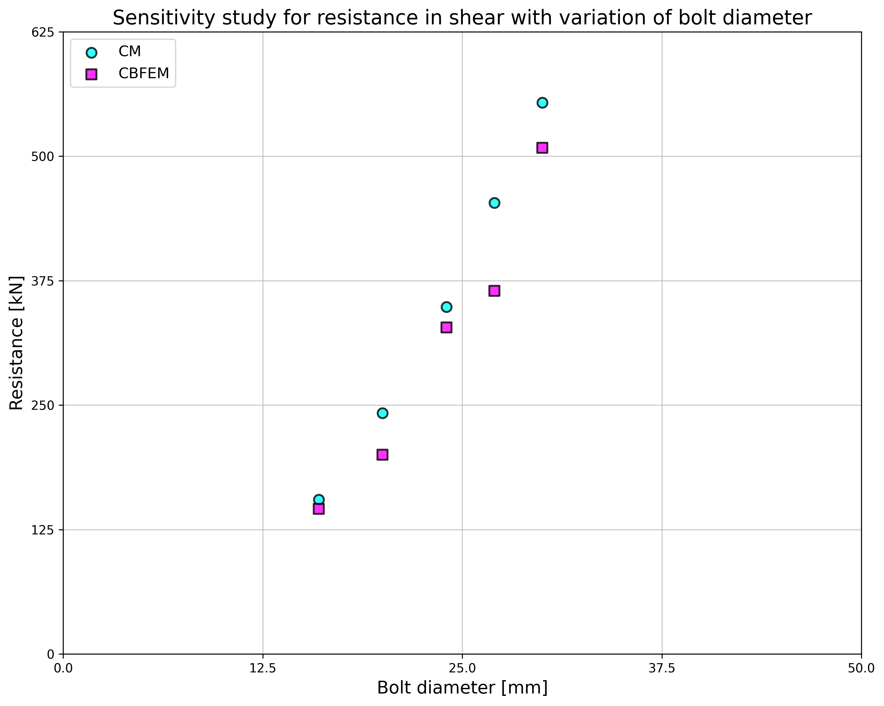
\[ \textsf{\textit{\footnotesize{Fig. 5.5.4 Sensitivity study for resistance in shear with variation of bolt diameter}}}\]
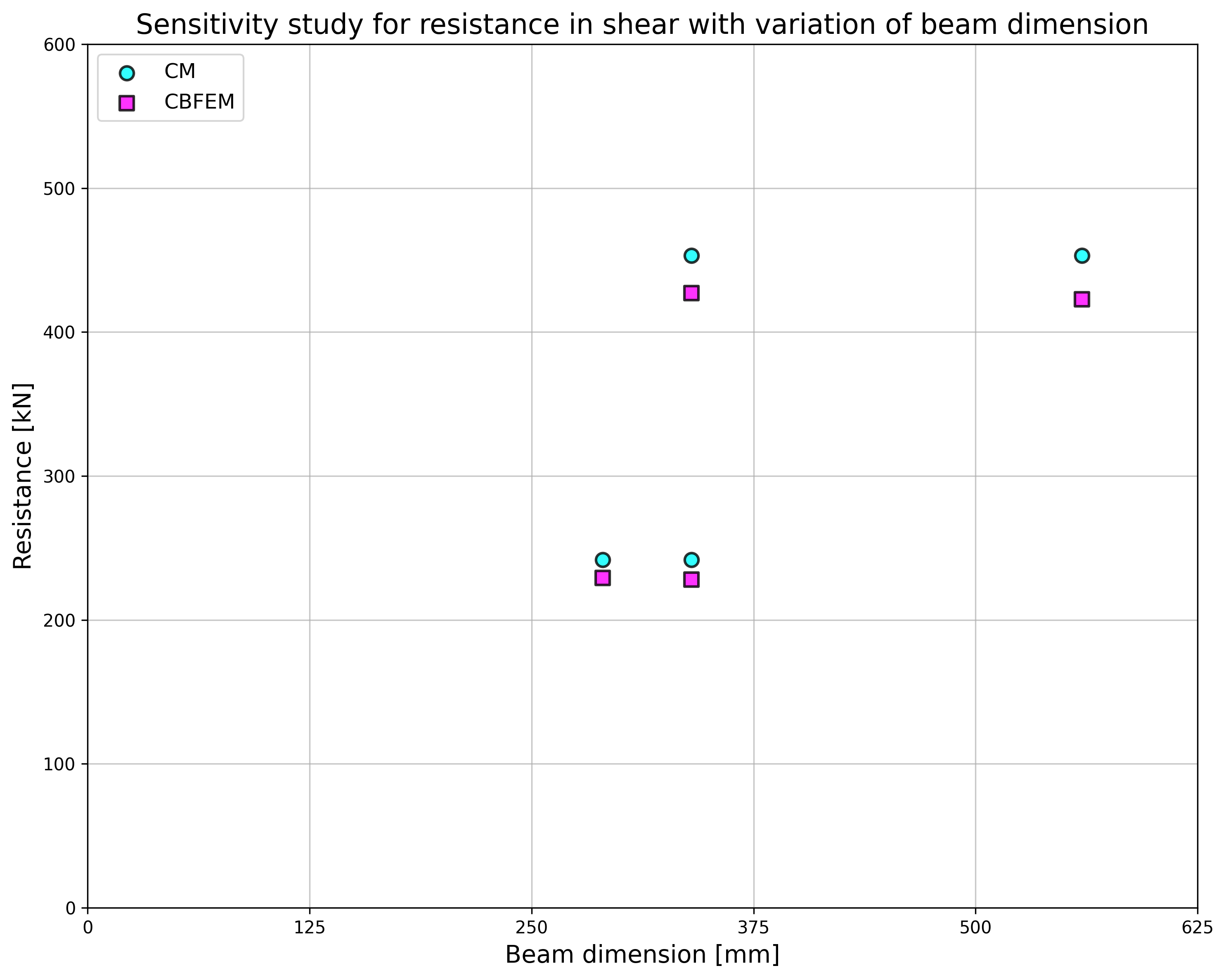
\[ \textsf{\textit{\footnotesize{Fig. 5.5.5 Sensitivity study for resistance in shear with variation of beam dimension}}}\]
Tab. 5.5.1 Sensitivity study for resistance with variation of bolt diameter
| Parameter | AM | CBFEM | AM/CBFEM | |||||
| Beam; end plate | Diameter | Distances | MRd [kNm] | VRd [kN] | MRd [kNm] | VRd [kN] | MRd | VRd |
| IPE270; tp = 30mm; 150×310mm | M16/8.8 | e1 = 60 mm; p1 = 190 mm; w = 90 mm | 41 | 155 | 38 | 146 | 1,06 | 1,06 |
| M20/8.8 | e1 = 70 mm; p1 = 170 mm; w = 90 mm | 61 | 242 | 50 | 200 | 1,21 | 1,21 | |
| HEA300; tp = 40mm; 300×330mm | M24/8.8 | e1 = 85 mm; p1 = 160 mm; w = 150 mm | 89 | 349 | 83 | 328 | 1,06 | 1,06 |
| M27/8.8 | e1 = 95 mm; p1 = 140 mm; w = 150 mm | 110 | 453 | 89 | 365 | 1,24 | 1,24 | |
| HEA500; tp = 40mm; 330×520mm | M30/8.8 | e1 = 160 mm; p1 = 200 mm; w = 150 mm | 216 | 554 | 198 | 509 | 1,09 | 1,09 |
Tab. 5.5.2 Sensitivity study for resistance with variation of the beam dimension
| Parameter | AM | AM | CBFEM | CBFEM | AM/CBFEM | AM/CBFEM | ||
| Beam; fin plate | Diameter | Distances | MRd [kNm] | VRd [kN] | MRd [kNm] | VRd [kN] | MRd | VRd |
| HEA260; tp = 25mm; 260×290mm | M20/8.8 | e1 = 75 mm; p1 = 140 mm; w = 130 mm | 53 | 242 | 50 | 229 | 1,06 | 1,06 |
| IPE300; tp = 30mm; 150×340mm | M20/8.8 | e1 = 70 mm; p1 = 200 mm; w = 90 mm | 69 | 242 | 65 | 228 | 1,06 | 1,06 |
| HEB300; tp = 40mm; 300×340mm | M27/8.8 | e1 = 100 mm; p1 = 140 mm; w = 150 mm | 111 | 453 | 105 | 427 | 1,06 | 1,06 |
| IPE500; tp = 45mm; 220×560mm | M27/8.8 | e1 = 105 mm; p1 = 350 mm; w = 120 mm | 220 | 453 | 206 | 423 | 1,07 | 1,07 |
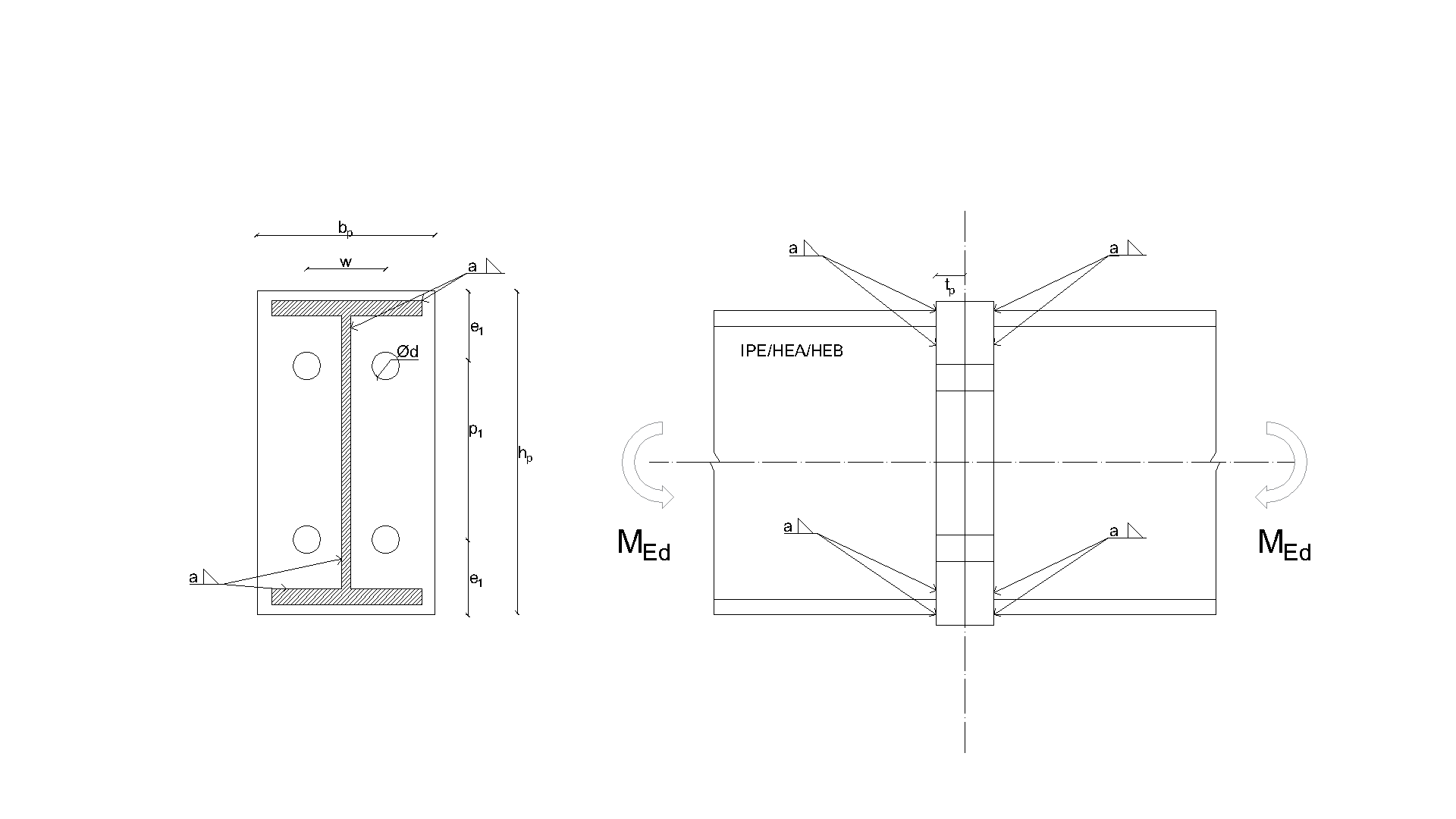
\[ \textsf{\textit{\footnotesize{Drawing 5.5.1 Joint geometry and dimensions}}}\]
The results of sensitivity studies are summarized in graphs in Fig. 5.5.6 and 5.5.7. The results show that the differences between the two calculation methods are below 10 %. The analytical model gives generally higher resistance.
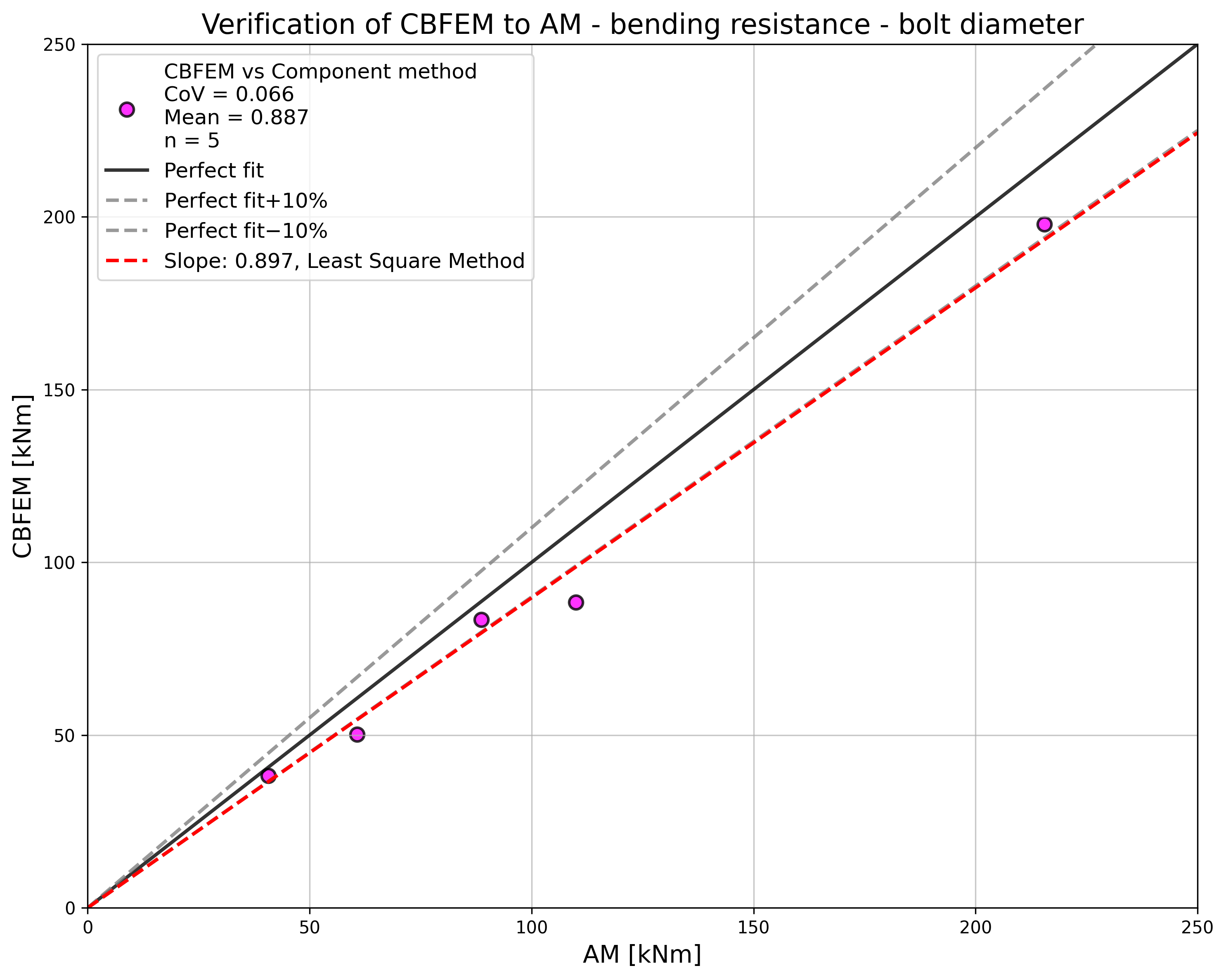
\[ \textsf{\textit{\footnotesize{Fig. 5.5.6 Verification of CBFEM to AM for the interaction of shear and tension in bolt in case of loading to bending resistance of a joint}}}\]
\[ \textsf{\textit{\footnotesize{Fig. 5.5.7 Verification of CBFEM to AM for the interaction of shear and tension in bolt in case of loading to shear resistance of a joint}}}\]
Benchmark example
Inputs
Connected members
- Steel S355
- Beams HEA300
- End plate thickness tp = 40 mm
- End plate dimensions 300 × 330 mm
Bolts
- 4 × M24 8.8
- Distances e1 = 85 mm; p1 = 160 mm; w1 = 75 mm; w = 150 mm
Outputs
- Design resistance in bending MRd = 93 kNm
- Design resistance in shear VRd = 291 kN
- Collapse mode is bolt failure in interaction of shear and tension