Šroubový přípoj - Interakce smyku a tahu
Popis
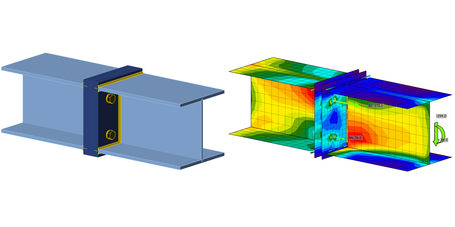
Cílem této kapitoly je ověření metody konečných prvků založené na komponentách (CBFEM) pro interakci smyku a tahu ve šroubu s analytickým modelem (AM). Pro ověření byl vybrán přípoj nosník-nosník s čelními deskami a dvěma řadami šroubů; viz obr. 5.5.1. Ohybová tuhost přípoje je dostatečně vysoká, aby byl klasifikován jako tuhý.
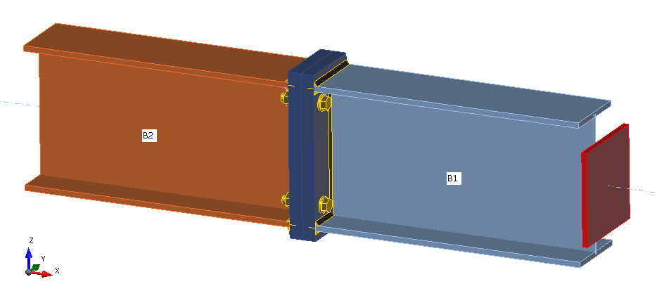
\[ \textsf{\textit{\footnotesize{Fig. 5.5.1 Joint arrangement of bolted beam-to-beam joint}}}\]
Analytický model
Únosnost šroubu při interakci smyku a tahu je navržena podle Tab. 3.4 v kapitole 3.6.1 normy EN 1993-1-8:2005. Je použit bilineární vztah. Geometrie a rozměry čelní desky přípoje jsou zvoleny tak, aby návrhová únosnost přípoje byla omezena porušením šroubu. Návrhová únosnost ekvivalentního T-průřezu v tahu je modelována podle Tab. 6.2 v kapitole 6.2.4 normy EN 1993‑1‑8:2005.
Ověření únosnosti
Parametry modelu jsou průměr šroubu a rozměr nosníku; viz obr. 5.5.2 až 5.5.5. Rozměry čelní desky a vzdálenosti šroubů jsou upraveny tak, aby byla únosnost přípoje omezena porušením šroubu. Únosnost přípoje ve smyku a ohybu je porovnána při zatížení odpovídajícím porušení šroubu. Výsledky jsou shrnuty v Tab. 5.5.1 a 5.5.2.
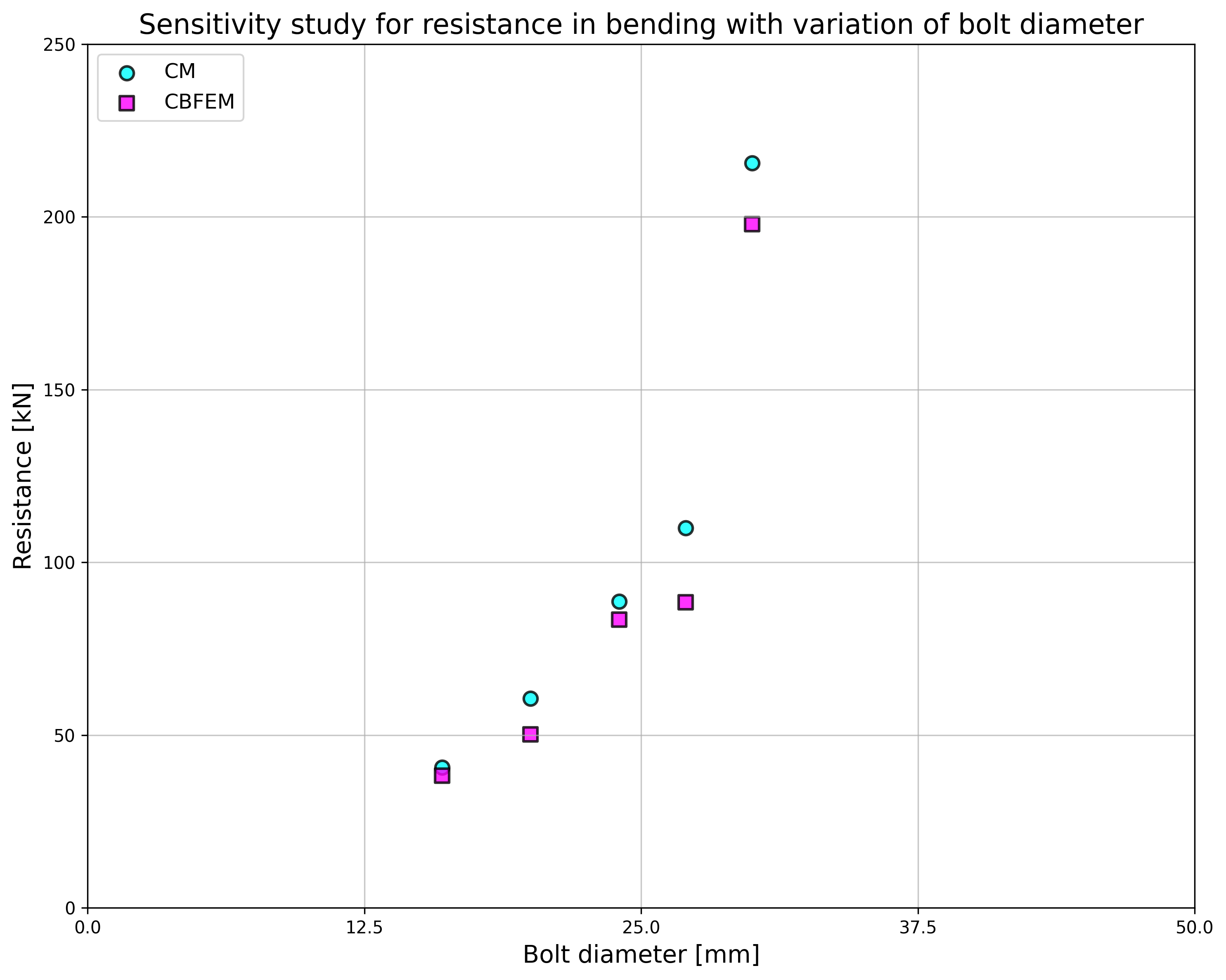
\[ \textsf{\textit{\footnotesize{Fig. 5.5.2 Sensitivity study for resistance in bending with variation of bolt diameter}}}\]
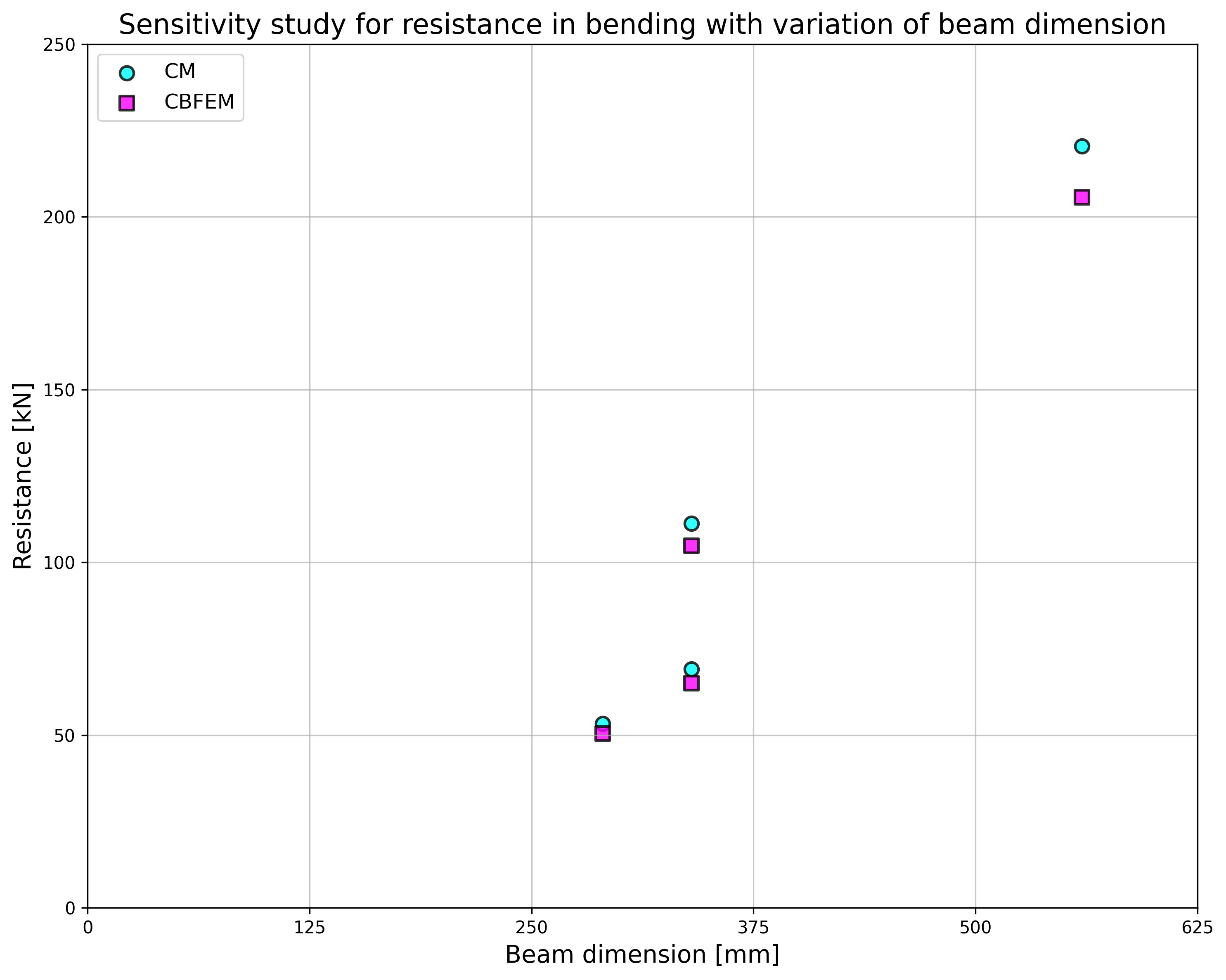
\[ \textsf{\textit{\footnotesize{Fig. 5.5.3 Sensitivity study for resistance in bending with variation of beam dimension}}}\]
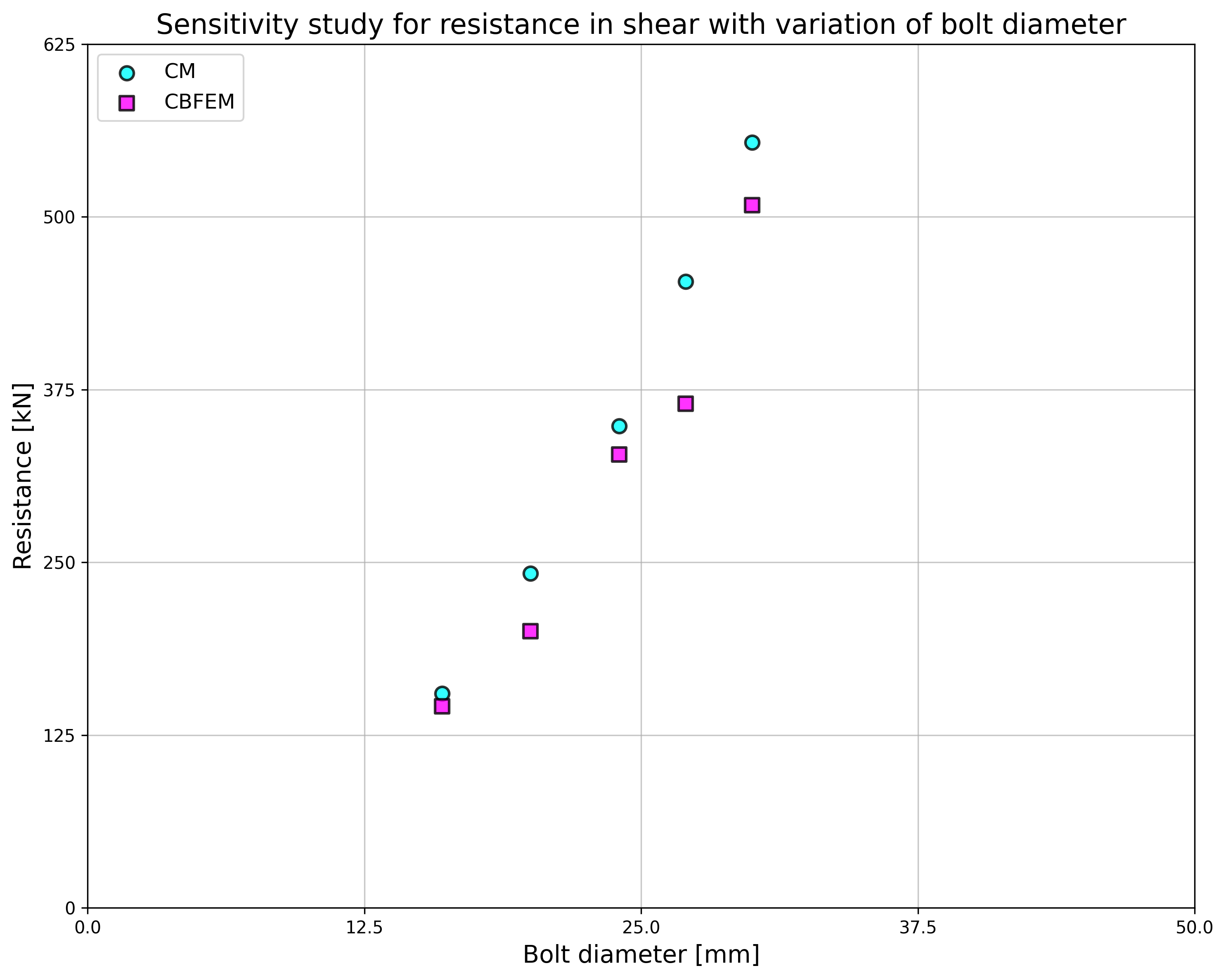
\[ \textsf{\textit{\footnotesize{Fig. 5.5.4 Sensitivity study for resistance in shear with variation of bolt diameter}}}\]
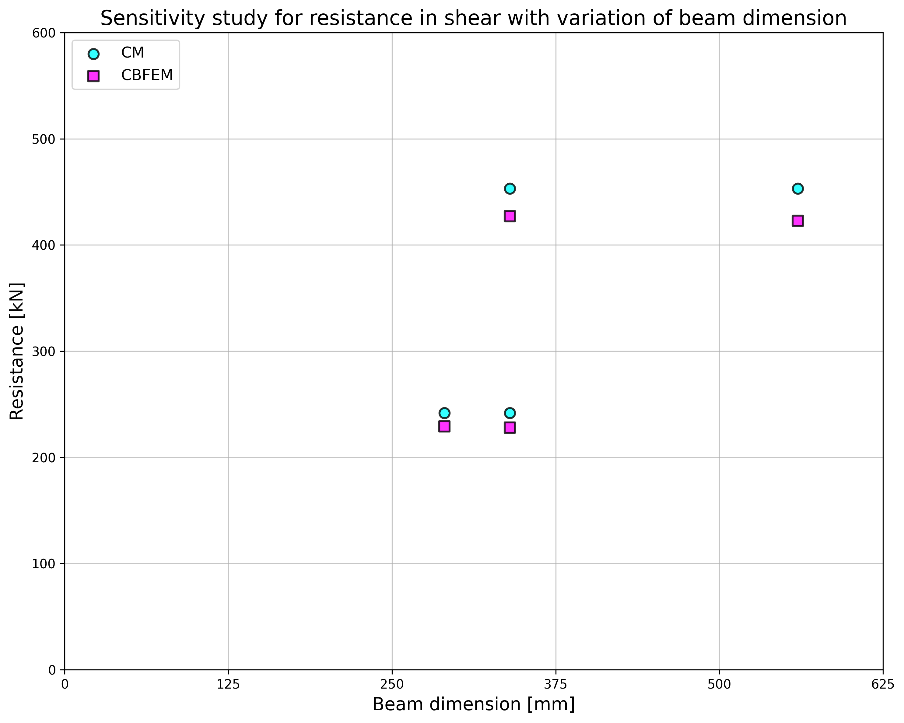
\[ \textsf{\textit{\footnotesize{Fig. 5.5.5 Sensitivity study for resistance in shear with variation of beam dimension}}}\]
Tab. 5.5.1 Parametrická studie únosnosti s variací průměru šroubu
| Parametr | AM | CBFEM | AM/CBFEM | |||||
| Nosník; čelní deska | Průměr | Vzdálenosti | MRd [kNm] | VRd [kN] | MRd [kNm] | VRd [kN] | MRd | VRd |
| IPE270; tp = 30mm; 150×310mm | M16/8.8 | e1 = 60 mm; p1 = 190 mm; w = 90 mm | 41 | 155 | 38 | 146 | 1,06 | 1,06 |
| M20/8.8 | e1 = 70 mm; p1 = 170 mm; w = 90 mm | 61 | 242 | 50 | 200 | 1,21 | 1,21 | |
| HEA300; tp = 40mm; 300×330mm | M24/8.8 | e1 = 85 mm; p1 = 160 mm; w = 150 mm | 89 | 349 | 83 | 328 | 1,06 | 1,06 |
| M27/8.8 | e1 = 95 mm; p1 = 140 mm; w = 150 mm | 110 | 453 | 89 | 365 | 1,24 | 1,24 | |
| HEA500; tp = 40mm; 330×520mm | M30/8.8 | e1 = 160 mm; p1 = 200 mm; w = 150 mm | 216 | 554 | 198 | 509 | 1,09 | 1,09 |
Tab. 5.5.2 Parametrická studie únosnosti s variací rozměru nosníku
| Parametr | AM | AM | CBFEM | CBFEM | AM/CBFEM | AM/CBFEM | ||
| Nosník; čelní deska | Průměr | Vzdálenosti | MRd [kNm] | VRd [kN] | MRd [kNm] | VRd [kN] | MRd | VRd |
| HEA260; tp = 25mm; 260×290mm | M20/8.8 | e1 = 75 mm; p1 = 140 mm; w = 130 mm | 53 | 242 | 50 | 229 | 1,06 | 1,06 |
| IPE300; tp = 30mm; 150×340mm | M20/8.8 | e1 = 70 mm; p1 = 200 mm; w = 90 mm | 69 | 242 | 65 | 228 | 1,06 | 1,06 |
| HEB300; tp = 40mm; 300×340mm | M27/8.8 | e1 = 100 mm; p1 = 140 mm; w = 150 mm | 111 | 453 | 105 | 427 | 1,06 | 1,06 |
| IPE500; tp = 45mm; 220×560mm | M27/8.8 | e1 = 105 mm; p1 = 350 mm; w = 120 mm | 220 | 453 | 206 | 423 | 1,07 | 1,07 |

\[ \textsf{\textit{\footnotesize{Drawing 5.5.1 Joint geometry and dimensions}}}\]
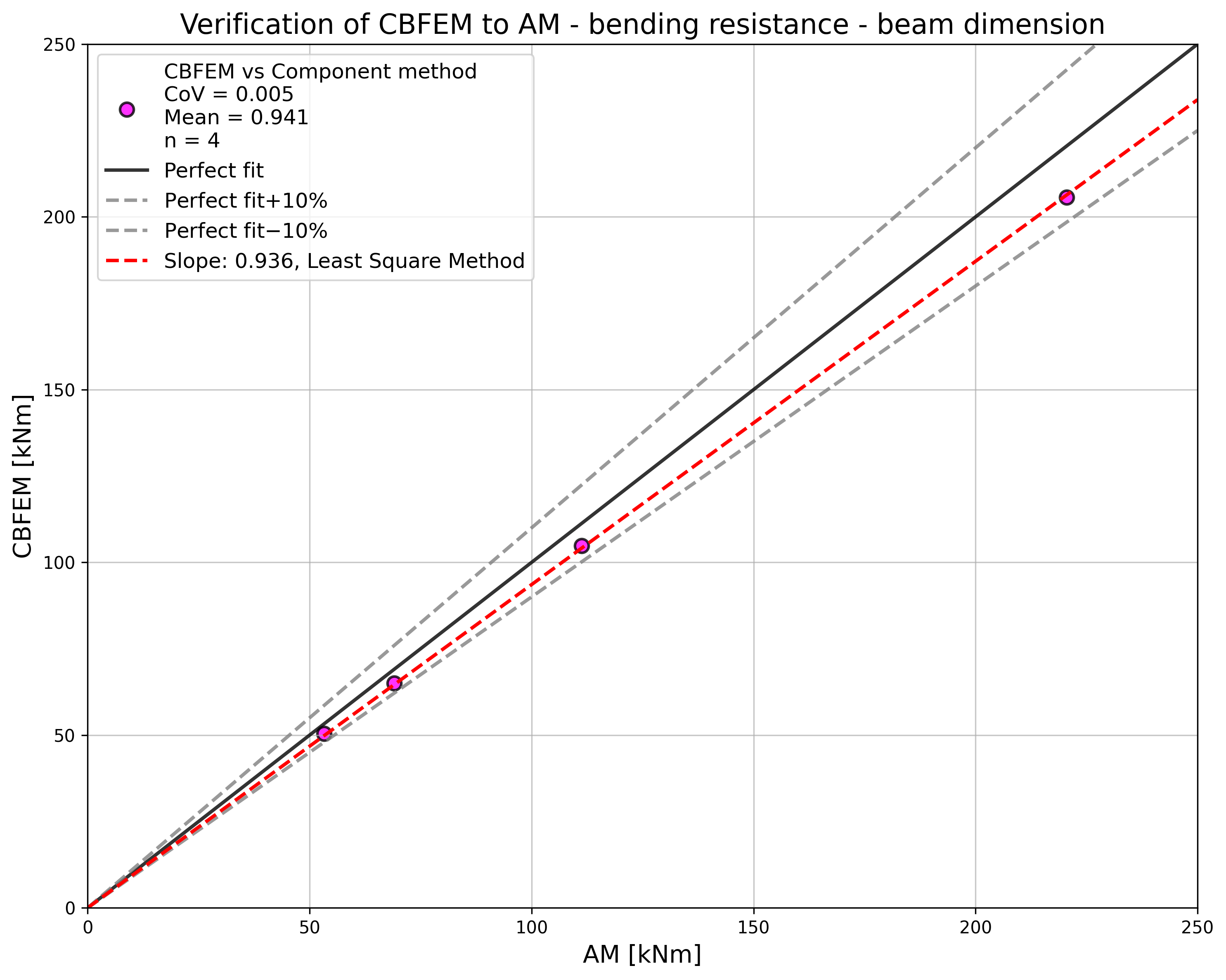
Výsledky parametrických studií jsou shrnuty v grafech na obr. 5.5.6 a 5.5.7. Výsledky ukazují, že rozdíly mezi oběma výpočetními metodami jsou pod 10 %. Analytický model obecně poskytuje vyšší únosnost.
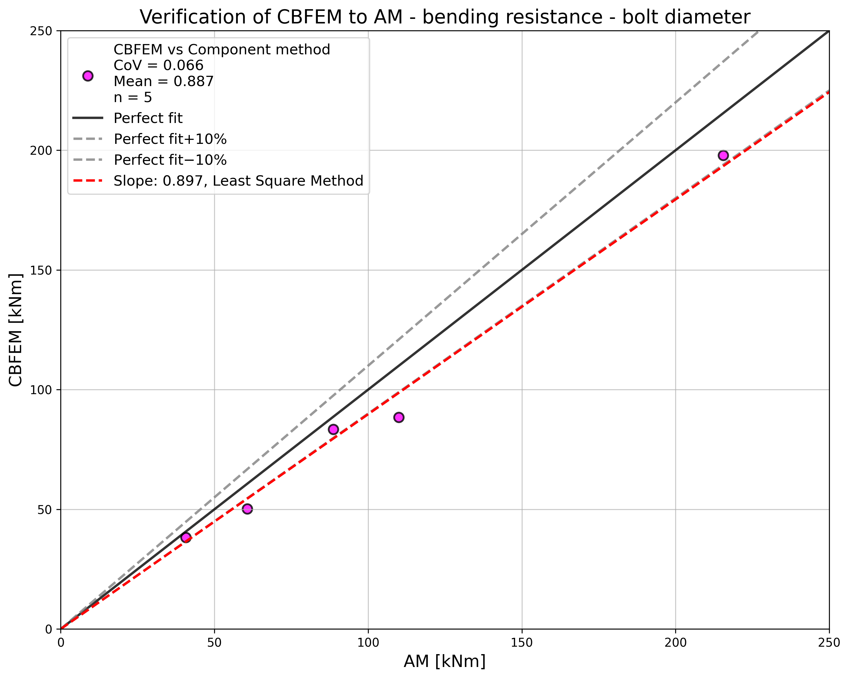
\[ \textsf{\textit{\footnotesize{Fig. 5.5.6 Verification of CBFEM to AM for the interaction of shear and tension in bolt in case of loading to bending resistance of a joint}}}\]
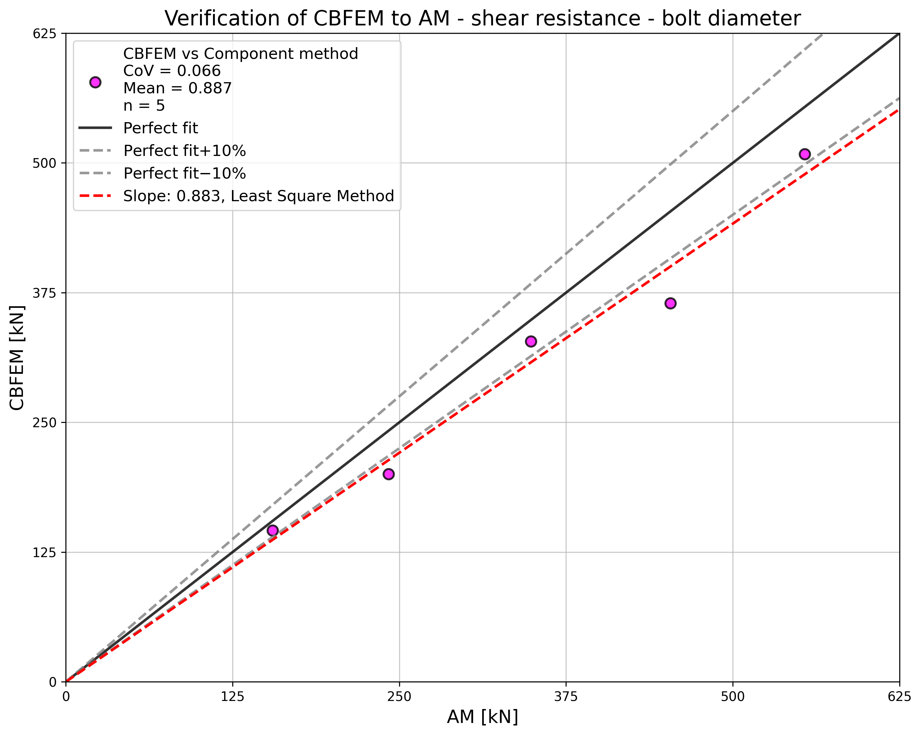
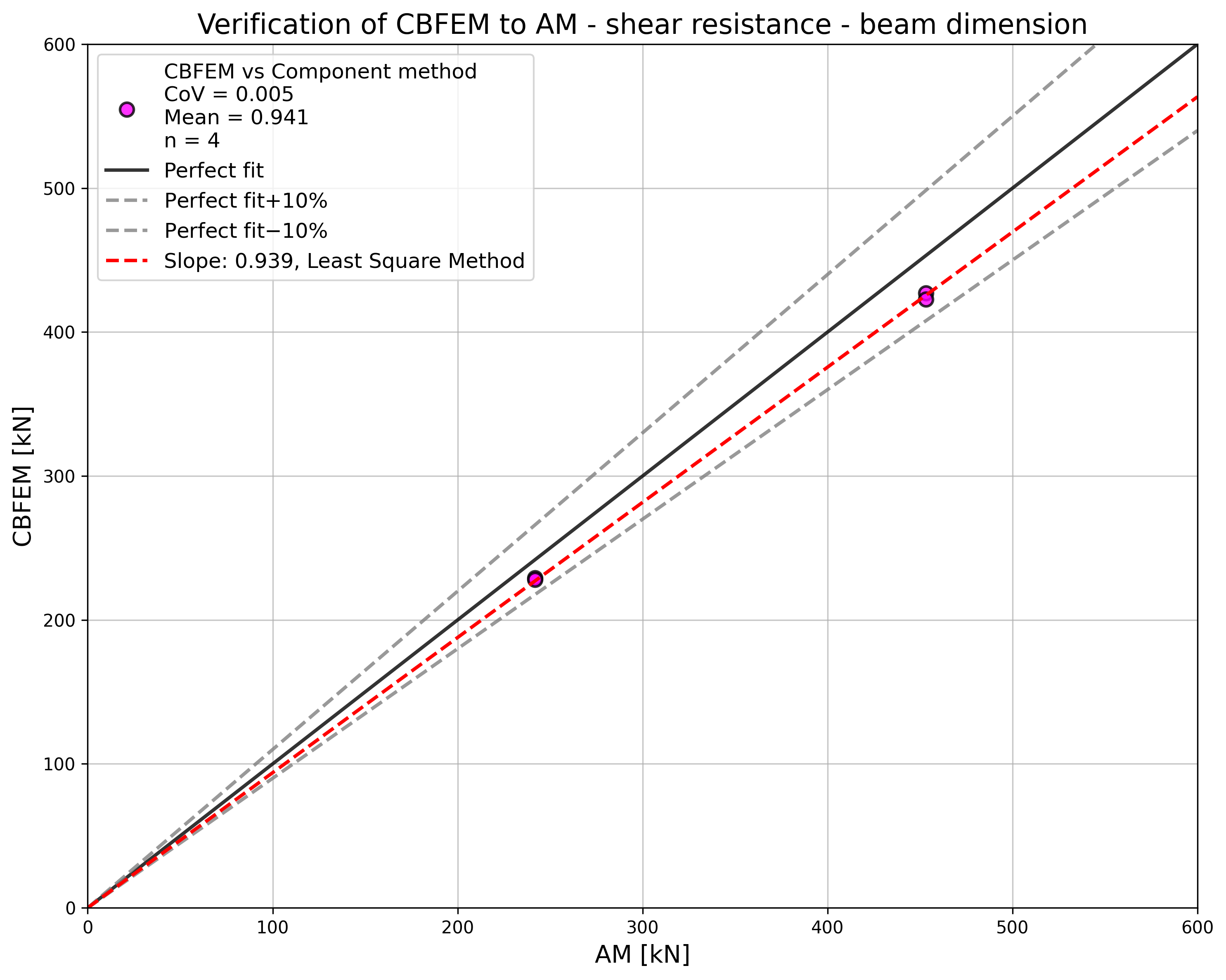
\[ \textsf{\textit{\footnotesize{Fig. 5.5.7 Verification of CBFEM to AM for the interaction of shear and tension in bolt in case of loading to shear resistance of a joint}}}\]
Vzorový příklad
Vstupy
Připojované prvky
- Ocel S355
- Nosníky HEA300
- Tloušťka čelní desky tp = 40 mm
- Rozměry čelní desky 300 × 330 mm
Šrouby
- 4 × M24 8.8
- Vzdálenosti e1 = 85 mm; p1 = 160 mm; w1 = 75 mm; w = 150 mm
Výstupy
- Návrhová únosnost v ohybu MRd = 93 kNm
- Návrhová únosnost ve smyku VRd = 291 kN
- Způsob porušení je porušení šroubu při interakci smyku a tahu