

How to activate the link
- Download and install the latest version of IDEA StatiCa
- Make sure that you are using a supported version of your FEA solution
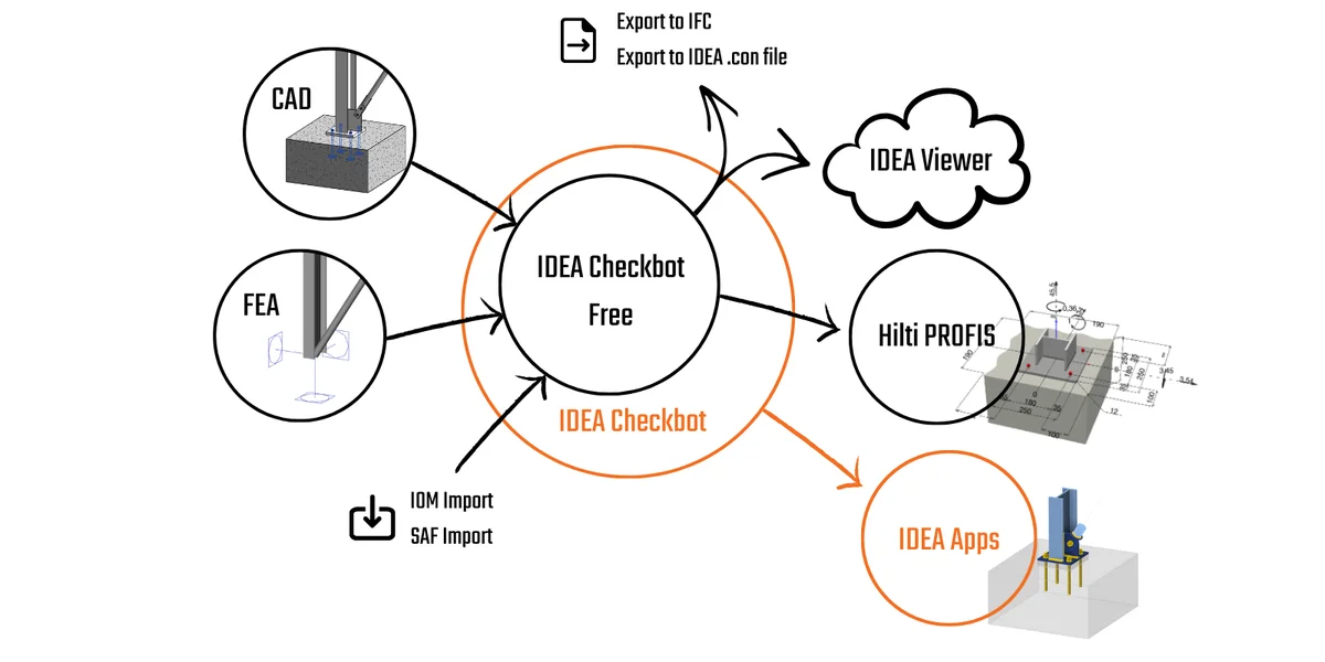
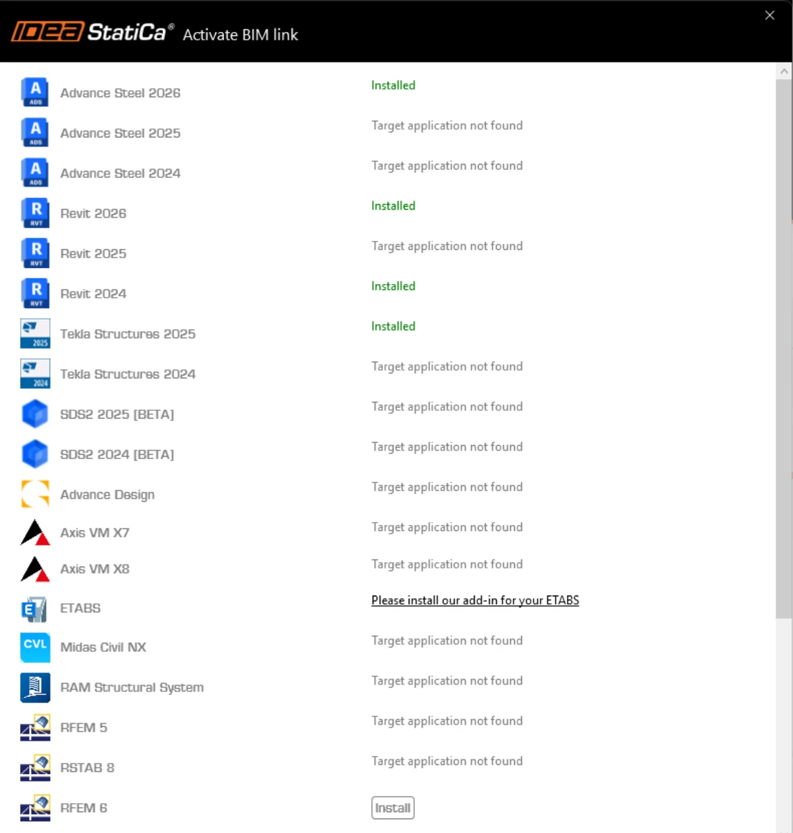
IDEA StatiCa integrates BIM links into your FEA software during its installation. You can check the status and eventually integrate more BIM links by running IDEA StatiCa and opening the BIM links. Please note that some FEA software require additional steps to fully activate their BIM link to IDEA StatiCa.
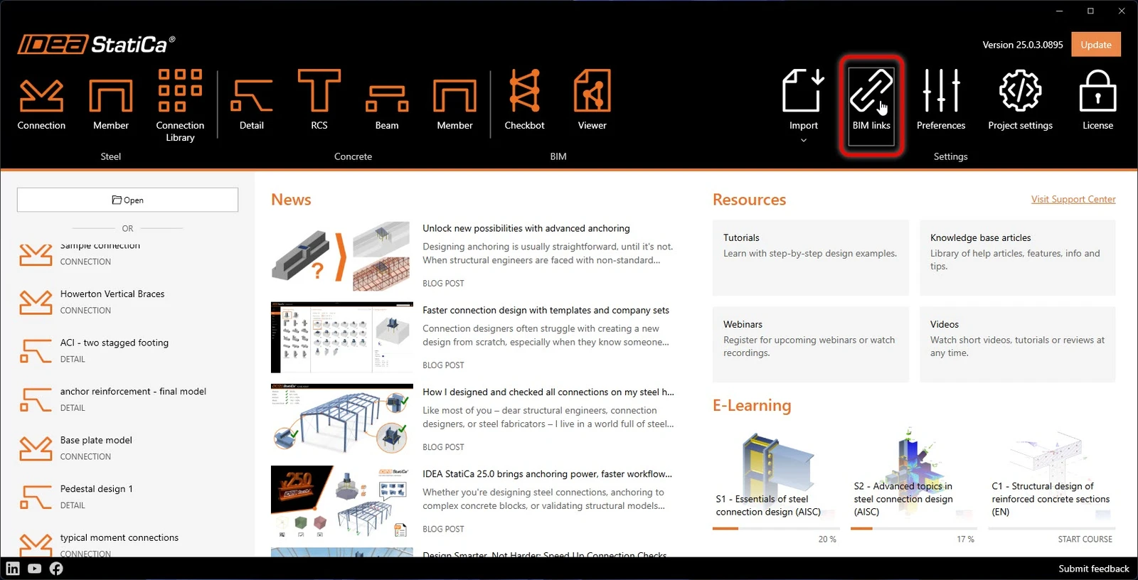
A notification "Do you want to allow this app to make changes to your device?" may appear, if so, please confirm with the Yes button.
By clicking Install, the BIM link for the selected software is integrated. The screen also tells you the status of other BIM links.
How to use the link
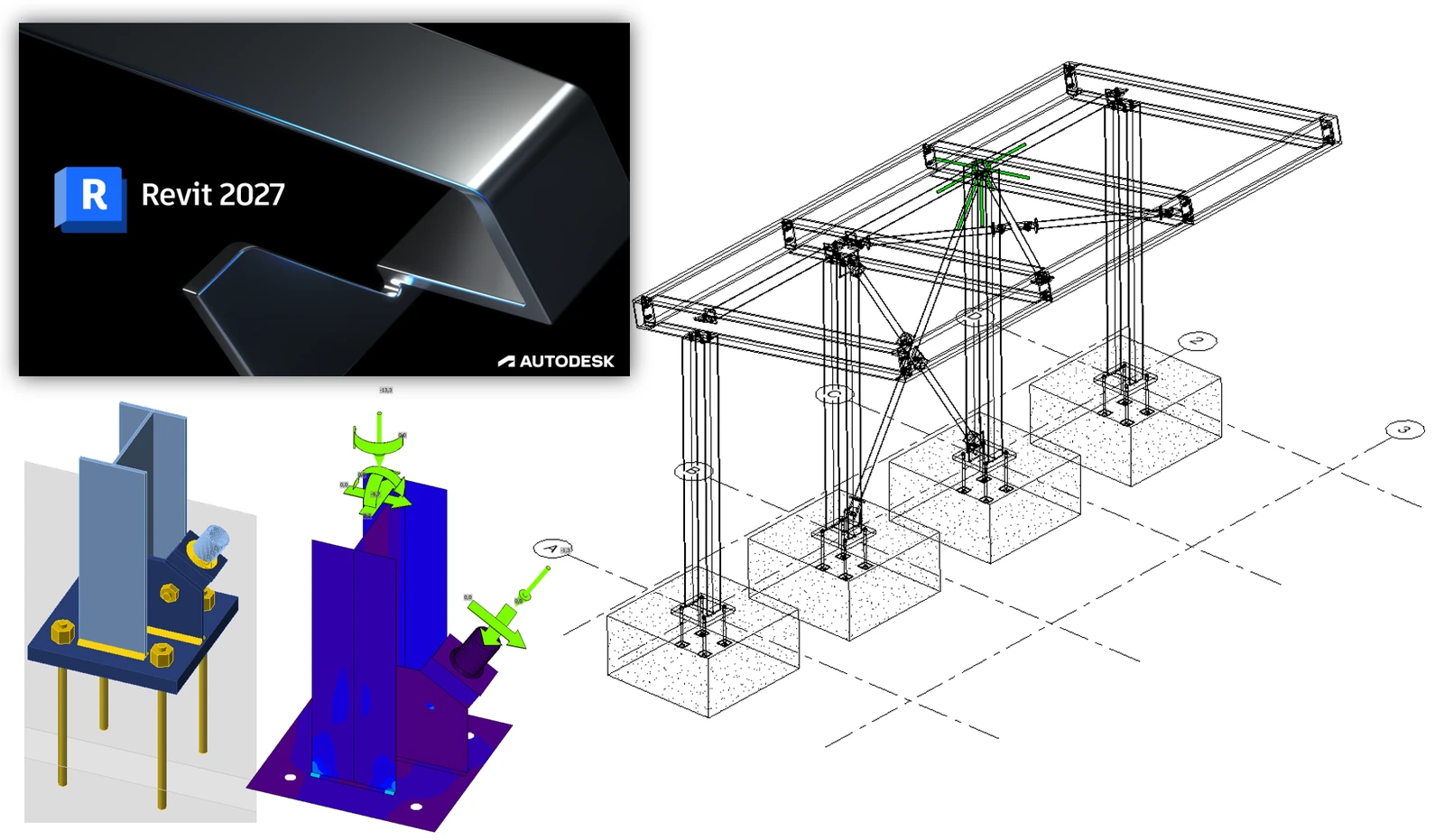
Autodesk Revit (Revit) has a feature not found in other CAD applications: it can also host results from a suitable finite element analysis solution. To that end, we have created a model for you to use in this tutorial with Revit 2025. The results have been obtained using Robot Structural Analysis 2024. Since Revit 2023, a new approach to analytical modelling has been introduced, marking a shift from automation to a more engineering-centric approach.
Open the model in Revit (note: this tutorial requires version 2025 or higher).
Two Analytical 3D views have been created to verify the loads and results.
Here are the loads that have been defined (partly in Revit and more in Robot):
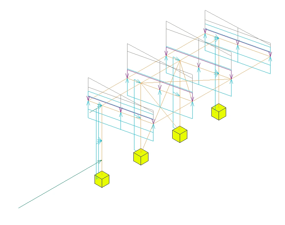
The code combinations were defined in Robot because it was much easier, and you could argue that this is the correct place to define them. Another observation here is that the model in Revit is fairly code- and country-agnostic at this stage, as the loads could be applied to any national annex to generate a 'local' solution.
Although the view is 'Locked', the results still need to be loaded. To do this, go to the Analyse tab and select Results Explorer.

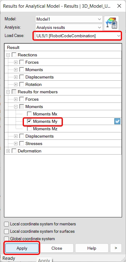
In the next window choose a suitable ULS load case combination, 'My' for example, and finally Apply.
If you expand the view (remembering to unlock it first) you will also see the legend. The text size is affected by the overall view scale so this can also be adjusted.
The results show the 'My' values for a ULS load-case combination defined in Robot.
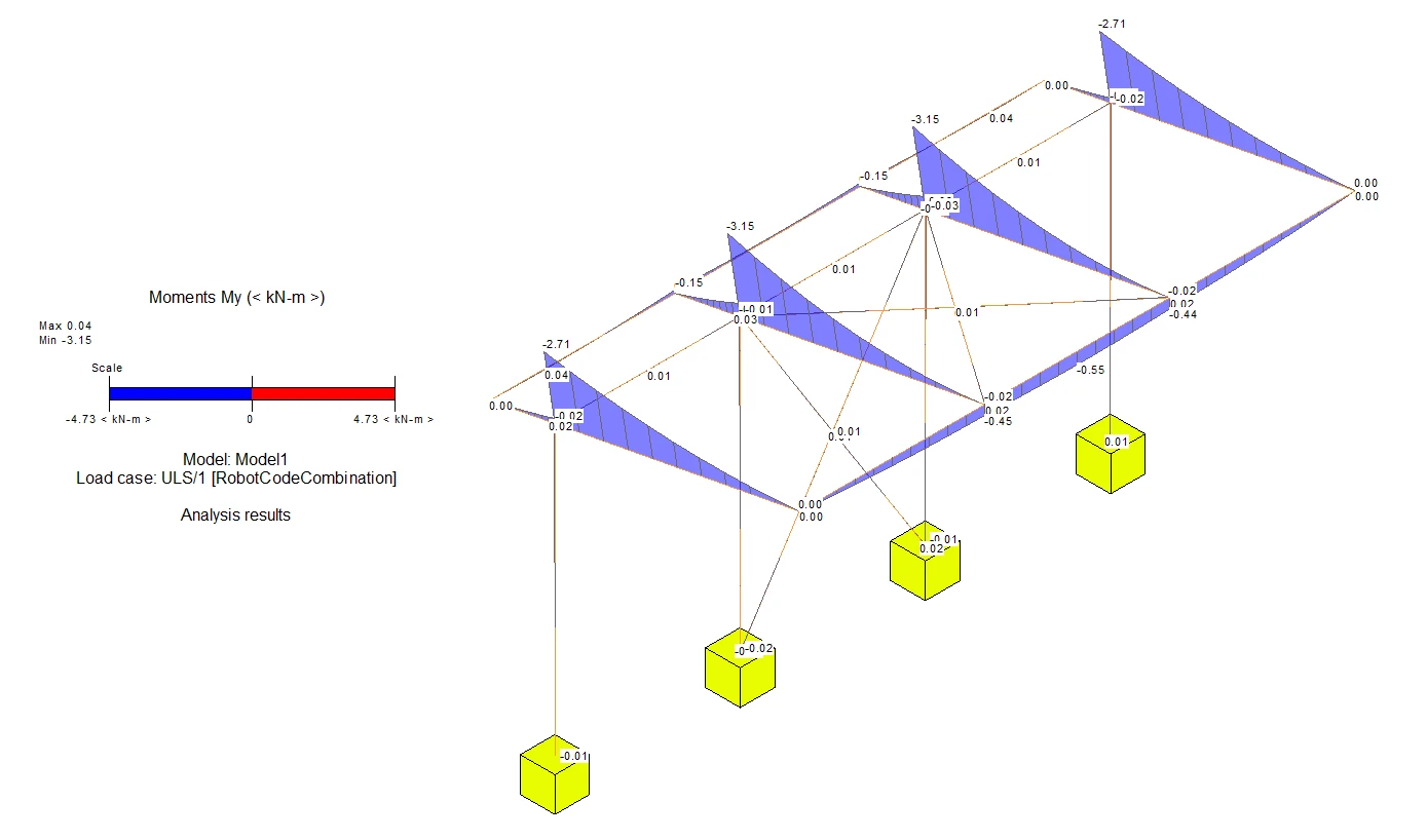
Different results can be visualised using the Results Explorer functionality from the Analyse tab.
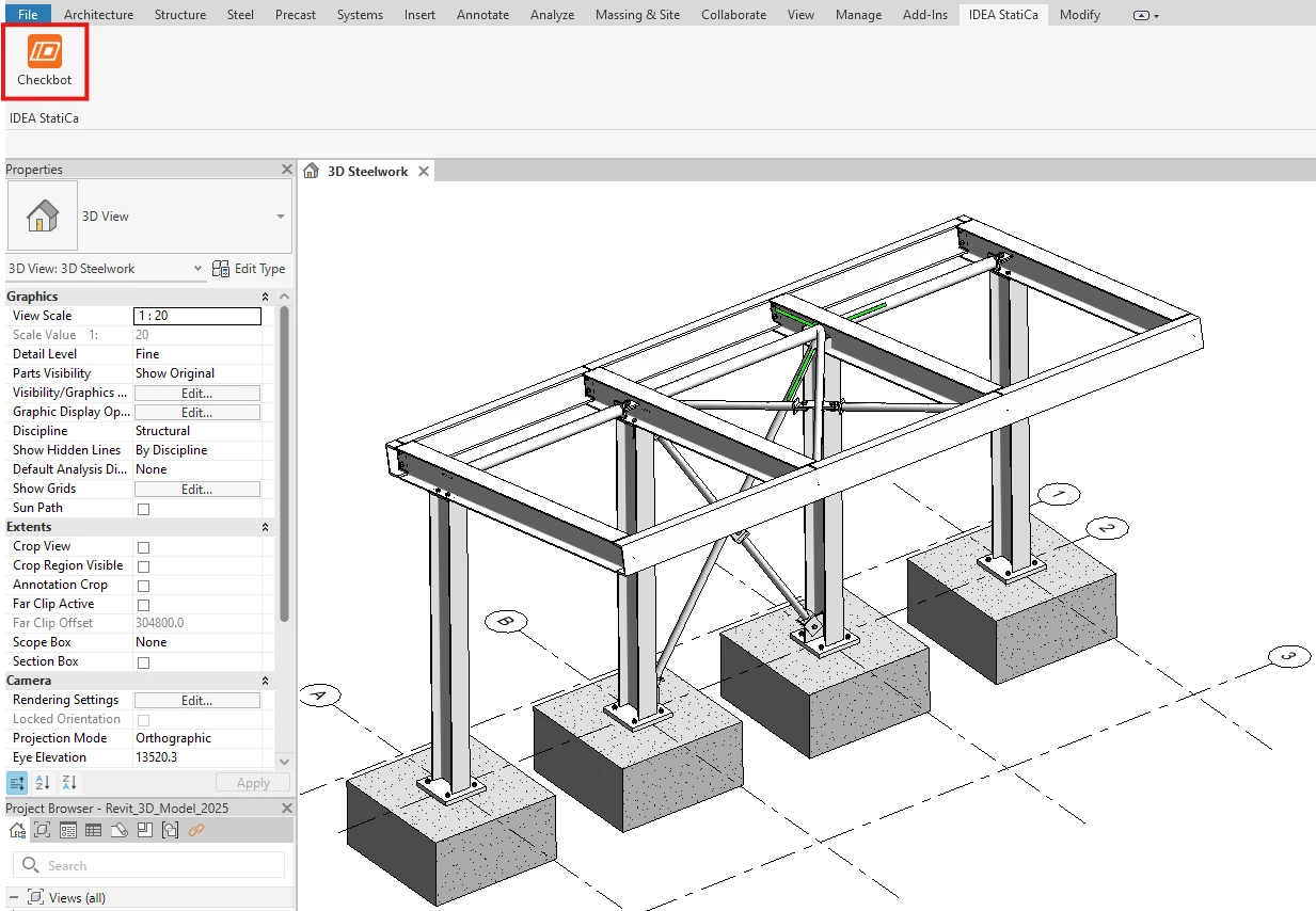
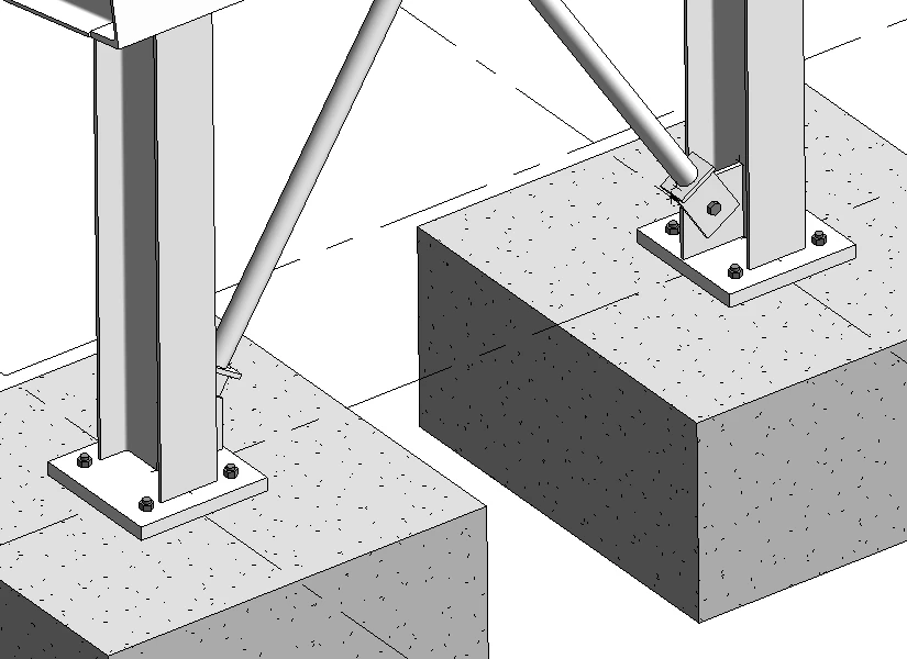
Return to the 3D Steelwork view. The steel connections shown have been modelled from within Revit. They can only be seen if the Detail Level is set to Fine.
The BIM link should be automatically integrated. You can find it in the top ribbon under IDEA StatiCa -> Checkbot. This will open the Checkbot application.
Set the following, and then select Create project.
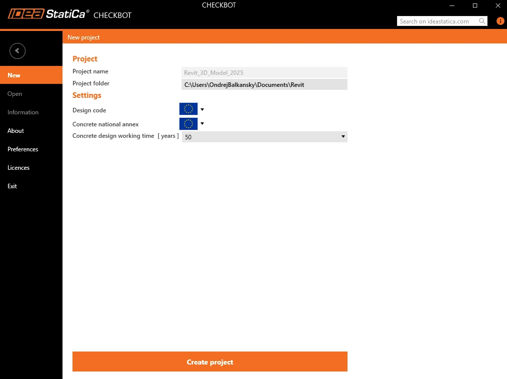
The new Checkbot project is ready to import connections from Autodesk Revit. We are going to examine the baseplate-and-brace connection at the bottom of one of the internal columns.
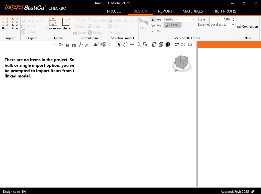
In Checkbot, select One from the Import panel mentioned above.
The focus is switched back to Revit, and you are asked to select a connection - select the brace connection.
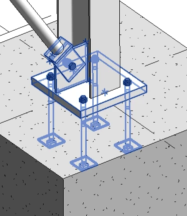
You are asked to select connection objects (these are the members and other items that make up the whole connection) - use a crossing window select.
Finally, select Finish in the top-right corner of the ribbon in Revit.
The members and connection placeholder are then imported into Checkbot.
Please see our tutorials about Checkbot and other BIM Links for more information about the Checkbot interface.
Geometry
In Checkbot, either select Open from the right-hand panel, or right-click the connection box or connection item and select Open.
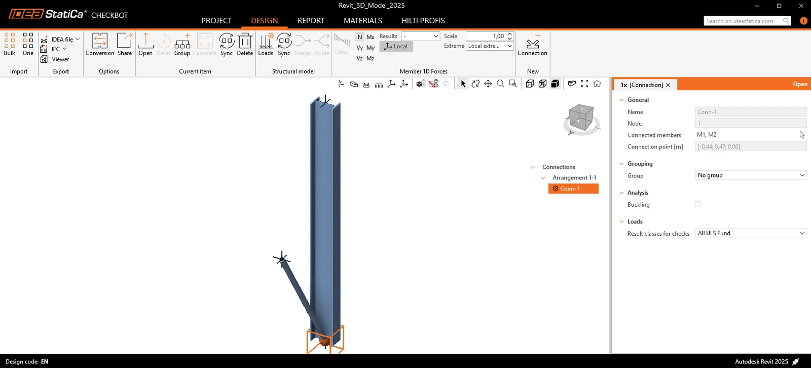
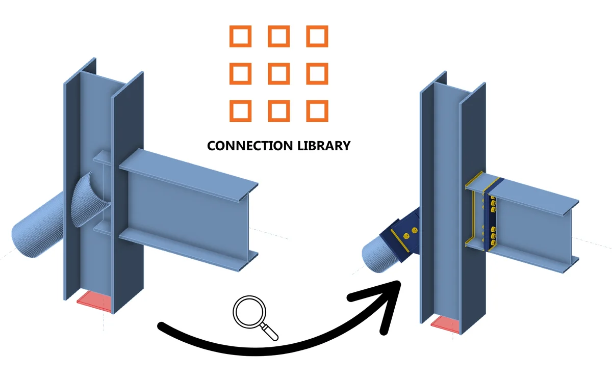
If everything has been selected as shown, you should see a view like the one in the picture below. This is where the combined geometrical and analytical approach is ideal, as it creates an instantly usable connection in IDEA StatiCa. In other tutorials based on either FEA or CAD solutions, one part is always missing. If there is no information about load effects in Revit, use any method to input the loads.
Even though the brace is modelled, we still need to set up a few things.
First, assign the correct Model Type - N-Vy-Vz. This is because only a single bolt is in use.

Second, edit the Anchors operation so that the Shear is carried by the anchors rather than by friction.
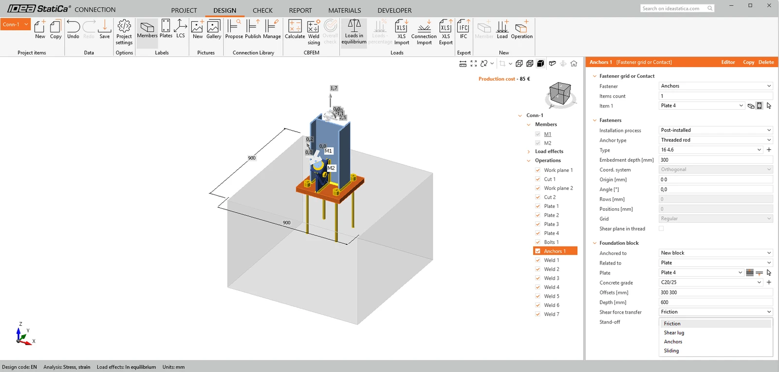
Given that the IDEA connection model originated from the Revit model, it is argued that the host information should be corrected first and then synchronised with IDEA (to keep the single source of truth just that).
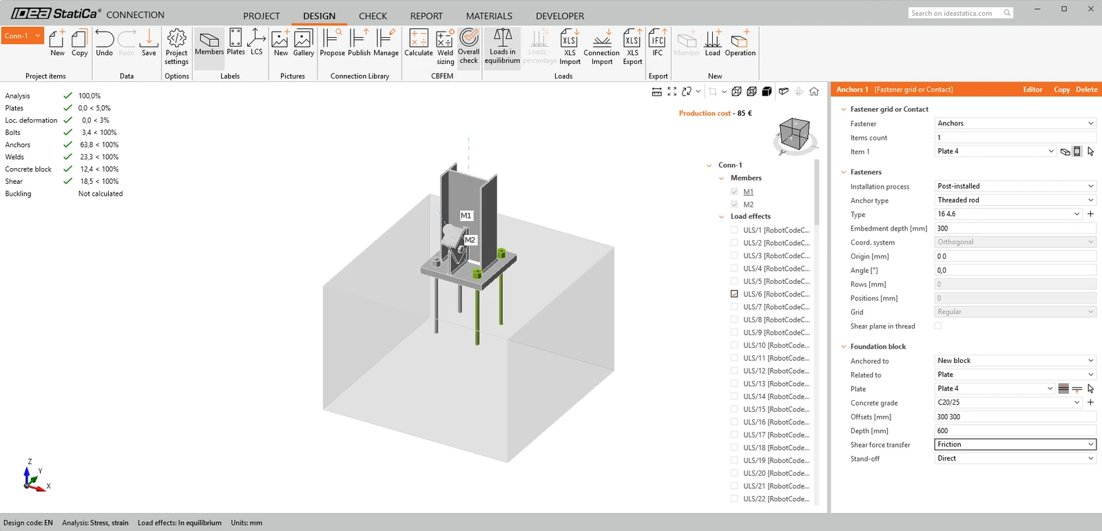
The model is now ready to be calculated. Press Calculate from the top ribbon. If there are too many combinations, unselect all load effects and select only the combination critical for this connection model; alternatively, you can use the Calculate load extremes feature. After a few moments, the initial 'traffic-light' results will appear.
Before we go, we would also like to highlight the use of a generic connection in Revit. A generic connection is used as a placeholder - a connection goes here, but I don't know what it looks like, or the actual connection is too complicated for Revit!
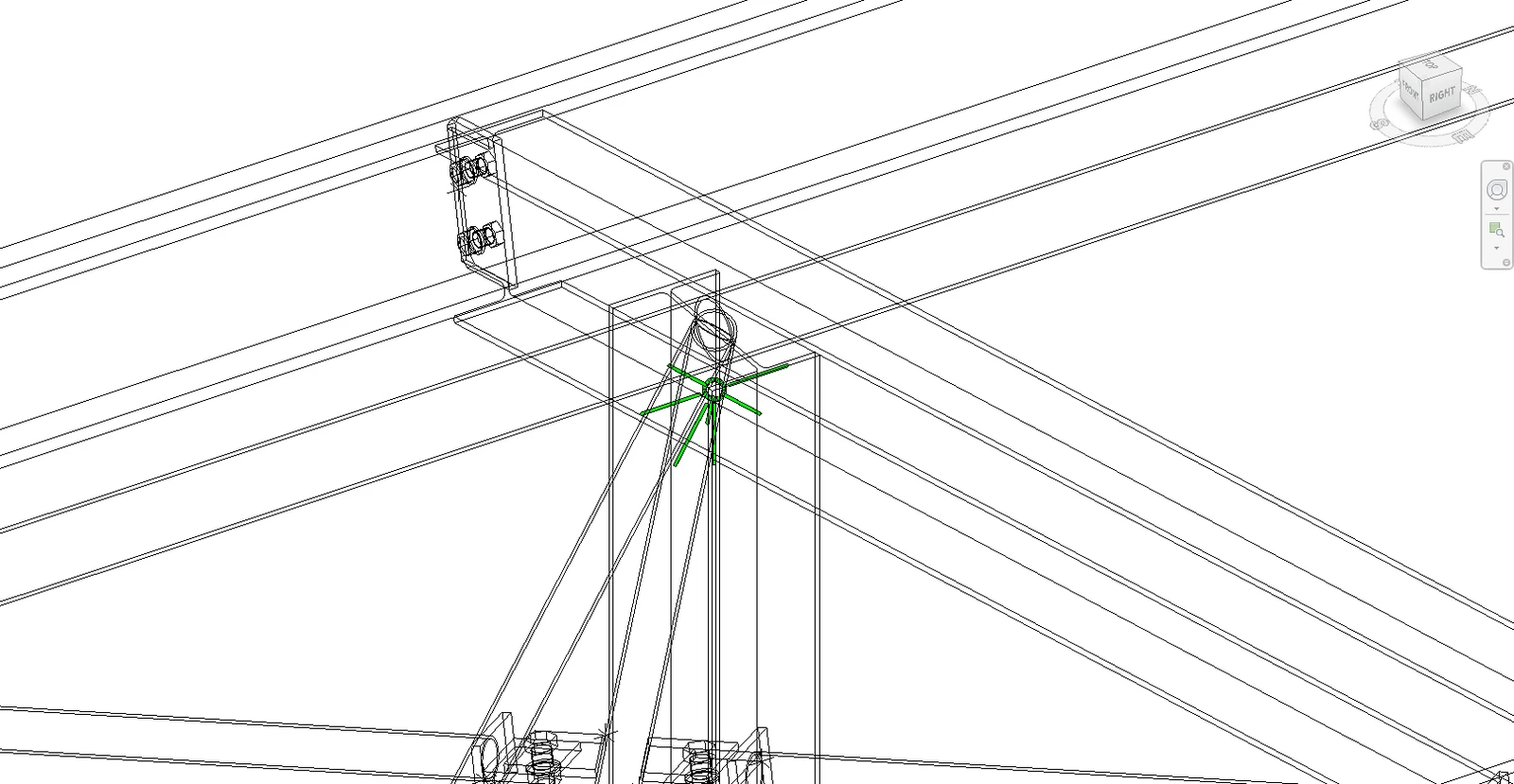
Switching to wireframe mode, you can clearly see a green connection holder on top of a column with multiple beams framing in and out. Using a workflow similar to the baseplate-and-brace example, this connection can be imported into Checkbot and edited using the Operations in IDEA StatiCa. The benefit of this workflow is not as significant as in the previous example, but it still allows you to import members and their results.
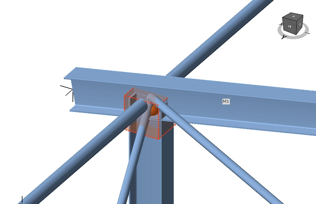
There will be times when modifications to the Revit model are required. The preferred workflow would be to make the desired geometric changes in Revit, send the model for analysis, analyse and design for those changes, and then send back any differences. Checkbot can then look for those changes.
Synchronize model
Sometimes, there are changes to your FEA/BIM model such as different member section sizes or loads. These can be synchronized between Checkbot and the FEA/BIM model.
There are two possible alternatives:
- Synchronize the Current item (if one or more joints are selected)
- Synchronize the whole imported Structural model
To test this feature you can change a member section size or shape in your BIM application or amend a load case or combination etc: change the selected column to a smaller section.
In Checkbot select the designed connections (there may be more than one) and from the Current item panel select Sync.

The Checkbot project will be updated, connection design is preserved but the results will be invalidated. You can see that the column is now updated - matching the change in the BIM model.
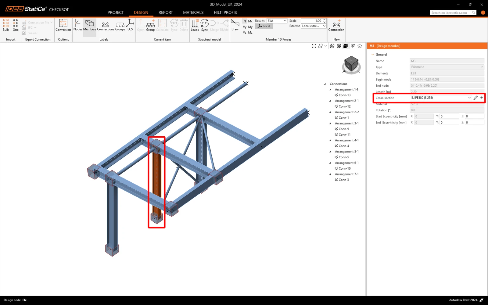
Simply code-check the highlighted connections again by selecting Calculate from the Current item panel. Please remember that bigger changes in the model might require additional validation steps with the affected connections (as above).

If the connections do not give the desired results, then you can open them again to optimize the design (i.e. strengthen if they fail the code-check or lighten if the utilization is too low).
You have successfully linked Autodesk Revit with IDEA StatiCa Connection via Checkbot. You have even explored features that allow the Revit workflow to extend beyond known, published connection types.
Want to improve your skills? Visit our Campus
Learn how to use IDEA StatiCa effectively with our self-paced e-learning courses
Start learning