Autodesk Revit BIM link for connection design (EN)
Hoe activeer je de link.
- Download en installeer de laatste versie van IDEA StatiCa
- Zorg ervoor dat u een ondersteunde versie van uw FEA/BIM-oplossing gebruikt.
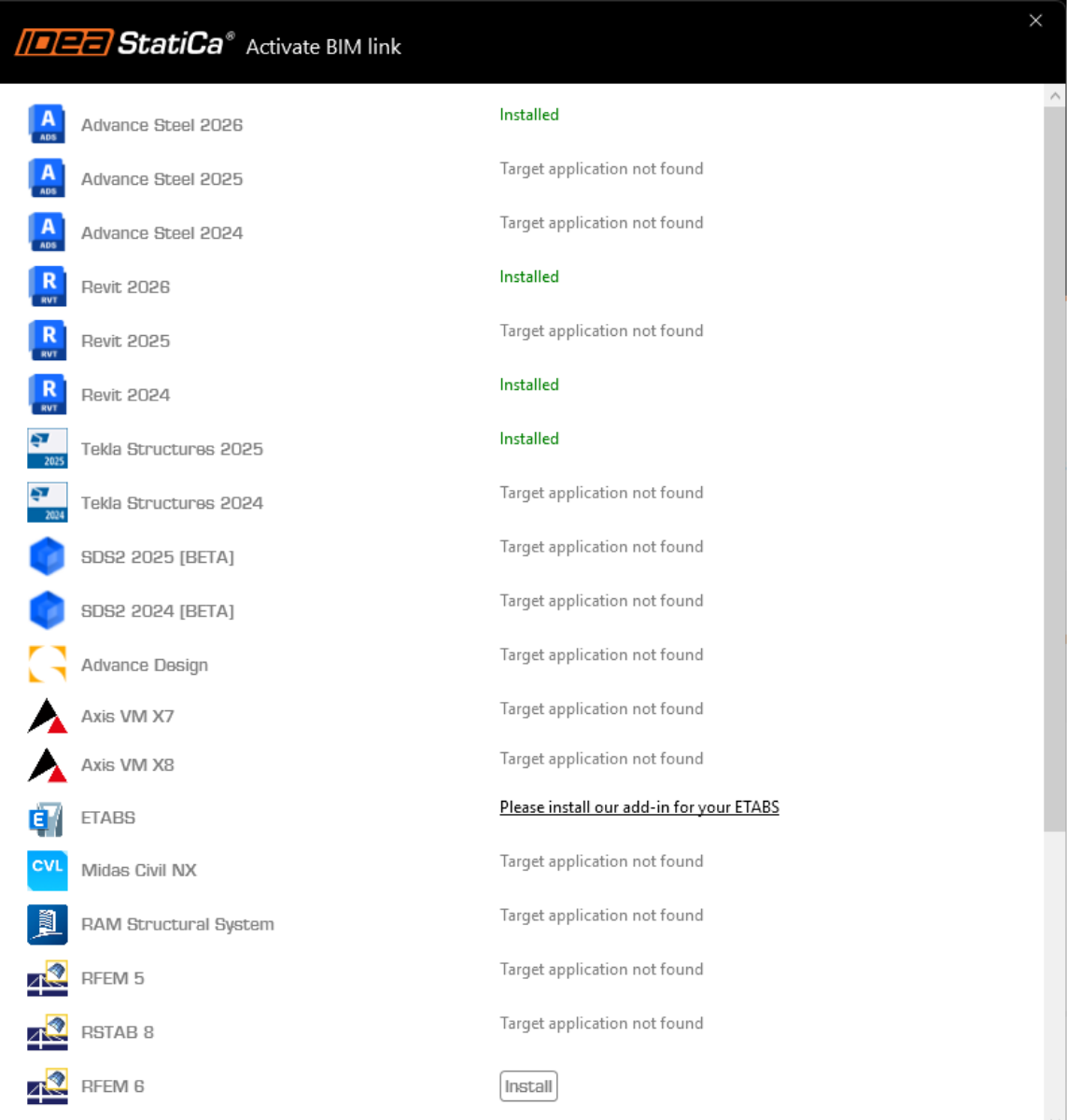
IDEA StatiCa integreert BIM-links in uw FEA/BIM-oplossingen tijdens de installatie ervan. U kunt de status controleren en meer BIM links activeren voor software die na de installering in de BIM link installer is opgenomen.
Houd er rekening mee dat sommige FEA-oplossingen extra stappen vereisen om de BIM-link met IDEA StatiCa volledig te activeren.
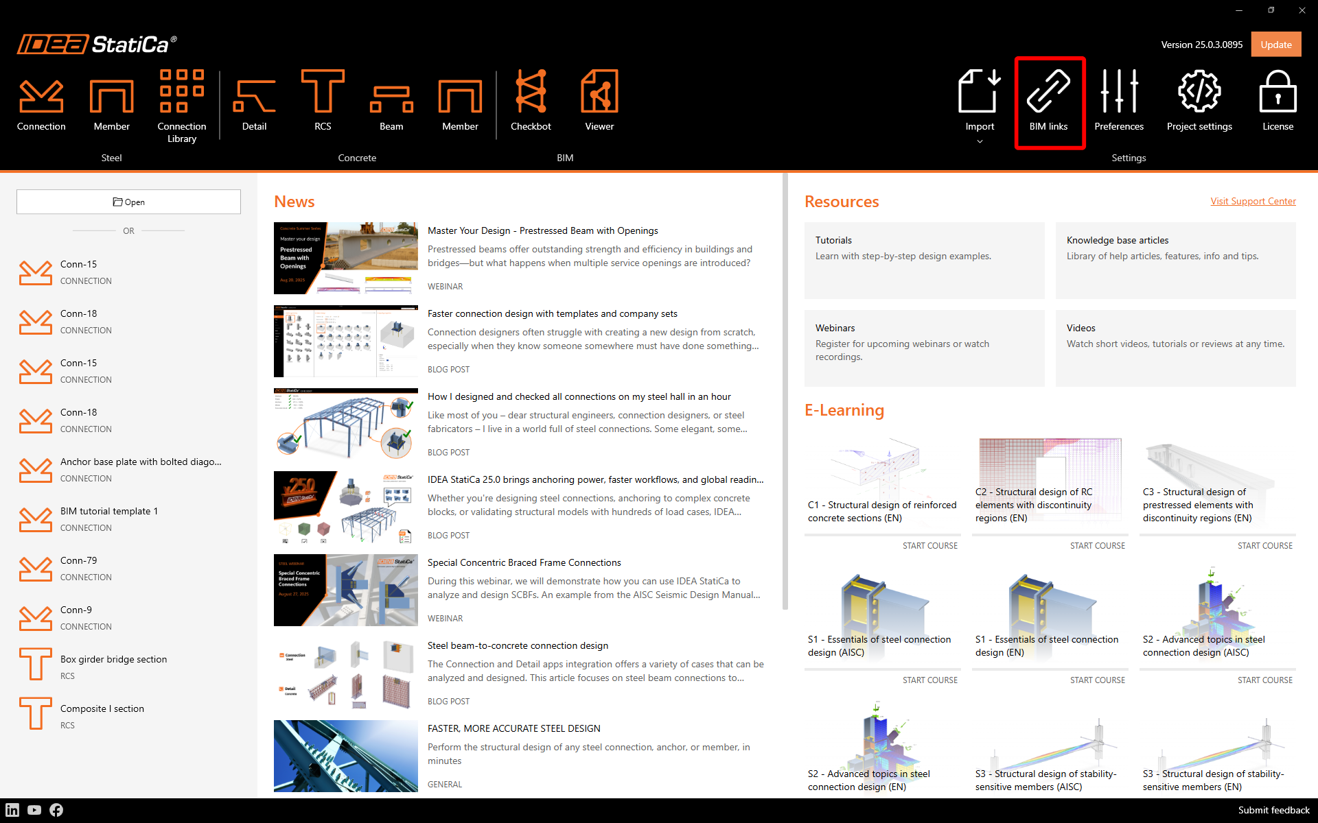
Open IDEA StatiCa en navigeer naar de BIM tab en open de BIM link installer (Activate your BIM link...).
Er kan een melding verschijnen "Wilt u toestaan dat deze app wijzigingen aanbrengt aan uw apparaat?", zo ja, bevestig dan met de Ja-knop.
De BIM-link voor de geselecteerde software (indien gevonden) wordt geïnstalleerd. Het scherm toont ook de status van andere BIM-links die mogelijk al zijn geïnstalleerd.
How to use the link
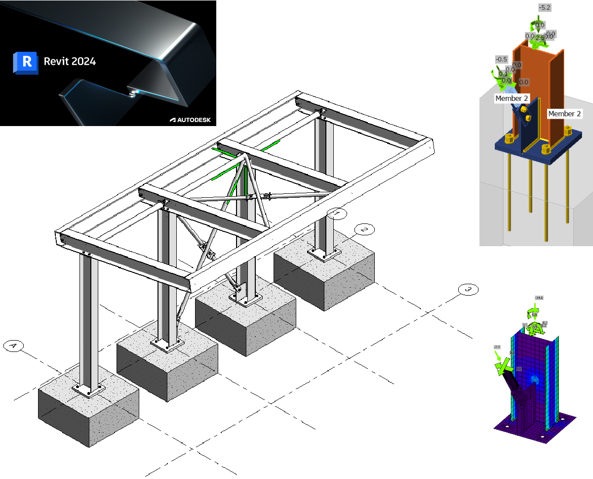
Autodesk Revit (Revit) has a feature that is not currently found in other BIM applications in that it can also host results from a suitable finite element analysis solution. To that end we have created such a model for you to use with this tutorial using Revit 2024. The results have been obtained using Robot Structural Analysis 2024. Since Revit 2023 a new approach to analytical modeling has been introduced and this has meant a move away from automation to a more engineering centric approach.
Open the model in Revit - note this tutorial requires version 2024 or higher.
There are two Analytical 3D views that have been created to verify the loads and results.
Here are the loads that have been defined (partly in Revit and more in Robot):

The code combinations were defined in Robot as this was much easier to do and you could argue that this is the correct place to define them. Another observation here is that the model in Revit is fairly code/country agnostic until this stage - as the loads could be applied to any national annex to generate a 'local' solution.
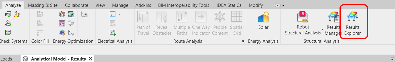
Although the view is 'Locked' the results still need to be loaded. To do this go to the Analyze tab and select Results Explorer.
In the next window choose a suitable ULS load case combination, My for example and finally Apply.

If you expand the view (remembering to unlock it first) you will also see the legend. The text size is affected by the overall view scale so this can also be adjusted.
The results show the My values for a ULS load case combination that was defined in Robot.

Different results can be visualized using the Results Explorer functionality from the Analyze tab.
Return back to the 3D Steelwork view. The steel connections shown have been modeled from within Revit. They can only be seen if the Detail Level is set to Fine.
The BIM link should be automatically integrated. You can find it in the top ribbon under IDEA StatiCa -> Checkbot. This will open the Checkbot application.

Select the New option with project type Steel and design code EN. Then select Create project.
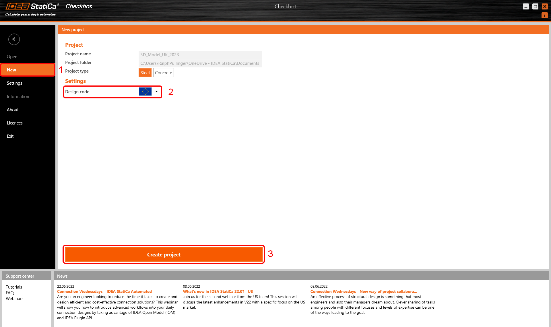
The new Checkbot project is ready to import connections from Autodesk Revit.

We are going to examine the baseplate and brace connection at the bottom of one of the internal columns.

This connection is actually two connections. One for the baseplate and one for the brace. The exception though is that the baseplate connection has been Broken (exploded) into its component parts. This is due to current limitations of the connection interaction.
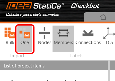
In Checkbot, select One from the Import panel.
The focus is switched back to Revit and you are asked to select a connection - select the brace connection.

You are then asked to select connection objects (these are the members and other items that make up the whole connection) - using a crossing window select the objects as shown.

Finally select Finish in the top right of the ribbon area in Revit.

The last message box that appears asks if you want to import the recommended welds - respond Yes.
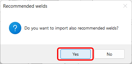
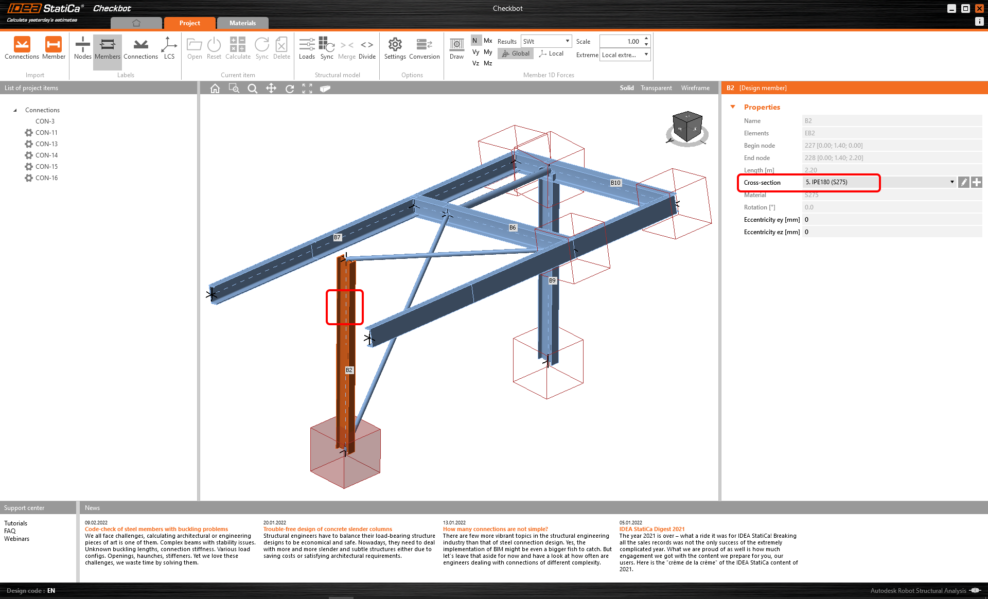
The members and connection placeholder are then imported into Checkbot.

Please see our tutorials about Checkbot and other BIM Links for more information about the Checkbot interface.
Geometry
In Checkbot either select Open from the right hand panel

or right mouse click on the connection box and select Open

or right mouse click on the connection item and select Open.

If everything has been selected as shown you should have a view that looks like this:

This is where the combined geometrical and analytical approach is ideal as it creates an instantly useable connection in IDEA StatiCa. With previous tutorials based on either FEA or BIM solutions there is always one part that is missing.

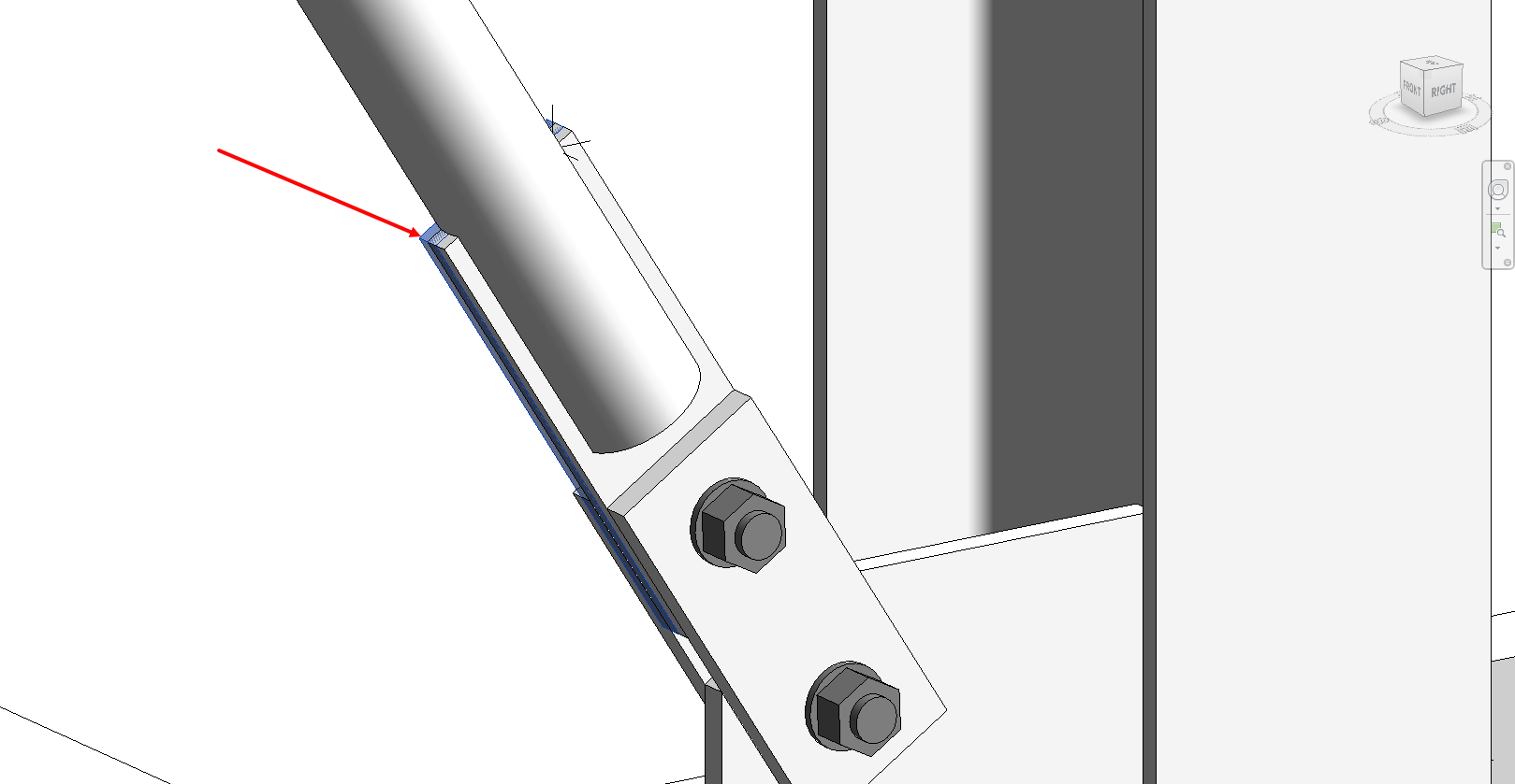
However, we do have some editing to do before we can calculate. Although the brace is modeled, we still need to assign the correct Model Type - N-Vy-Vz. This is because there is a single bolt in use. The connection, as it stands, will still produce a mechanism because there is a single bolt passing through the sandwich and fin plates. To get over this we can either introduce more bolts (which makes the connection bigger and more costly) or use a small weld on the trailing edge.
Add a weld to each sandwich plate bottom edge as it touches the fin plate:

It is also incumbent on ourselves to point out some known limitations that there is when working with Revit.
- As a result of this connection export from Revit an extra plate is generated in Revit after the connection appears in Checkbot. This should obviously be deleted. Check back here for future updates!
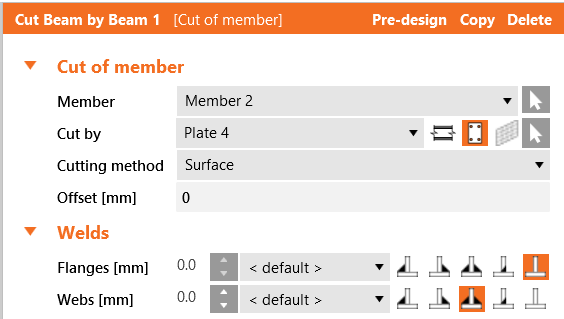
- The tubular brace is cut by a negative volume and finally welded. However, there is a better way of doing this that gives better results: cut the brace by the plate and automatically weld one to the other. Turn off NVOL 1; adjust Cut Beam by Beam 1 to the following and finally turn off Weld 6.
- If you rotate the model you will see that two welds have come over as single sided fillet when they should be double sided. For Weld 1 and Weld 5 make them double sided.
- Edit the Anchors 1 operation so that the Shear is taken by the anchors and not by friction.
Given that the IDEA connection model originated from the Revit model there is an argument that the host information should be corrected first and then synchronized with IDEA (to keep the single-source-of-truth just that).
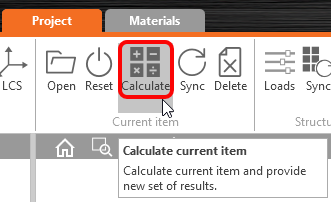
Now the model is ready to be calculated, press Calculate from the top ribbon:

After a few moments the initial 'traffic-light' results will appear.

Before we go, we would also like to highlight the use of a generic connection in Revit. A generic connection is used as a placeholder - 'a connection goes here but I don't know what it looks like' or the actual connection is too complicated for Revit!
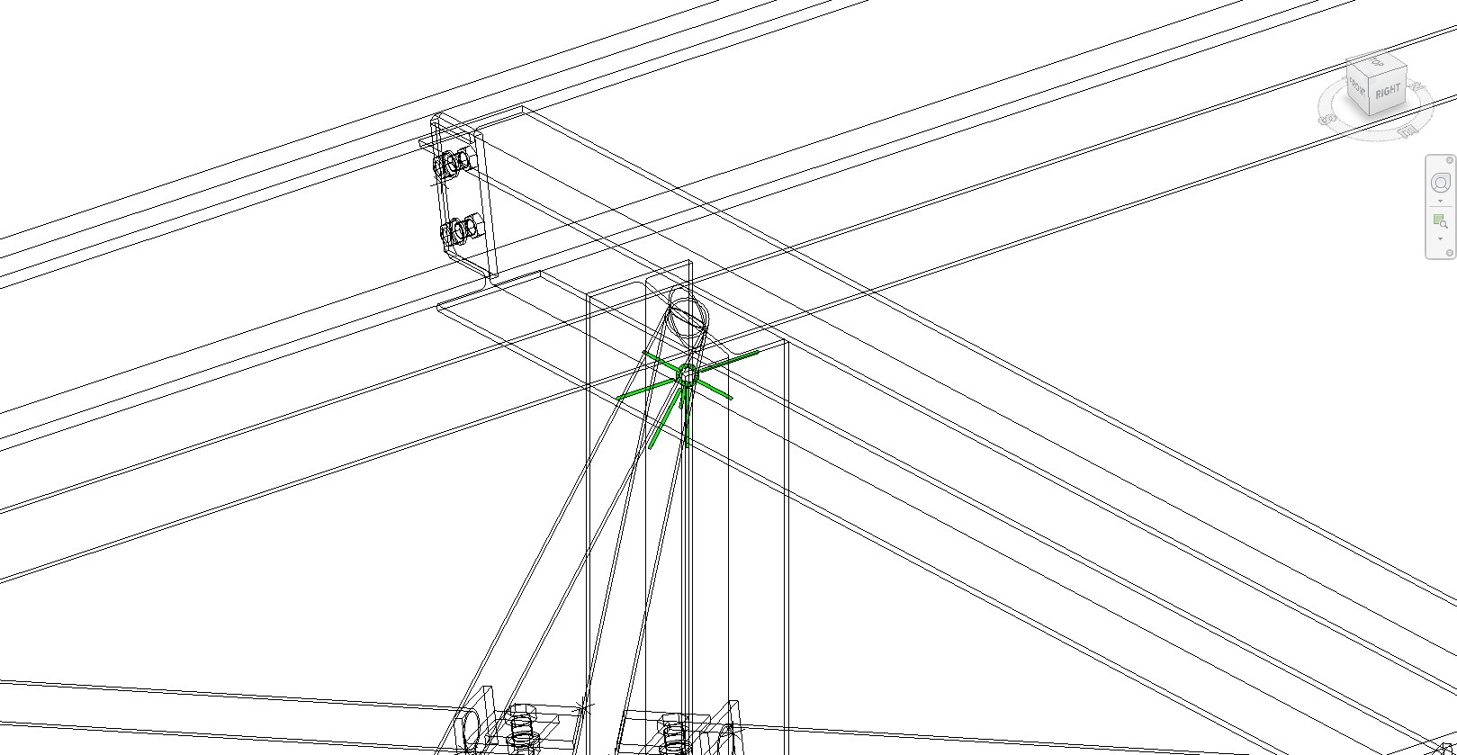
Switching to wireframe mode you can clearly see a green connection holder on top of a column with multiple beams framing in and out. Using a similar workflow to the baseplate and brace example this connection can be imported into Checkbot and edited with the Operations in IDEA StatiCa. The benefit of this workflow is not as big as with the previous example but it is a way to import the members and their results.

There will be times when modifications to the Revit model are required. The preferred workflow would be to make the desired geometrical changes in Revit, send the model for analysis, analyse and design for those changes before sending back any differences. Checkbot can then look for those changes.
Ontwerp synchroniseren
Soms verschijnen er wijzigingen in uw FEA/BIM-model, zoals andere afmetingen van de elementen of belastingen. Deze wijzigingen kunnen gesynchroniseerd worden tussen Checkbot en het FEA/BIM-model.
Er zijn twee mogelijke alternatieven:
- Het huidige item synchroniseren (als een of meer verbindingen geselecteerd worden)
- Het hele geïmporteerde structurele ontwerp synchroniseren
Om deze functie te testen kunt u in uw FEA/BIM app de grootte of vorm van een element wijzigen of een belastinggeval of combinatie wijzigen enz.: doorsnede van een geselecteerde kolom verkleinen. Vergeet niet het FEA-model opnieuw te analyseren.
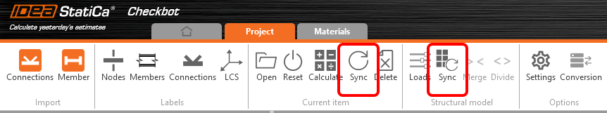
Selecteer de ontworpen verbindingen in Checkbot (er kunnen er meer dan één zijn) en selecteer Sync in het paneel Huidig item.
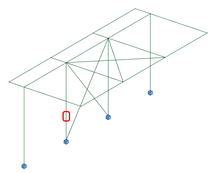
Het Checkbot-project wordt bijgewerkt, het ontwerp van de verbinding blijft behouden, maar de resultaten worden ongeldig gemaakt. U ziet dat de kolom nu is bijgewerkt - overeenkomstig de wijziging in het FEA-model.
Voer gewoon code-check van de gemarkeerde verbindingen opnieuw uit door Berekenen te selecteren in het paneel Huidig item. Vergeet niet dat grotere wijzigingen in het model aanvullende validatie met de betrokken verbindingen kunnen vereisen (zoals hierboven beschreven).
Als de verbindingen niet de gewenste resultaten opleveren, kunt u ze opnieuw openen om het ontwerp te optimaliseren (d.w.z. versterken als ze de code-check niet doorstaan of verlichten als de uitnutting te laag is).
You have successfully linked Autodesk Revit with IDEA StatiCa Connection via Checkbot. You have even explored features that allow the Revit workflow to extend beyond known, published connection types.