
Advance Design BIM link for steel connection design (EN)
How to activate the link
- Download and install the latest version of IDEA StatiCa
- Make sure that you are using a supported version of your FEA solution
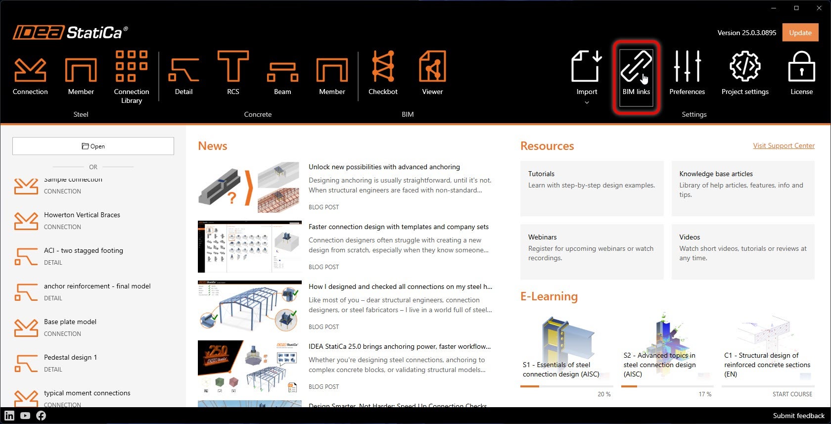
IDEA StatiCa integrates BIM links into your FEA software during its installation. You can check the status and eventually integrate more BIM links by running IDEA StatiCa and opening the BIM links. Please note that some FEA software require additional steps to fully activate their BIM link to IDEA StatiCa.
A notification "Do you want to allow this app to make changes to your device?" may appear, if so, please confirm with the Yes button.
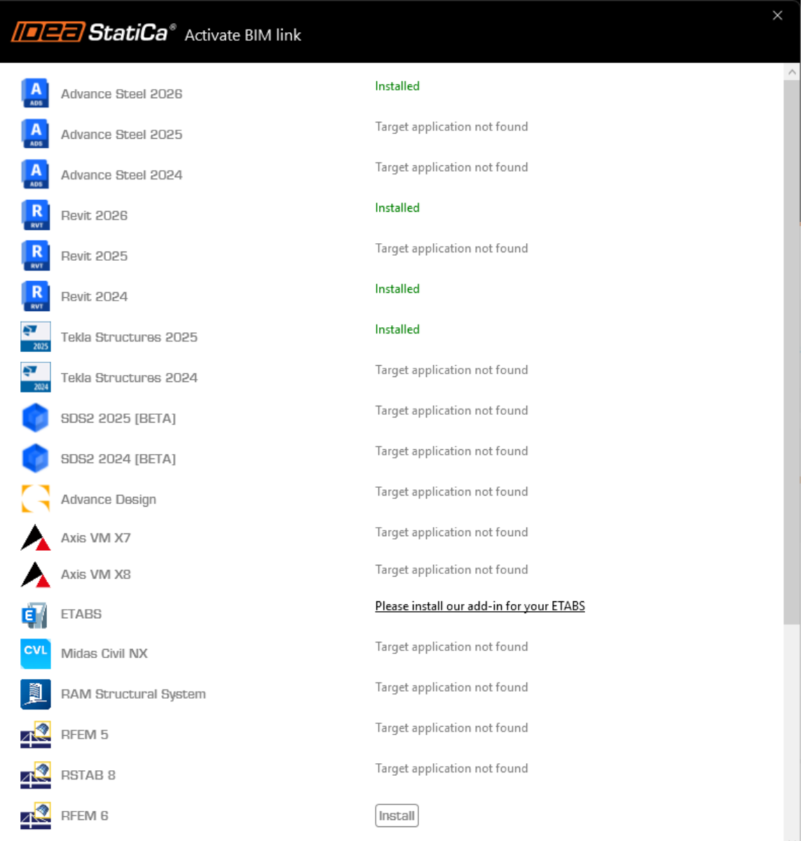
By clicking Install, the BIM link for the selected software is integrated. The screen also tells you the status of other BIM links.
How to use the link
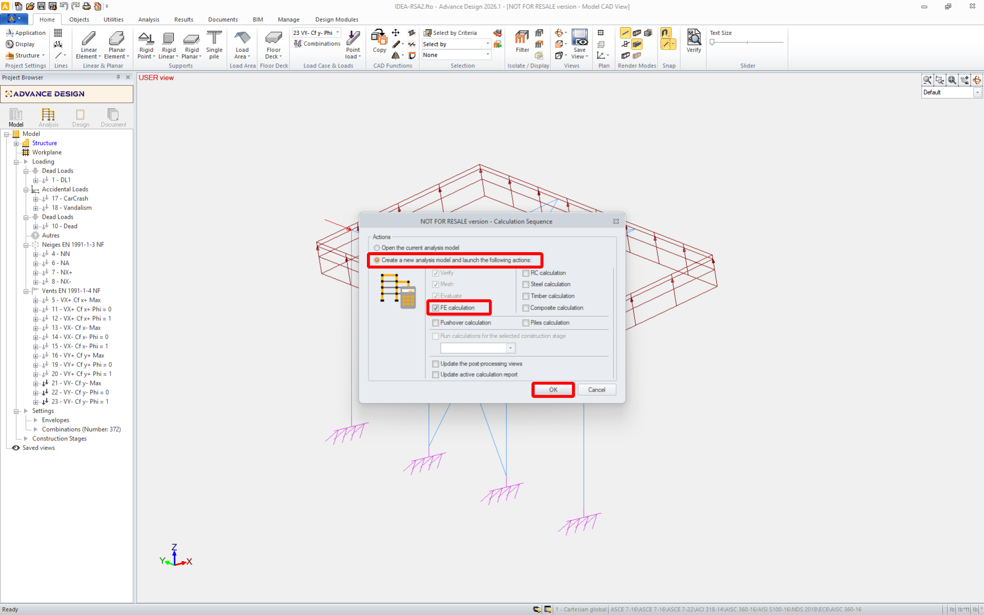
Download the attached project, open it in Advance Design, and run the linear analysis to get the internal forces over the structure.
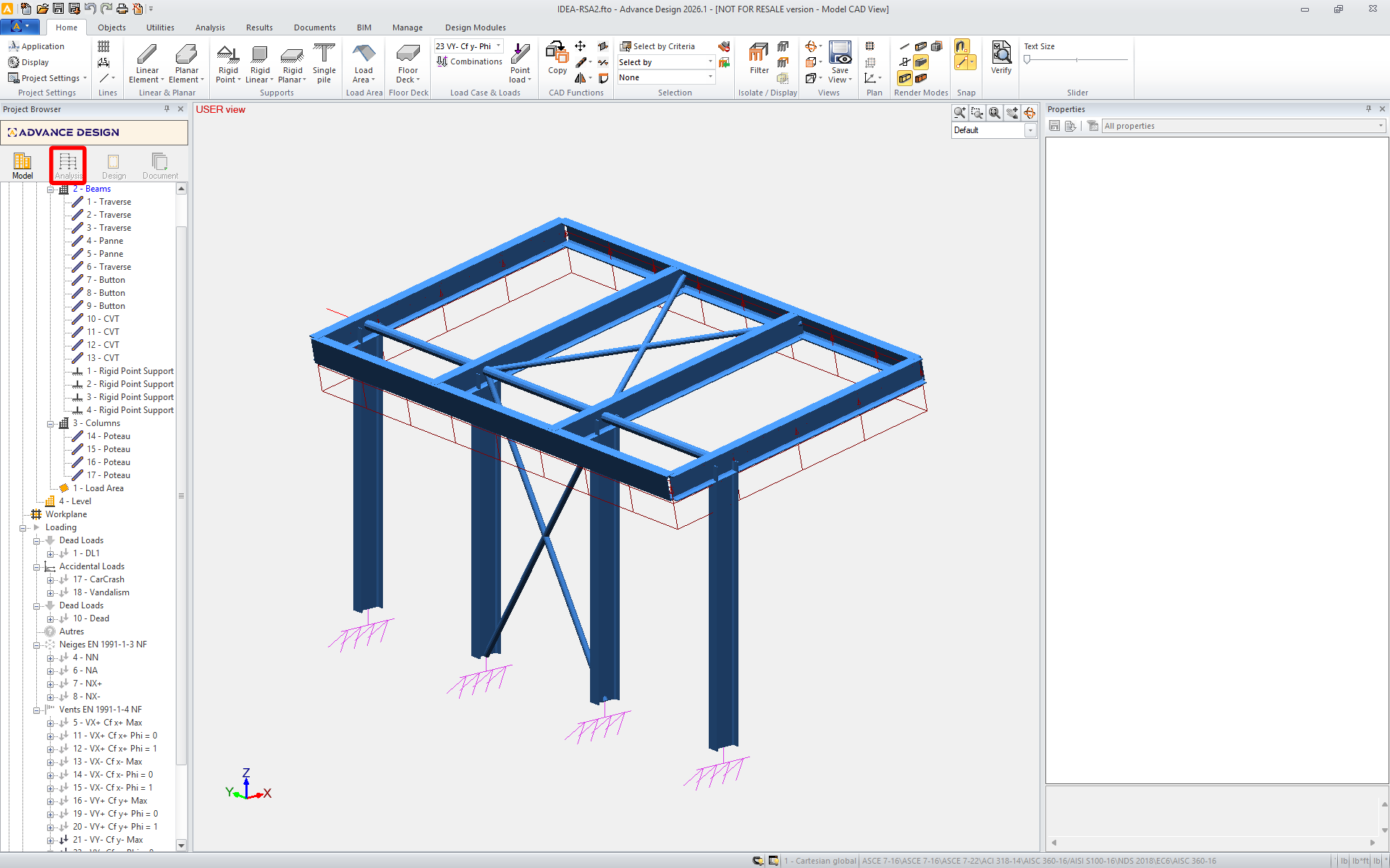
The BIM link is automatically integrated. You can find it in the top ribbon under BIM -> IDEA -> IDEA Checkbot.
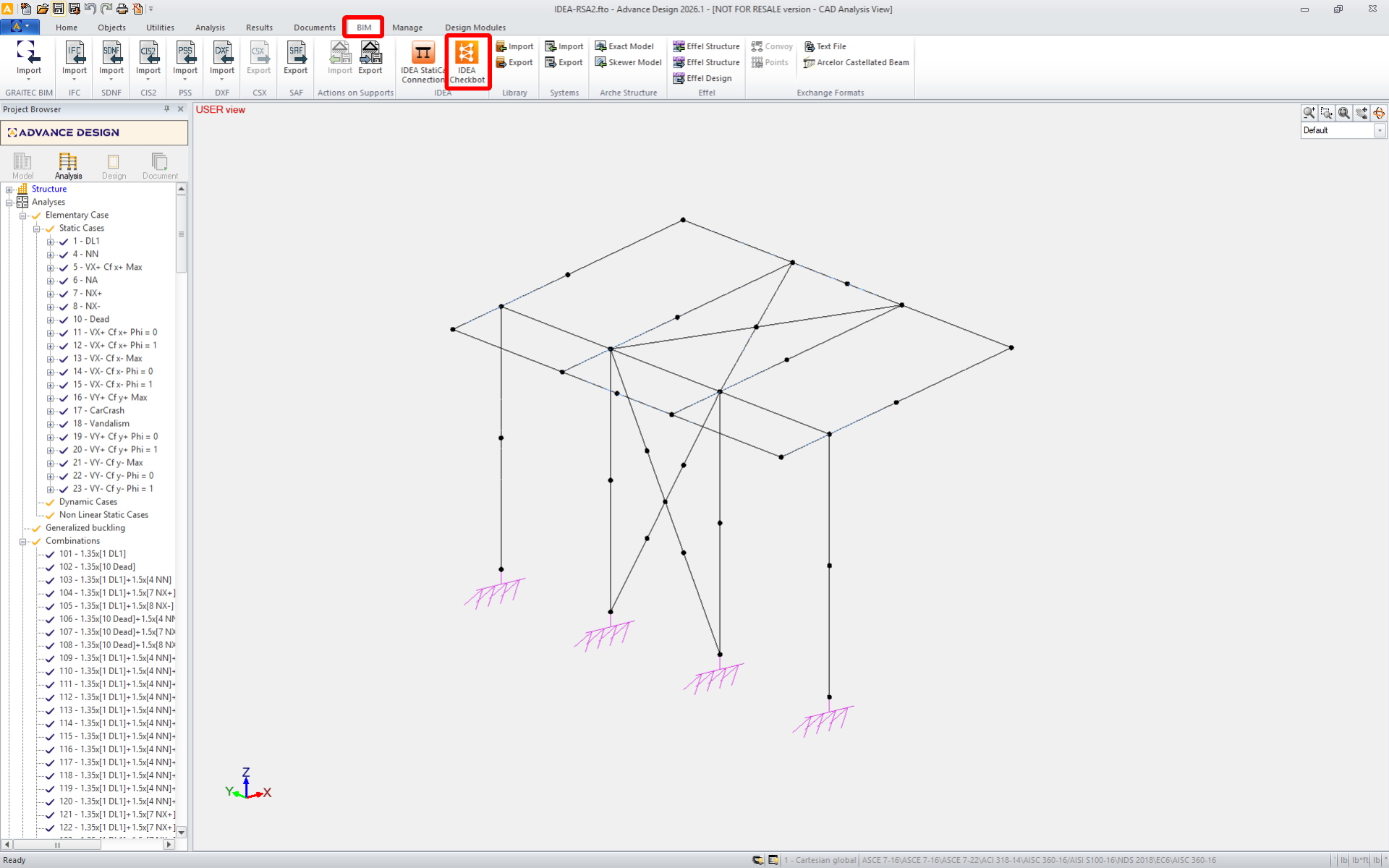
This will open the Checkbot application.
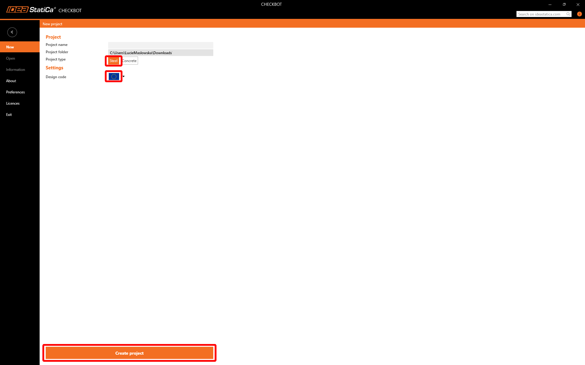
Select the New option with project type Steel and design code EN. Then select Create project.
The new Checkbot project is ready to import connections.
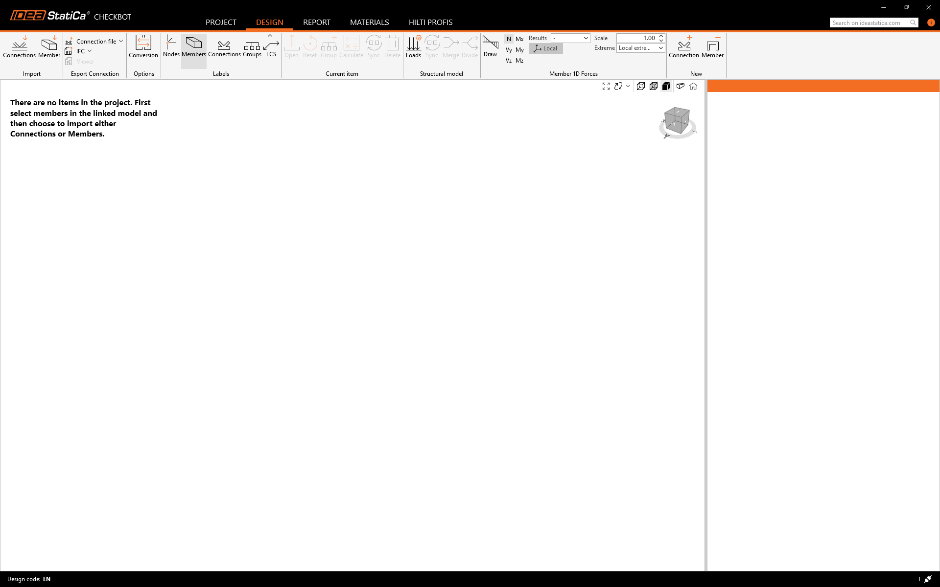
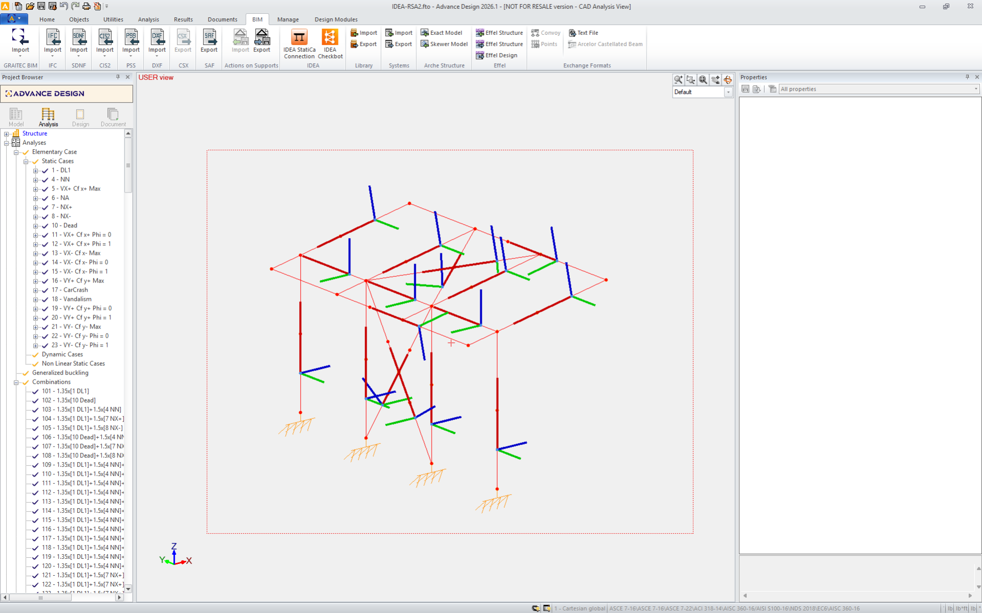
Select the structure in Advance Design and press Connections in the Checkbox.
During the import, a Conversion dialog may appear if some cross-sections are not automatically recognized. Manually assign the correct materials or profiles to proceed.
Note: Checkbot remembers your mapping. Future imports of elements with identical parameters will be recognized automatically, skipping this step.

Proceed with the import to transfer the structure and load effects into Checkbot, retaining the original coordinates, orientations, and cross-sections. Note: Node and member numbering may differ from your FEA model.
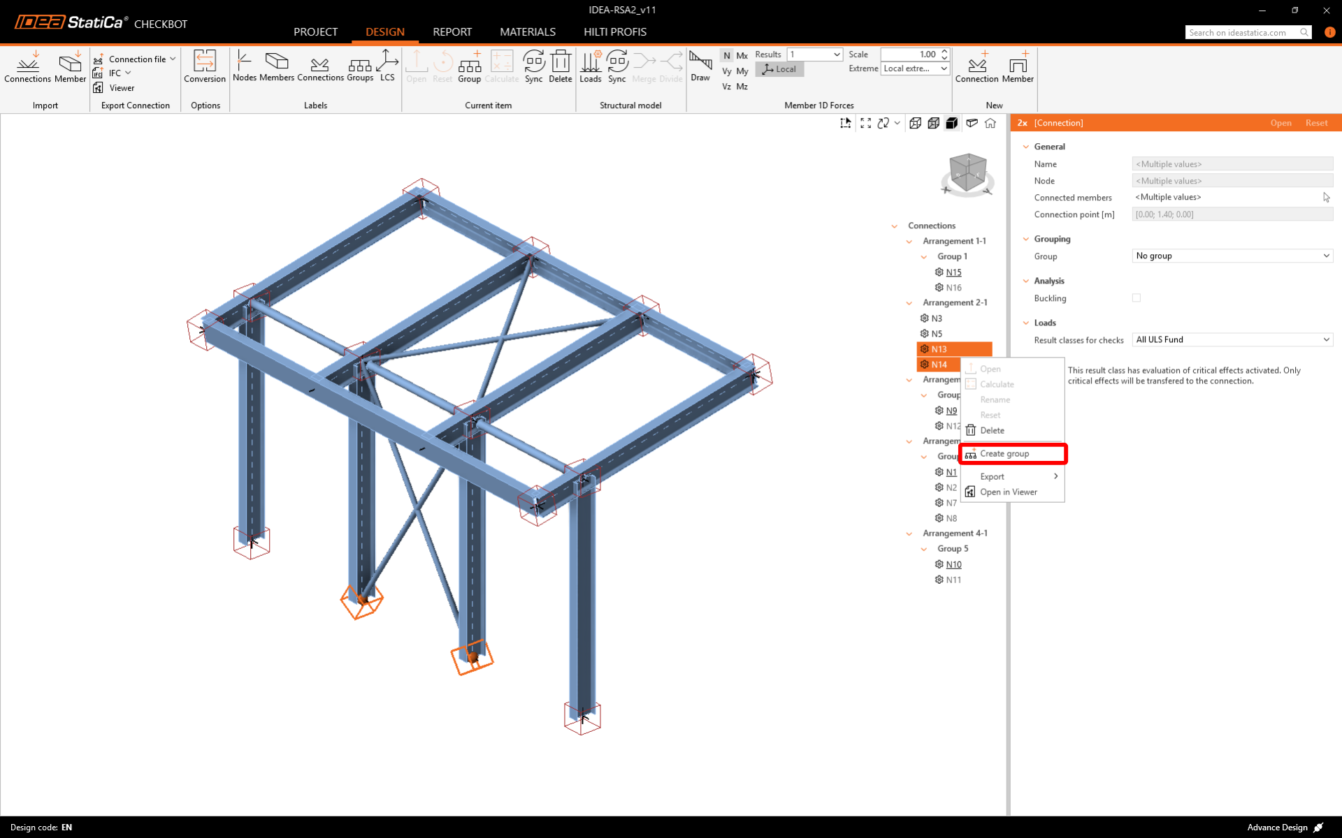
The grouping functionality automatically creates groups of connections based on typology and/or cross-sections. Every group is represented by the reference connection (underlined in the tree), which is automatically designated as the parent connection that drives the design for the whole group. All other connections are treated as child connections.
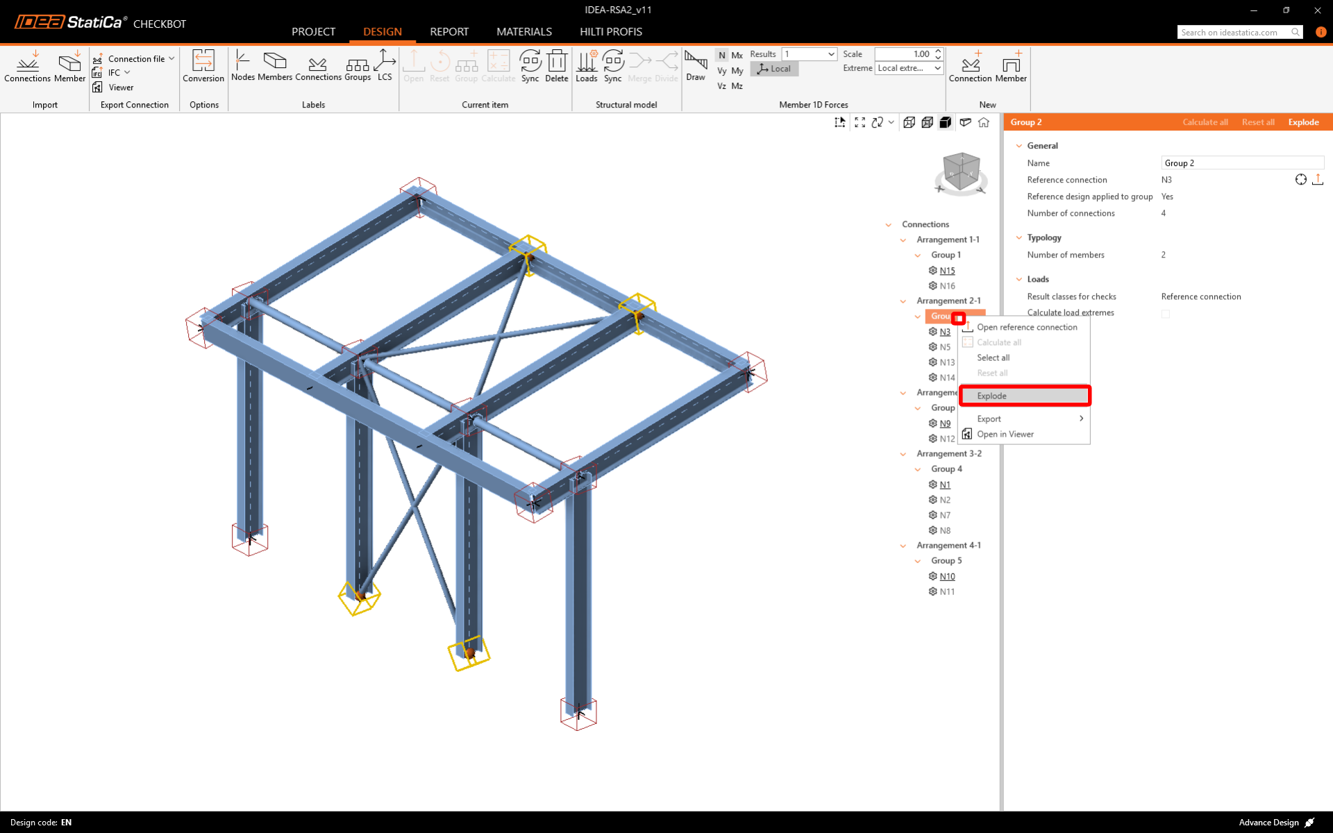
If the groups aren´t created correctly, like in this case, you can Explode them and create new ones.
You can review and adjust the imported load cases and combinations in the Loads dialog. All imported load cases and load combinations are listed on the left side, and the result classes used for checks are in the middle. If some load cases are not relevant for your design verification, exclude them by right-clicking on the selected loads and removing them from the result classes list.

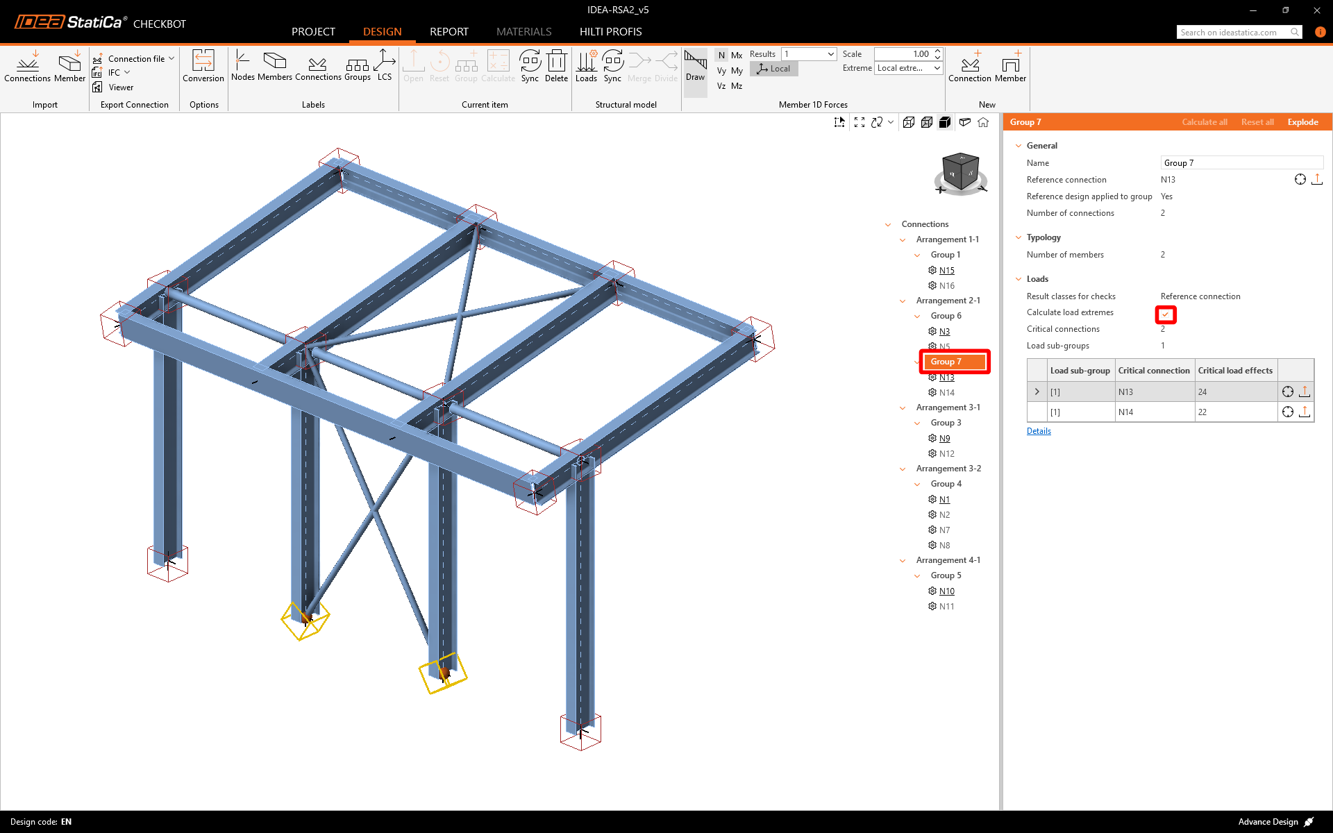
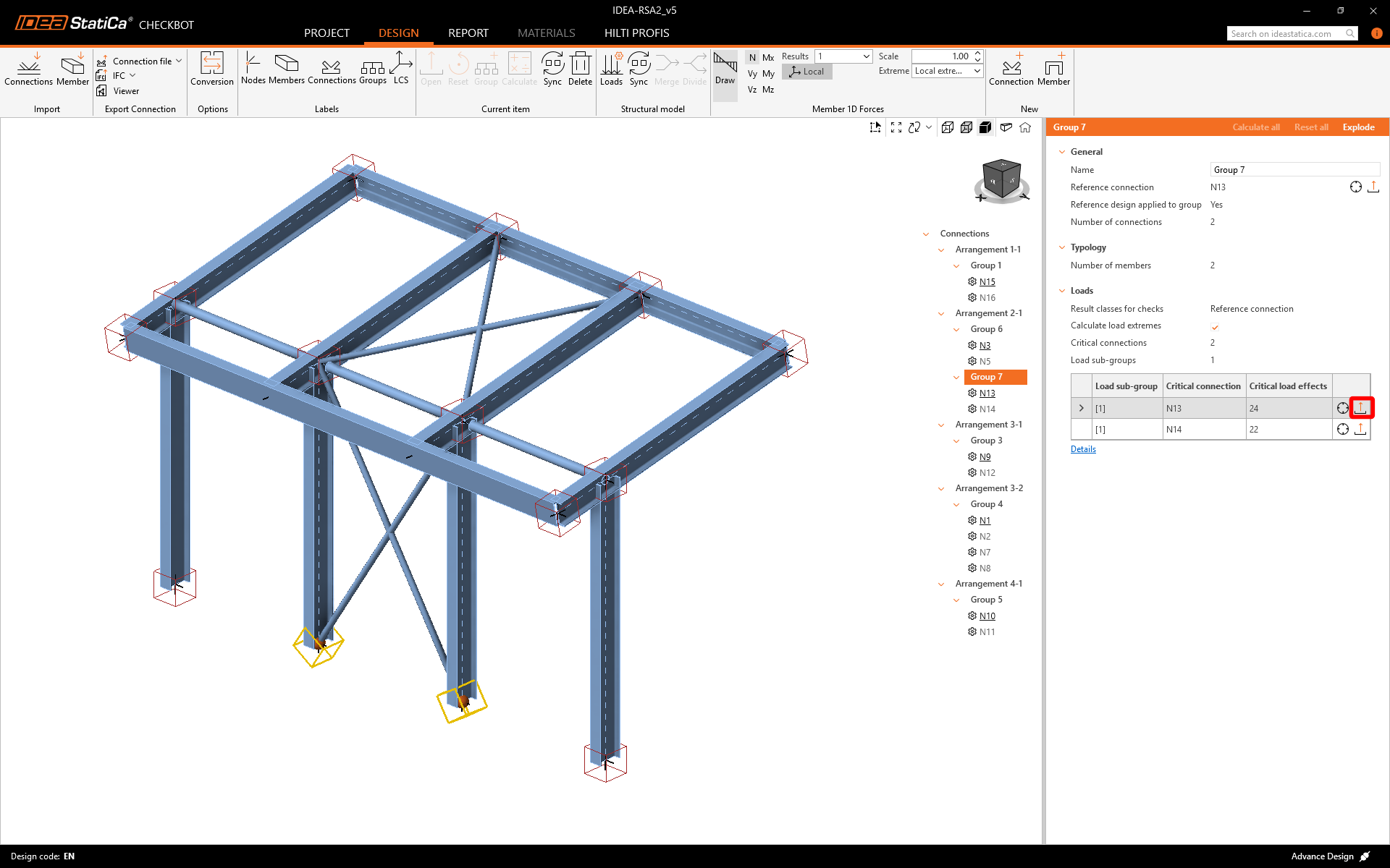
Before designing and analyzing the connections, you can activate Calculate load extremes for any group. This allows you to design and check the connections faster for only critical load effects.
Design
Click on Open to start designing, code-checking, and reporting. The imported connection is opened in the IDEA StatiCa Connection application.
In this tutorial, we are going to use the Connection Library to generate a connection. Select Propose, and IDEA StatiCa will put forward possible solutions for the current geometry.
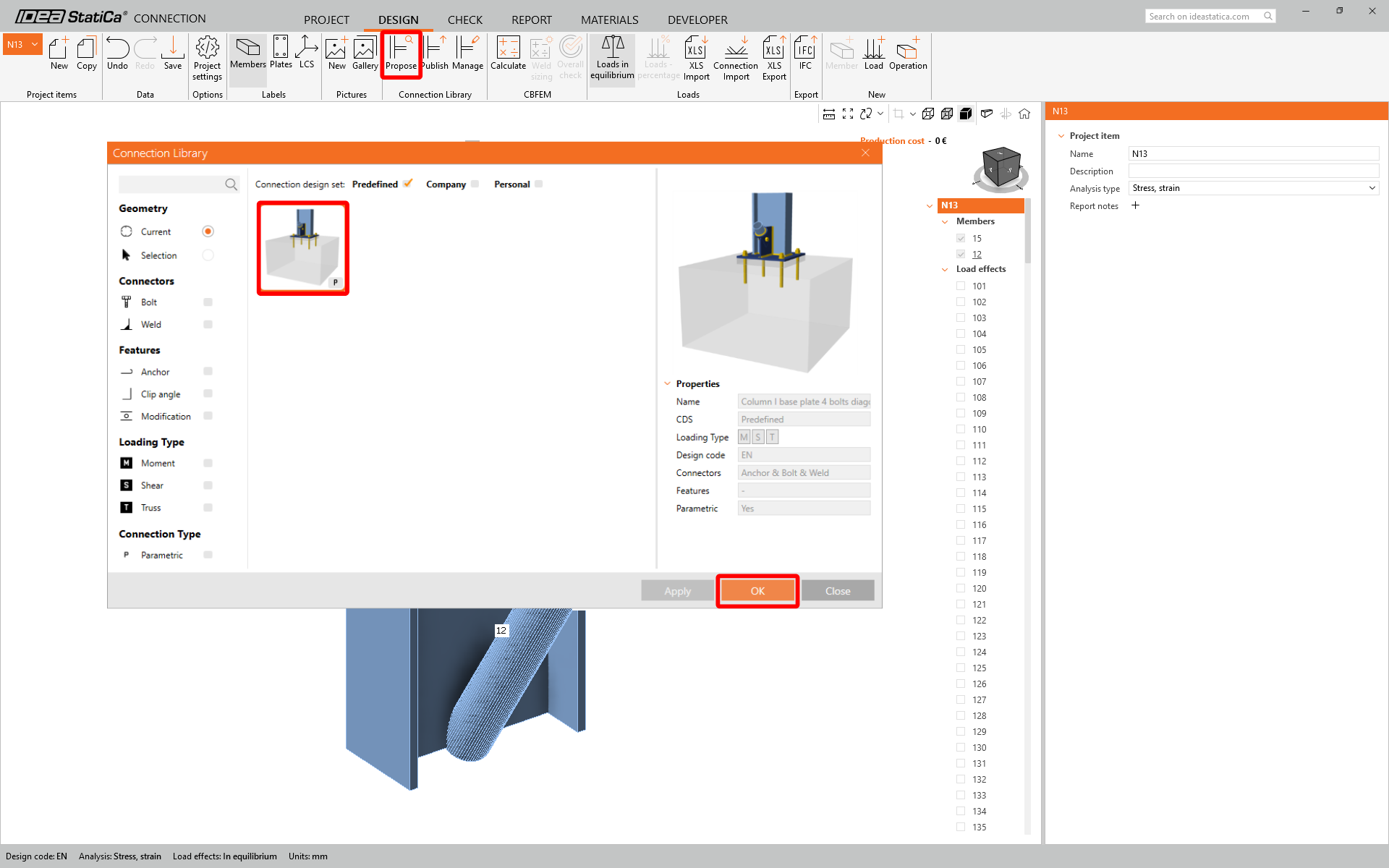
Confirm Propose connection - convection dialog

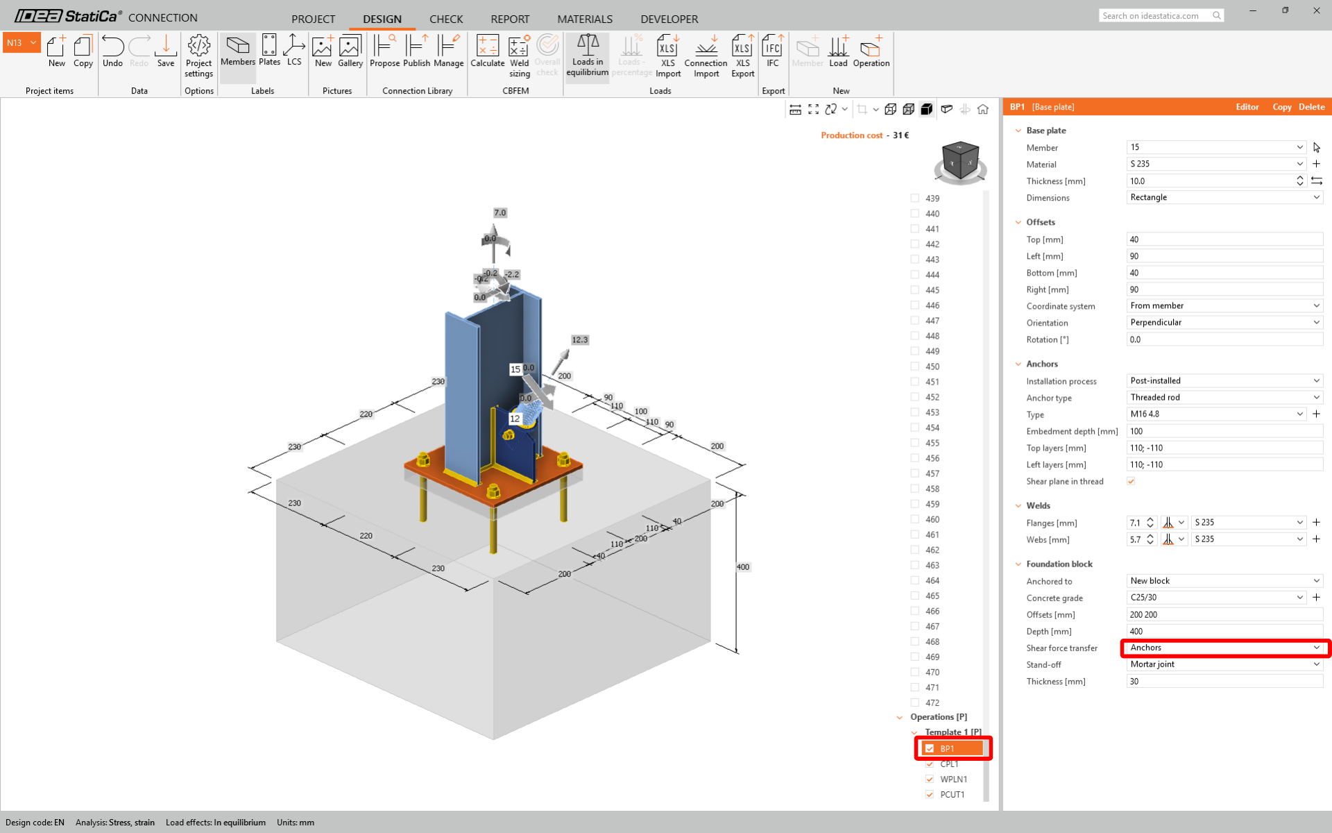
In Member 12, change Model type to N-Vy-Vz

Under BP1 change the Shear force transfer type to Anchors.
Code-check and Report
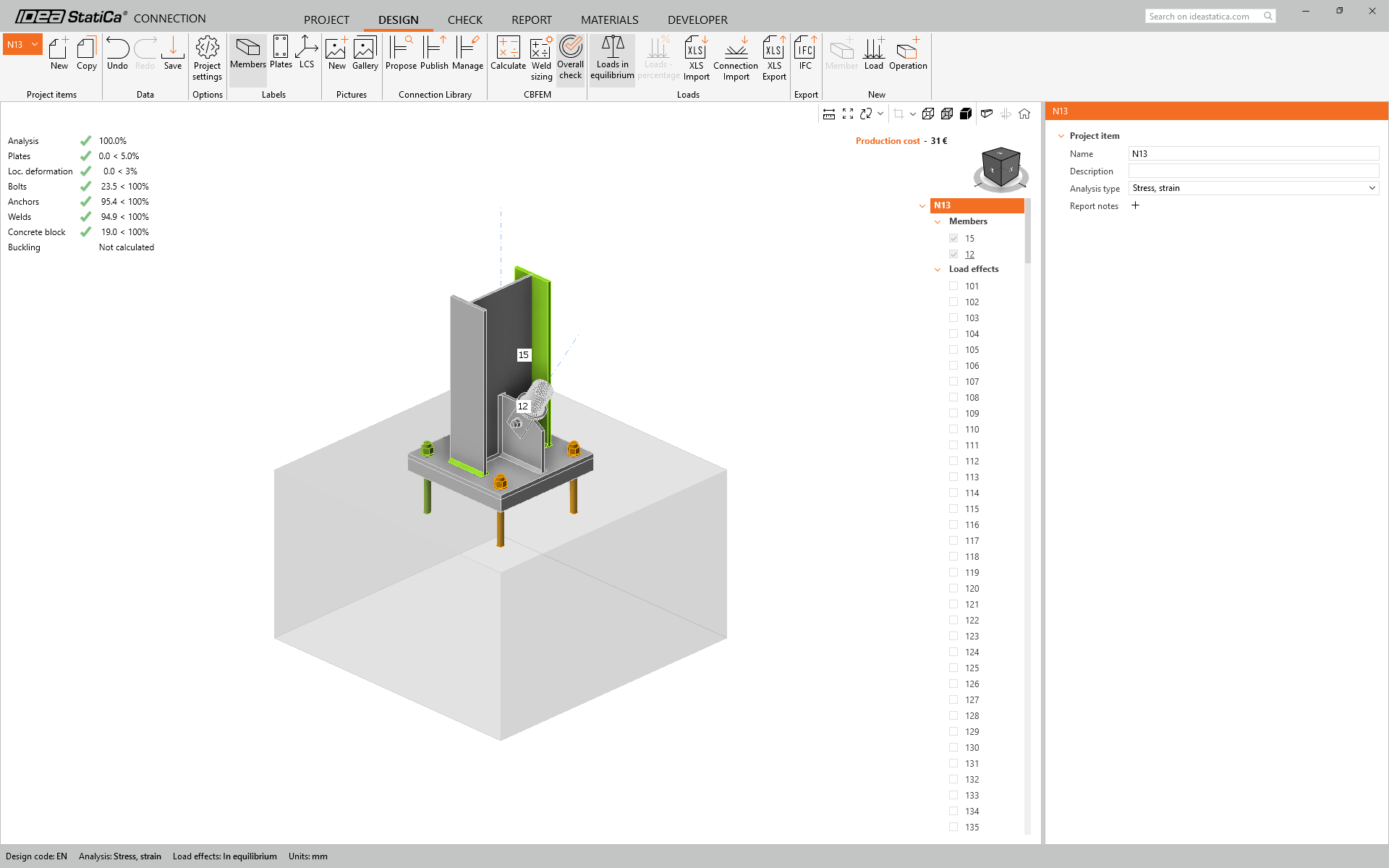
Now run a code-check using the Calculate icon in the CBFEM panel from the top ribbon. Within IDEA StatiCa Connection, you can carry out many different types of analysis and code checks.

You can go to the Check tab to review the results in detail for both the FEM analysis and the code checks.
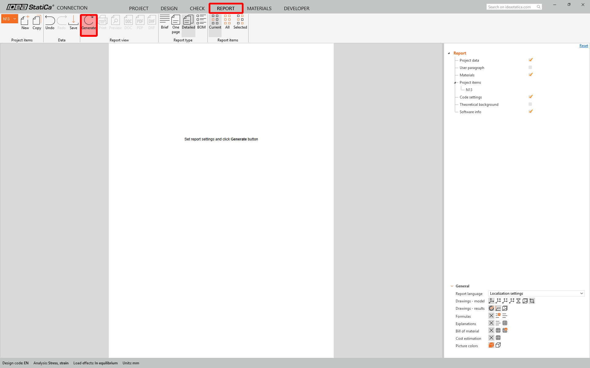
Once the code-check is finished in the Report tab, you can create the report containing results and diagrams for your connection model.
Save this connection and switch back to the Checkbot window (you can keep the Connection window open).
To verify the structural integrity of the imported connections, select the entire group, unselect Calculate load extremes, right-click on a Group 7, and click Calculate all. This triggers a batch analysis for all selected items.
Note: For complex connections, it is advisable to perform the final calculation using the entire set of load effects to ensure all loads defined in the global structural model are clearly accounted for.
For more detailed information, please refer to this article.

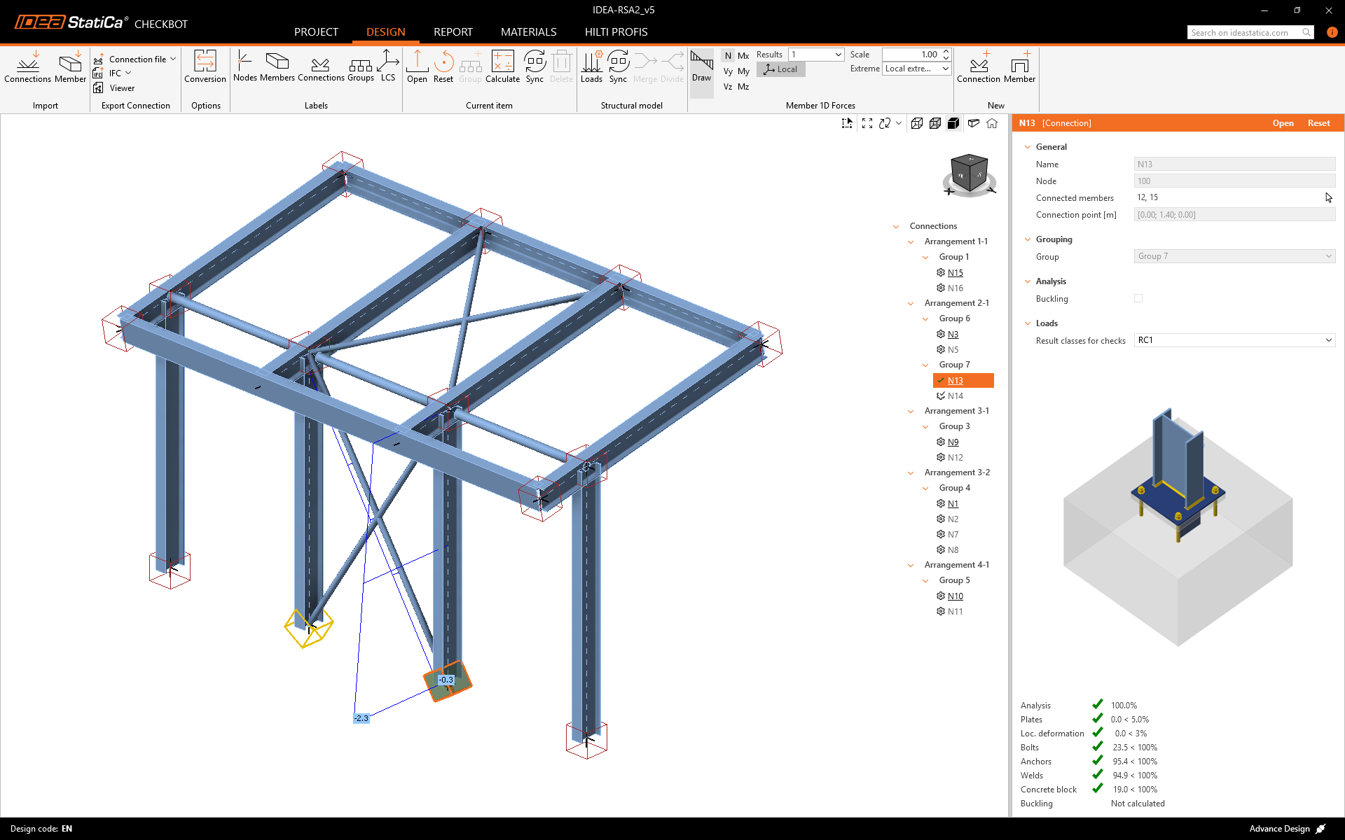
In Checkbot, you will see a green tick next to the connection and the node box filled with green color. This means that the connection has passed all code checks. In the Connection panel, you can also see a representation of the connection and a summary of the code-check results.
You can see that only one connection has passed the respective code-check, while the remaining connections have yet to be designed.
You have successfully linked Advance Design with IDEA StatiCa Connection via Checkbot.