See the webinar recording from Connection Wednesdays – 3 most common traps in connection design where we presented three approaches and explains the correct one.
In the first approach, our goal was to add a new member to model the stub. Although it may seem appropriate for some beginner users, it is definitely not (see When to use a stiffening member?).
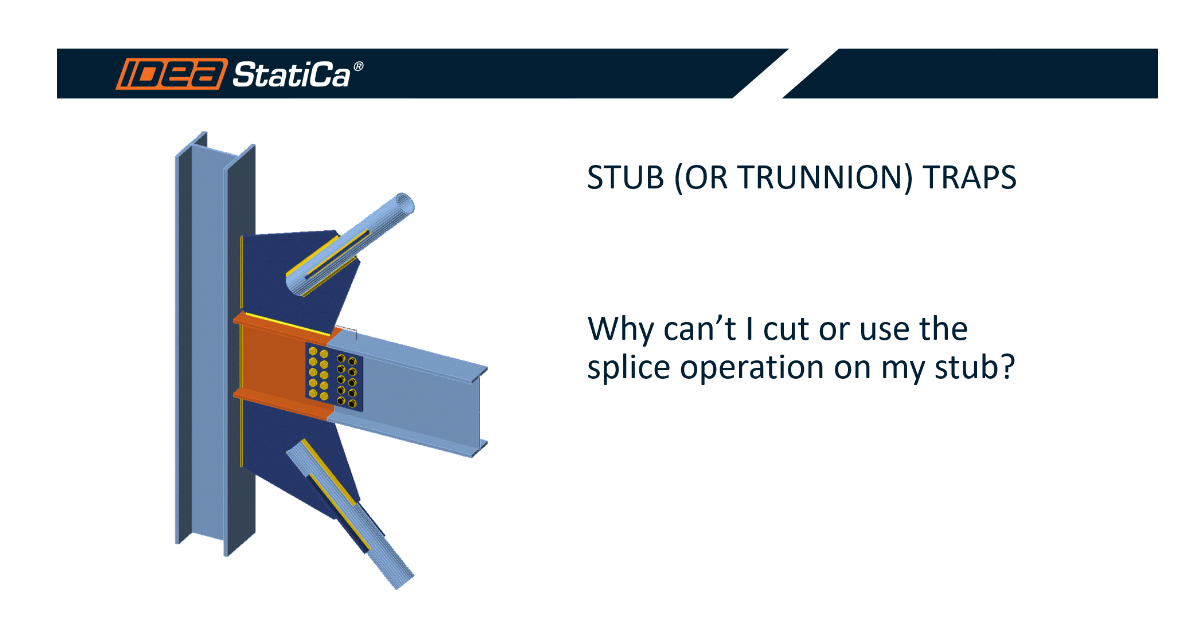
The second approach was to use the dedicated operation for a stub, which could be correct. Nevertheless, there appeared a new issue with replacing the end plate with a splice.
The third and correct approach how to add a stub and connect it with a splice is to use a stiffening member and apply a splice operation on it.
Another example of how to correctly define a stub was presented in Connection Wednesdays – Common rookie mistakes on steel joints webinar, where we fixed a stub model reporting singularities.
In case you need to model a complex stub that connects a member and a part of a beam and you can not find it in the predefined operations, you can always compose it by yourself using a variety of basic operations – stiffening plate, stiffening member, cut of plate, general weld, etc. This takes a bit more time but allows you to create any design needed.
Watch our webinar recording to learn how to utilize these operations for your projects:
Learn how to use IDEA StatiCa effectively with our self-paced e-learning courses
Start learning