Přípoje na jednom plechu ve smyku (AISC)
Tento ověřovací příklad byl připraven Markem D. Denavitem a Kaylou Truman-Jarrell v rámci společného projektu University of Tennessee a IDEA StatiCa.
1 Popis
V této části je uvedeno porovnání výsledků metody konečných prvků založené na komponentách (CBFEM) s tradičními výpočetními metodami používanými v praxi v USA pro přípoje na jednom plechu ve smyku. Schéma zkoumaného přípoje je uvedeno na obr. 1.
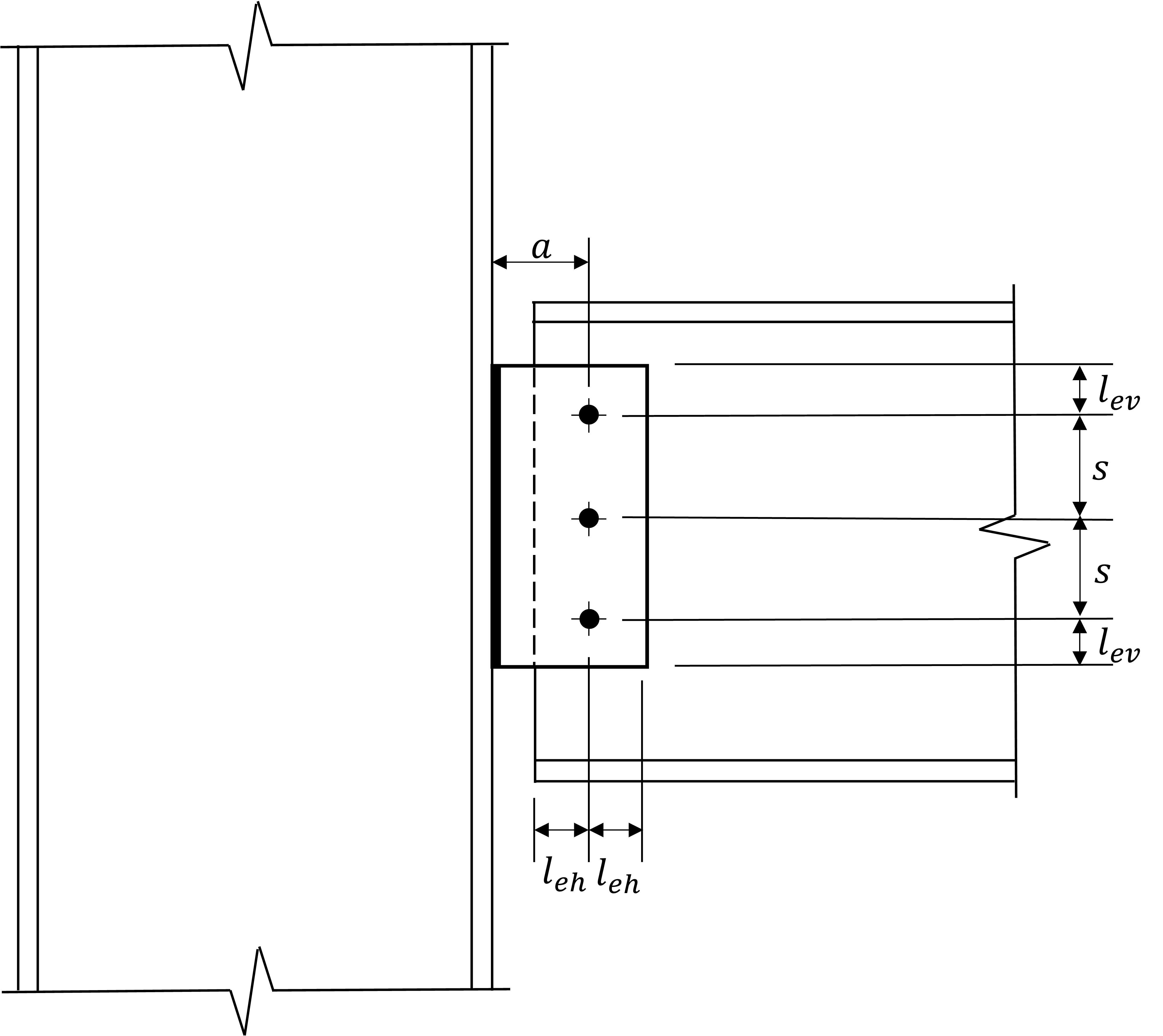
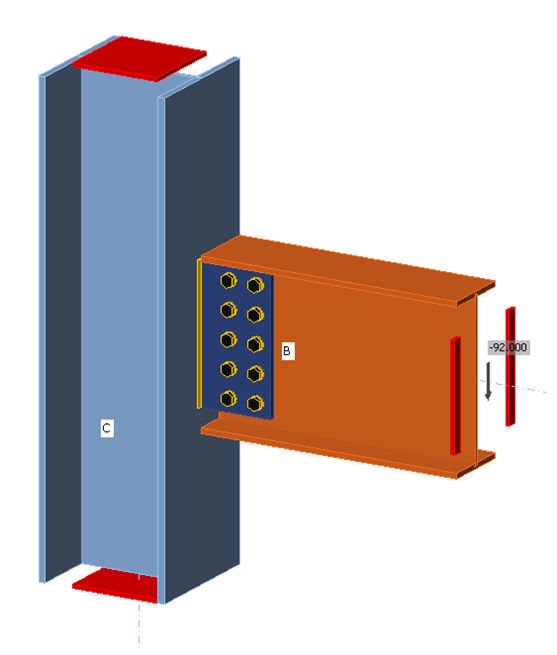
Obr. 1 Schéma přípoje na jednom plechu ve smyku.
Tradiční výpočetní metody použité v této práci vycházejí z doporučení uvedených v části 10 příručky AISC Manual (2017). V části 10 příručky AISC Manual jsou uvedeny dva přístupy k návrhu přípojů na jednom plechu ve smyku. První, pro „konvenční" konfigurace, nabízí určitá zjednodušení, pokud jsou splněny určité rozměrové požadavky. Druhý, pro „rozšířené" konfigurace, je obecněji použitelný, avšak bez zjednodušení povolených pro návrh konvenčních konfigurací. Konkrétně konvenční konfigurace musí mít jeden svislý řad 2 až 12 šroubů, vzdálenost mezi řadou šroubů a linií svaru, a, musí být nejvýše 3,5 in., šrouby musí být ve standardních otvorech nebo krátkých drážkách kolmých na reakci prvku, svislá vzdálenost od okraje, lev, musí splňovat minimální požadavky na okrajové vzdálenosti dle tabulky J3.4 normy AISC Specification (2016), vodorovná vzdálenost od okraje, leh, musí být větší nebo rovna 2d, kde d je průměr šroubu, a buď tloušťka plechu, tp, nebo tloušťka stojiny nosníku, tw, musí splňovat maximální požadavky na tloušťku.
Hlavním zjednodušením návrhu přípojů splňujících tyto požadavky je, že únosnost skupiny šroubů lze posoudit takto: únosnost šroubů ve smyku se ověří pomocí excentricity uvedené v tabulce 10-9 příručky AISC Manual (2017) a otlačení a vytržení se ověří za předpokladu, že reakce je přenášena soustředěně. Toto zjednodušení odstraňuje potřebu uvažovat vytržení v excentricky zatížené skupině šroubů. Pro výpočty rozšířené konfigurace, kde je vytržení zohledněno při stanovení únosnosti excentricky zatížené skupiny šroubů, jsou použity dvě různé metody. První metodou je běžně používaná konzervativní aproximace známá jako metoda „poison bolt". V této metodě se únosnost excentricky zatížené skupiny šroubů stanoví identifikací nejmenší možné únosnosti pro kterýkoli ze šroubů v jakémkoli směru síly a následným využitím této hodnoty únosnosti ve spojení s hodnotou C z tabulek v části 7 příručky AISC Manual (2017). Hodnoty C uvedené v tabulkách jsou vypočteny metodou okamžitého středu otáčení (IC). Druhou metodou je použití modifikované metody okamžitého středu otáčení vyvinuté Denavitem et al. (2021), ve které je vytržení explicitně zohledněno v iteračním postupu pro stanovení únosnosti skupiny šroubů.
Kromě únosnosti skupiny šroubů jsou pro konvenční konfigurace ověřovány také smykové přetvoření plechu, smykové porušení plechu, blokové smykové porušení plechu a smyk svaru. Další posouzení pro rozšířené konfigurace zahrnují posouzení na ohybové porušení, interakční únosnost plechu a boulení plechu.
Všechny tradiční výpočty byly provedeny v souladu s ustanoveními pro návrh na základě součinitelů zatížení a únosnosti (LRFD) dle normy AISC Specification (2016).
Výsledky CBFEM byly získány z IDEA StatiCa verze 21.0. Příklad modelu je zobrazen na obr. 2. Maximální přípustná zatížení byla stanovena iterativně úpravou vstupního zatížení na hodnotu, kterou program považuje za bezpečnou, ale při jejím malém zvýšení (např. o 0,1 kip) by ji program považoval za nebezpečnou. Ve všech modelech byl podepřený nosník přiřazen k typu modelu „N-Vz-My", aby bylo zajištěno rovinné chování. Pokud není uvedeno jinak, byly síly definovány tak, aby bod nulového momentu byl umístěn v linii svaru, což odpovídá předpokladu návrhových metod uvedených v části 10 příručky AISC Manual (2017).

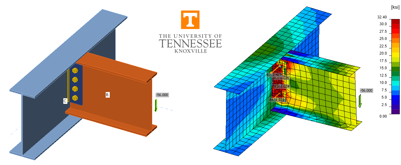
Obr. 2 Přípoj na jednom plechu ve smyku modelovaný v IDEA StatiCa.
2 Únosnost skupiny šroubů
Nejprve jsou zkoumány přípoje, u nichž únosnost skupiny šroubů určuje únosnost přípoje. Pro tato porovnání je sloup W14x90 a podepřený nosník, který je připojen k přírubě sloupu, je W18x50. Oba odpovídají ASTM A992 (Fy = 50 ksi, Fu = 65 ksi). Plech je 15 in. vysoký (s = 3 in., lev = 1,5 in.), tloušťky 1/2 in. a odpovídá ASTM A36 (Fy = 36 ksi, Fu = 58 ksi). Každý svislý řad šroubů má (5) šroubů průměru 3/4 in. A325 se závity nevyloučenými ze smykové roviny a vodorovnou vzdáleností od okraje, leh = 2,0 in. Svar byl koutový svar 5/16 in. na obou stranách v souladu s pravidlem (5/8)tp uvedeným v části 10 příručky AISC Manual (2017). Vzdálenost od linie svaru k řadě šroubů, a, byla měněna od 2 in. do 5 in. (obr. 3). Upozorňujeme, že tento přípoj splňuje požadavky pro konvenční konfiguraci při a ≤ 3,5 in.

Obr. 3 Variace hodnoty 'a' v modelu IDEA StatiCa.
Závislost smykové únosnosti přípojů na vzdálenosti a je uvedena na obr. 4. Smykové porušení šroubů bylo rozhodujícím mezním stavem pro všechny hodnoty a a všechny metody výpočtu. Výsledky IDEA StatiCa dobře odpovídají tradičním výpočtům pro rozšířenou konfiguraci. Tam, kde je to relevantní, tradiční výpočty pro konvenční konfiguraci poskytují poněkud větší smykovou únosnost. Důvodem je, že pro konvenční konfigurace je povoleno uvažovat sníženou excentricitu a/2 dle tabulky 10-9 příručky AISC Manual (2017). Excentricita skupiny šroubů je pro výpočty rozšířené konfigurace rovna a. Excentricita skupiny šroubů je rovněž rovna a pro IDEA StatiCa, protože bod nulového momentu byl definován v linii svaru. Metoda poison bolt a modifikovaná metoda IC poskytují stejné výsledky, což naznačuje, že vytržení nebylo rozhodující pro žádný šroub (tj. plech a stojina nosníku byly dostatečně tlusté a rozteče šroubů a okrajové vzdálenosti byly dostatečně velké).
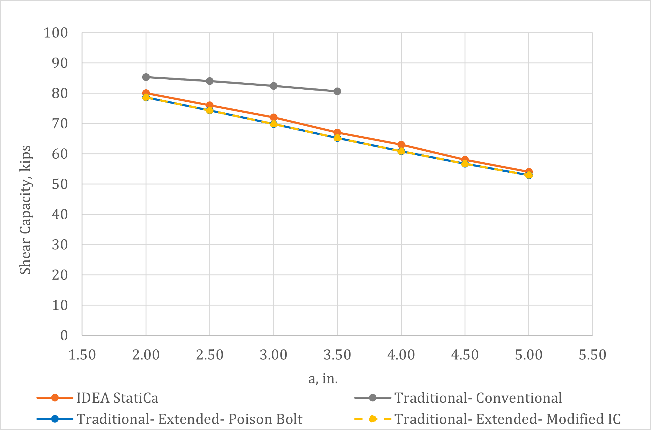
Obr. 4 Smyková únosnost přípoje na jednom plechu ve smyku v závislosti na 'a'.
Závislost smykové únosnosti na vzdálenosti a je uvedena na obr. 5 pro přípoje se stejnými vlastnostmi, jak bylo popsáno výše, ale se dvěma svislými řady šroubů (obr. 6) a leh = 1,5 in. Vodorovná rozteč mezi svislými řady šroubů byla 3 in. Tyto přípoje jsou rozšířenou konfigurací bez ohledu na hodnotu a, protože mají více než jeden svislý řad šroubů. Opět bylo smykové porušení šroubů rozhodujícím mezním stavem pro všechny hodnoty a a všechny metody a výsledky IDEA StatiCa dobře odpovídají tradičním výpočtům.
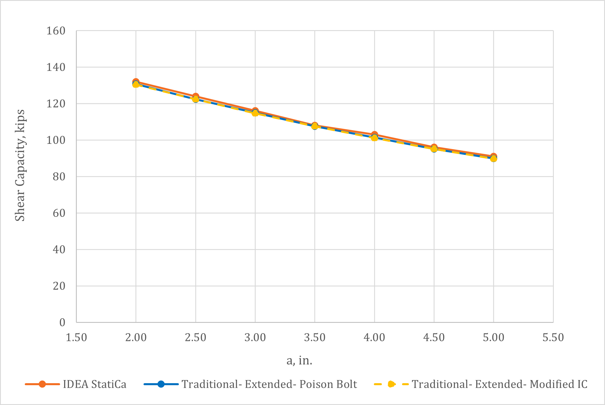
Obr. 5 Smyková únosnost rozšířené konfigurace se dvěma řady šroubů v závislosti na 'a'.
Obr. 6 Rozšířená konfigurace se 2 řady šroubů modelovaná v IDEA StatiCa.
3 Tloušťka plechu
Změna tloušťky plechu umožňuje, aby byl rozhodující širší rozsah mezních stavů, včetně otlačení a vytržení v otvorech pro šrouby a smykového přetvoření a porušení plechu. Pro tato porovnání je sloup W14x90 a podepřený nosník, který je připojen k přírubě sloupu, je W18x130. Oba odpovídají ASTM A992 (Fy = 50 ksi, Fu = 65 ksi). Plech je 14 in. vysoký (s = 3 in., lev = 1 in.) a odpovídá ASTM A572 Gr. 50 (Fy = 50 ksi, Fu = 65 ksi). Tloušťka plechu se v těchto analýzách mění od 3/16 in. do 3/4 in. Je zde jeden svislý řad (5) šroubů průměru 3/4 in. A490 se závity nevyloučenými ze smykové roviny a vodorovnou vzdáleností od okraje, leh = 1,5 in. Koutové svary byly provedeny na obou stranách plechu s velikostí měnící se s tloušťkou plechu v souladu s pravidlem (5/8)tp uvedeným v části 10 příručky AISC Manual (2017). Vzdálenost od linie svaru k řadě šroubů, a, byla 3,0 in. Tyto přípoje splňují požadavky pro konvenční konfiguraci pro tloušťky plechu menší nebo rovné 7/16 in.
Závislost smykové únosnosti přípojů na tloušťce plechu je uvedena na obr. 7 a rozhodující mezní stavy jsou uvedeny v tabulce 1. Nejpozoruhodnějším výsledkem je, že tradiční výpočty pro rozšířenou konfiguraci metodou poison bolt vykazují výrazně nižší únosnosti než ostatní metody. Metoda poison bolt, při níž je nejnižší možná únosnost jakéhokoli šroubu považována za únosnost každého šroubu, může být velmi konzervativní. Přesto se v praxi používá pro posouzení excentricky zatížených skupin šroubů, kde může být rozhodující vytržení. Pro tento přípoj je únosnost všech šroubů založena na únosnosti spodního šroubu na vytržení s využitím okrajové vzdálenosti lev = 1 in., což vede k čisté vzdálenosti lc = 0,594 in. V IDEA StatiCa a modifikované metodě IC je únosnost každého jednotlivého šroubu založena na čisté vzdálenosti ve směru síly pro daný šroub. Například při limitní smykové únosnosti přípoje s plechem tloušťky 1/4 in. je čistá vzdálenost pro spodní šroub vypočtená programem IDEA StatiCa lc = 1,240 in. na základě úhlu zatížení v šroubu (obr. 8b). Únosnost na vytržení je úměrná čisté vzdálenosti, takže únosnost šroubů dle IDEA StatiCa je výrazně větší než předpokládá metoda poison bolt.
U přípojů s tenčími plechy byl plech rozhodující jak v IDEA StatiCa, tak v tradičních výpočtech (s výjimkou těch využívajících metodu poison bolt). V IDEA StatiCa se však plastická přetvoření soustředila v otvorech horního a zejména spodního šroubu (obr. 8). To je v kontrastu s předpokládanou rovinou smykového porušení používanou v tradičních výpočtech (tj. svislá linie procházející středy šroubů). Navzdory rozdílům v chování byla výsledná smyková únosnost blízká, přičemž IDEA StatiCa poskytovala mírně nižší smykové únosnosti pro přípoje s tenčími plechy.
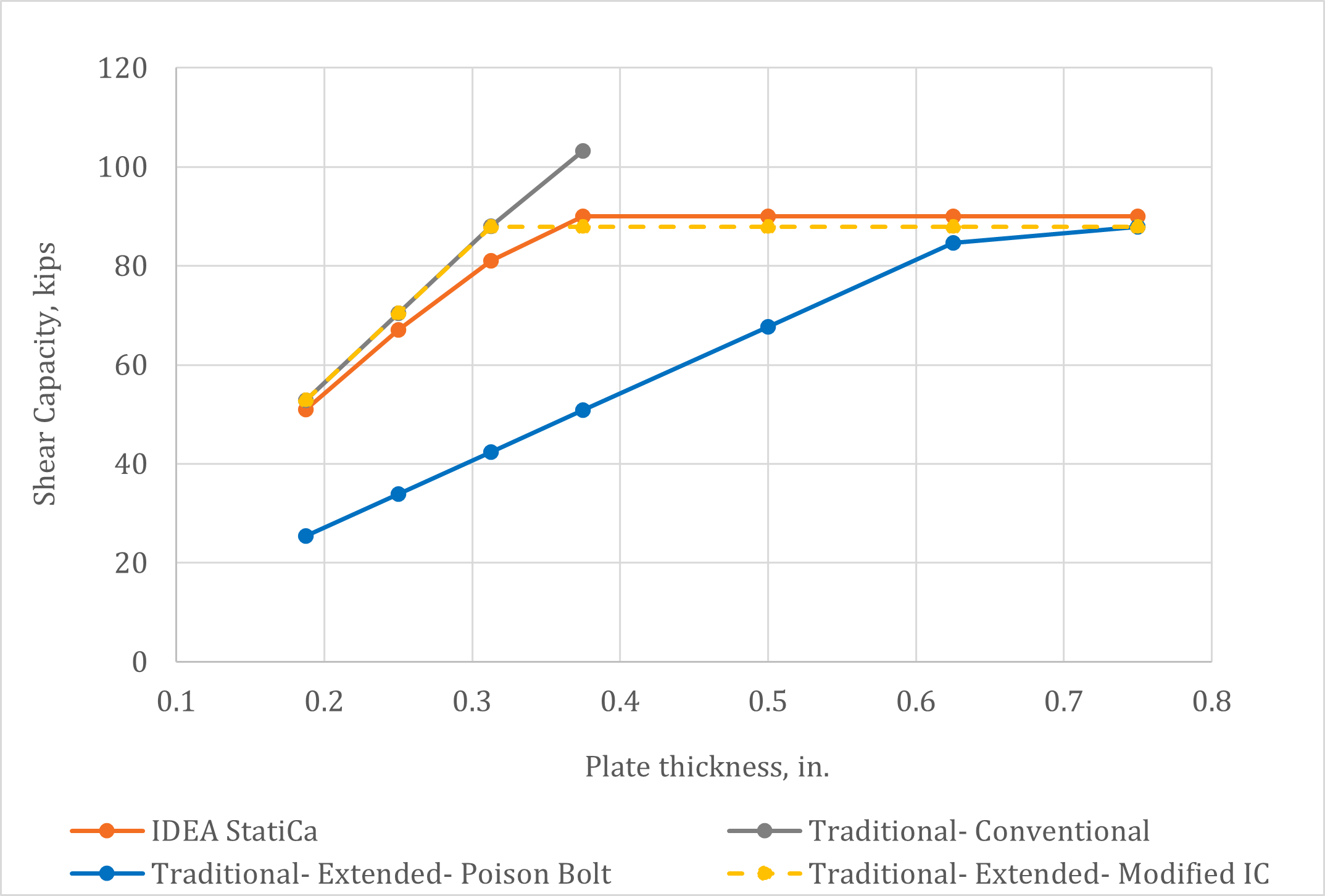
Obr. 7 Smyková únosnost přípoje na jednom plechu ve smyku v závislosti na tloušťce plechu.
Tabulka 1. Rozhodující mezní stav pro výsledky uvedené na obr. 7
| Tloušťka plechu | IDEA StatiCa | Tradiční Konvenční | Tradiční rozšířená (Poison Bolt) | Tradiční rozšířená (Modifikovaná IC) |
| 3/16 in. | Přetvoření plechu | Smykové porušení plechu | Skupina šroubů | Smykové porušení plechu |
| 1/4 in. | Přetvoření plechu | Smykové porušení plechu | Skupina šroubů | Smykové porušení plechu |
| 5/16 in. | Přetvoření plechu | Smykové porušení plechu | Skupina šroubů | Skupina šroubů |
| 3/8 in. | Smykové porušení šroubů | Smykové porušení šroubů | Skupina šroubů | Skupina šroubů |
| 1/2 in. | Smykové porušení šroubů | n/a | Skupina šroubů | Skupina šroubů |
| 5/8 in. | Smykové porušení šroubů | n/a | Skupina šroubů | Skupina šroubů |
| 3/4 in. | Smykové porušení šroubů | n/a | Skupina šroubů | Skupina šroubů |

Obr. 8 Podrobné výsledky pro přípoj s tloušťkou plechu 1/4 in.
4 Další konfigurace rámování
Přípoje na jednom plechu ve smyku se používají pro různé konfigurace rámování. Tato část zkoumá dvě další konfigurace: jednu, kde je podepřený nosník připojen ke stojině sloupu, a druhou, kde je podepřený nosník připojen ke stojině průvlaku.
V případě podepřeného nosníku připojeného ke stojině sloupu (obr. 9) je sloup W27x114 a podepřený nosník je W18x50. V případě podepřeného nosníku připojeného ke stojině průvlaku (obr. 11) je průvlak W21x55 a podepřený nosník je W18x46. Všechny válcované profily odpovídají ASTM A992 (Fy = 50 ksi, Fu = 65 ksi). V obou případech je plech 13 in. vysoký (s = 3 in., lev = 2 in.), tloušťky 3/8 in. a odpovídá ASTM A36 (Fy = 36 ksi, Fu = 58 ksi). Přípoje mají jeden svislý řad (4) šroubů průměru 3/4 in. A325 se závity nevyloučenými ze smykové roviny a vodorovnou vzdáleností od okraje, leh = 2 in. Svar byl koutový svar 5/16 in. na obou stranách plechu. Vzdálenost od linie svaru k řadě šroubů, a, byla měněna od 3 in. do 5,5 in.
Závislost smykové únosnosti přípojů na vzdálenosti a je uvedena na obr. 10 pro případ podepřeného nosníku připojeného ke stojině sloupu a na obr. 12 pro případ podepřeného nosníku připojeného ke stojině průvlaku. Smykové porušení šroubů bylo rozhodujícím mezním stavem pro všechny hodnoty a a všechny metody v obou konfiguracích rámování. Únosnost stanovená z IDEA StatiCa souhlasí s únosností z tradičních výpočtů.
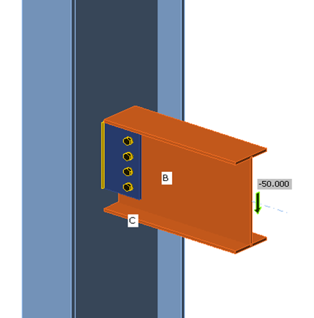
Obr. 9 Model IDEA StatiCa přípoje na jednom plechu ve smyku přivařeného ke slabé ose sloupu.
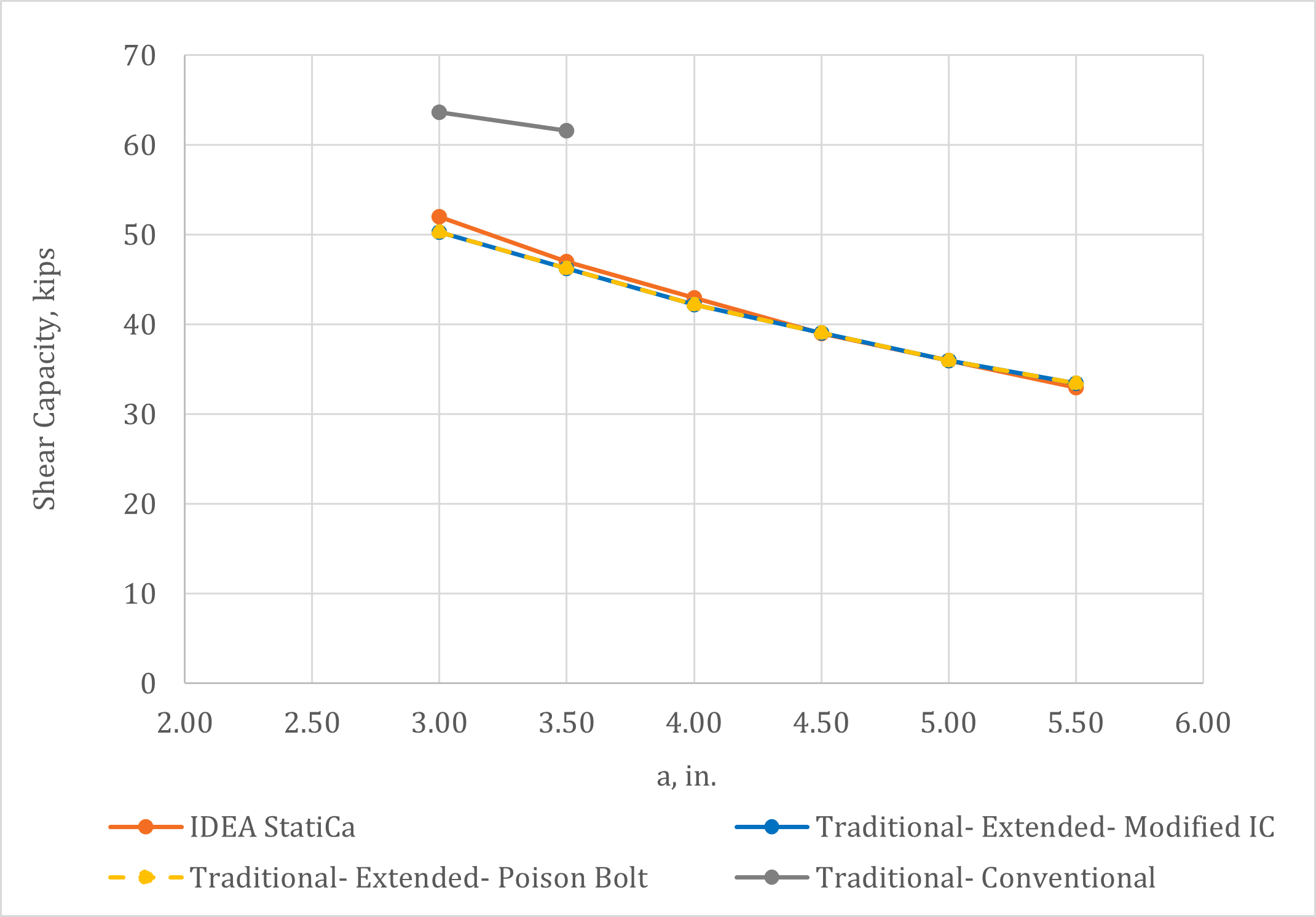
Obr. 10 Smyková únosnost přípoje na jednom plechu ve smyku přivařeného ke slabé ose sloupu v závislosti na 'a'.

Obr. 11 Model IDEA StatiCa přípoje na jednom plechu ve smyku přivařeného ke stojině nosníku.

Obr. 12 Smyková únosnost přípoje na jednom plechu ve smyku přivařeného ke stojině nosníku v závislosti na 'a'.
5 Poloha bodu nulového momentu
Návrhová metodika pro přípoje na jednom plechu ve smyku v části 10 příručky AISC Manual (2017) předpokládá, že bod nulového momentu se nachází v linii svaru. V souladu s tím všechny dosavadní analýzy IDEA StatiCa v tomto dokumentu využívaly ekvivalentní předpoklad pro polohu na prvku od uzlu, kde je aplikováno zatížení, X. Nicméně lze zvolit i jiné polohy bodu nulového momentu, zejména pokud je volba provedena konzistentně s polohou kloubu v modelu konstrukce pro statickou analýzu rámu.
Byly provedeny analýzy ke zkoumání vlivu polohy bodu nulového momentu. Pro tyto analýzy je sloup W14x90 a podepřený nosník, který je připojen k přírubě sloupu, je W18x143. Oba odpovídají ASTM A992 (Fy = 50 ksi, Fu = 65 ksi). Plech je 14 in. vysoký (s = 3 in., lev = 1 in.), tloušťky 3/8 in. a odpovídá ASTM A572 Gr. 50 (Fy = 50 ksi, Fu = 65 ksi). Je zde jeden svislý řad (5) šroubů průměru 3/4 in. A490 se závity vyloučenými ze smykové roviny a vodorovnou vzdáleností od okraje, leh = 1 in. Koutové svary byly provedeny na obou stranách plechu s velikostí měnící se s tloušťkou plechu v souladu s pravidlem (5/8)tp uvedeném v části 10 příručky AISC Manual (2017). Vzdálenost od linie svaru k řadě šroubů, a, byla 9 in.
Závislost smykové únosnosti na vzdálenosti X (měřené od osy sloupu k poloze bodu nulového momentu) je uvedena na obr. 13. Rozhodujícím mezním stavem dle IDEA StatiCa bylo vytržení šroubu pro x ≤ 16 in. a únosnost svaru pro větší hodnoty X. Rozhodujícími mezními stavy pro tradiční výpočty metodou modifikované IC byly únosnost skupiny šroubů pro x < 17 in. a smykové porušení plechu pro větší hodnoty X. Rozhodujícím mezním stavem pro tradiční výpočty metodou poison bolt byla únosnost skupiny šroubů pro všechny hodnoty X. Je zajímavé poznamenat, že výsledky IDEA StatiCa byly v tomto porovnání blízké výsledkům metody poison bolt. V těchto případech je směr síly v rozhodujícím šroubu blízký nejhorší podmínce použité v metodě poison bolt (obr. 14).
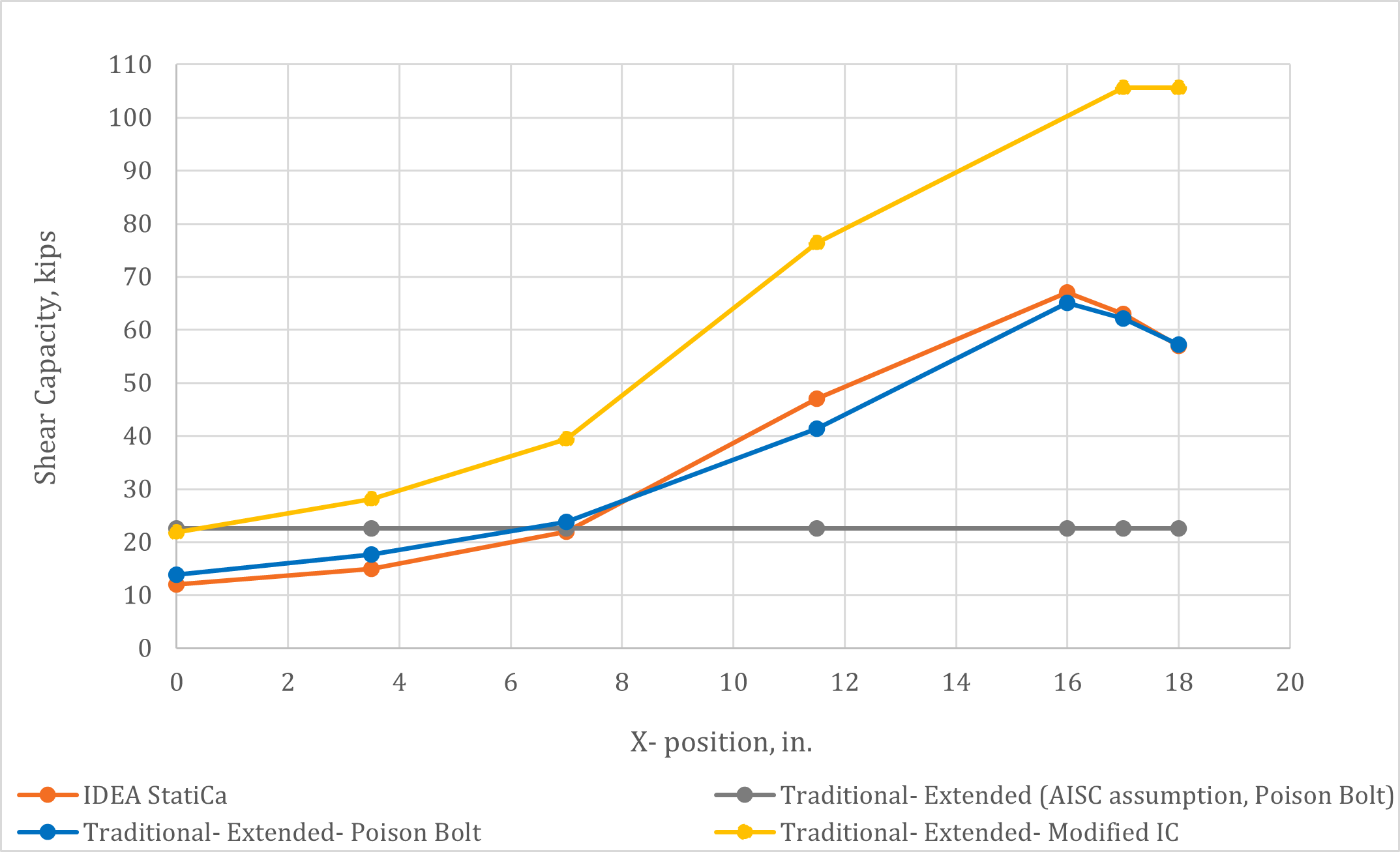
Obr. 13 Smyková únosnost přípoje na jednom plechu ve smyku v závislosti na poloze bodu nulového momentu

Obr. 14 Podrobné výsledky pro přípoj s bodem nulového momentu umístěným v linii svaru.
6 Analýza tuhosti
Kromě požadavků na únosnost musí přípoje na jednom plechu ve smyku splňovat také požadavky na rotační kapacitu. Článek B3.4a normy AISC Specification (2016) uvádí, že „kloubový přípoj musí mít dostatečnou rotační kapacitu pro přenesení požadované rotace stanovené analýzou konstrukce." Pro tradiční výpočty je tento požadavek splněn omezením maximální tloušťky plechu a stojiny nosníku popsaným v části 10 příručky AISC Manual (2017). V IDEA StatiCa lze tento požadavek splnit provedením analýzy tuhosti.
Rotační kapacity ze série analýz přípojů s různou tloušťkou plechu jsou uvedeny na obr. 15. Pro tyto analýzy je sloup W14x90 a podepřený nosník, který je připojen k přírubě sloupu, je W18x130. Oba odpovídají ASTM A992 (Fy = 50 ksi, Fu = 65 ksi). Plech je 15 in. vysoký (s = 3 in., lev = 1,5 in.) a odpovídá ASTM A572 Gr. 50 (Fy = 50 ksi, Fu = 65 ksi). Je zde jeden svislý řad (5) šroubů průměru 7/8 in. A325 se závity nevyloučenými ze smykové roviny a vodorovnou vzdáleností od okraje, leh = 1,5 in. Koutové svary byly provedeny na obou stranách plechu s velikostí měnící se s tloušťkou plechu v souladu s pravidlem (5/8)tp uvedeným v části 10 příručky AISC Manual (2017). Vzdálenost od linie svaru k řadě šroubů, a, byla 3 in. Tyto přípoje splňují požadavky pro konvenční konfiguraci a rotační kapacitu, protože všechny tloušťky plechu jsou menší nebo rovné 1/2 in. (tabulka 10-9 příručky AISC Manual).
Analýzy byly provedeny s použitím typu analýzy 'ST' (tuhost). Na rozdíl od předchozích analýz byly tyto modely zatíženy ohybovými momenty kolem hlavní osy nosníku. Rotační kapacita byla nezávislá na velikosti aplikovaného zatížení.
Dle článku B3.4a normy AISC Specification (2016) je požadovaná rotační kapacita stanovena ze statické analýzy a závisí na konfiguraci rámování a zatíženích. Hodnota 0,03 rad nebo 30 mrad je obecně přijímána jako přiměřená horní mez pro rotaci konce nosníku a omezení tloušťky plechu v části 10 příručky AISC Manual (2017) byla kalibrována tak, aby tuto horní mez splňovala (Muir a Thornton 2011). Rotační kapacity uvedené na obr. 15 jsou menší než 30 mrad, přestože splňují požadavky na tloušťku plechu. Tyto hodnoty mohou být stále přijatelné pro širokou škálu případů, kde je rotace konce nosníku menší než horní mez, avšak je také možné, že analýza tuhosti v IDEA StatiCa plně nezachycuje tažnost přípojů.

Obr. 15 Rotační kapacita v závislosti na různé tloušťce plechu.
7 Shrnutí
Tato studie porovnávala návrh přípojů na jednom plechu ve smyku tradičními výpočetními metodami používanými v praxi v USA a programem IDEA StatiCa. Klíčová zjištění studie zahrnují:
- Dostupná únosnost přípojů na jednom plechu ve smyku dle IDEA StatiCa dobře souhlasí s tradičními výpočty metodou pro rozšířené konfigurace.
- Dostupná únosnost dle IDEA StatiCa byla shledána konzervativní v porovnání s tradičními výpočty metodou pro konvenční konfigurace, která v některých případech předpokládá sníženou excentricitu.
- IDEA StatiCa stanovuje čistou vzdálenost pro každý šroub individuálně pro posouzení vytržení, což vede k odpovídajícímu snížení únosnosti při malých okrajových vzdálenostech.
- IDEA StatiCa umožňuje zkoumání různých předpokládaných poloh bodu nulového momentu.
- Analýzu tuhosti v IDEA StatiCa lze použít k posouzení požadavků na rotační kapacitu dle článku B3.4a normy AISC Specification. Výsledky však byly shledány konzervativní v porovnání s návrhových pravidly uvedenými v příručce AISC Manual pro zkoumané případy.
8 Literatura
AISC. (2016). Specification for Structural Steel Buildings. American Institute of Steel Construction, Chicago, Illinois.
AISC. (2017). Steel Construction Manual, 15th Edition. American Institute of Steel Construction, Chicago, Illinois.
Denavit, M. D., Franceschetti, N., and Shahan, A. (2021). Investigation of Bearing and Tearout of Steel Bolted Connections. Final Research Report to the American Institute of Steel Construction, Chicago, Illinois.
Muir, L. S., and Thornton, W. A. (2011). "The Development of a New Design Procedure for Conventional Single-Plate Shear Connections." AISC Engineering Journal, 48(2), 141–152.