T-stub přípoje (AISC)
Tento ověřovací příklad byl připraven Markem D. Denavitem a Kaylou Truman-Jarrell v rámci společného projektu University of Tennessee a IDEA StatiCa.
Popis
Tato studie představuje porovnání výsledků metody konečných prvků založené na komponentách (CBFEM) s tradičními výpočetními metodami používanými v praxi v USA pro T-stub přípoje. Schéma zkoumaného přípoje je uvedeno na obr. 1. Hodnocené mezní stavy zahrnují prokluz, interakci tahové a smykové únosnosti šroubů a ohybové plastické přetvoření pásnic T-stub a nosníku. Je zohledněn vliv páčení.
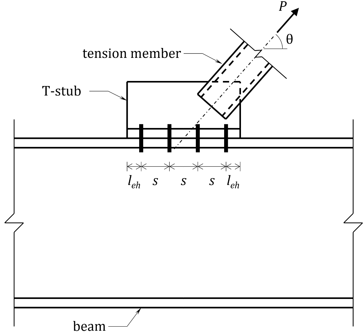
Obr. 1 Schéma T-stub přípoje zkoumaného v této studii
U všech zkoumaných přípojů je nosník širokopásový profil odpovídající ASTM A992 (Fy = 50 ksi a Fu = 65 ksi) a T-stub je sestaven z plechů odpovídajících ASTM A572 Gr. 50 (Fy = 50 ksi a Fu = 65 ksi). Pro zjednodušení posouzení jsou použity koutové svary mezi stojinou a pásnicí T-stub a mezi taženým prvkem a stojinou T-stub. Každý zkoumaný přípoj měl (8) šroubů průměru 3/4 in. (tj. 2 řady po 4 šroubech) ve standardních otvorech s roztečí s = 3 in., okrajovou vzdáleností leh = 1,5 in. a roztečí g = 5,5 in.
Tradiční výpočty byly provedeny v souladu s ustanoveními pro návrh metodou mezních stavů únosnosti (LRFD) dle AISC Specification (2016) s uvažováním páčení popsaného v části 9 AISC Manual (2017).
Výsledky CBFEM byly získány z IDEA StatiCa verze 21.0. Maximální přípustná zatížení byla stanovena iterativně úpravou vstupního zatížení na hodnotu, kterou program vyhodnotí jako bezpečnou, avšak při jejím zvýšení o malou hodnotu (0,1 kip) by program vyhodnotil přípoj jako nevyhovující. Analýzy typu DR mohou pomoci identifikovat maximální přípustná zatížení. Nicméně při vyhodnocení návrhové únosnosti styčníku dochází k určitému přiblížení, proto jsou všechny výsledky v této zprávě založeny na analýzách typu EPS.
Přípoje kritické na prokluz
Prvním zkoumaným mezním stavem je prokluz. Konfigurace tohoto příkladu odpovídá příkladu J.5 z AISC Design Examples v15.1 (AISC, 2019). Další podrobnosti přípoje zahrnují: šrouby skupiny A (např. A325) se závity nevyloučenými ze střihových rovin; nosník W18×175; tloušťka stojiny T-stub tw = 0,75 in.; šířka pásnice T-stub bf = 8,0 in.; tloušťka pásnice T-stub se měnila; a θ = 53,1°. Trojrozměrný pohled na jeden ze zkoumaných přípojů je uveden na obr. 2.
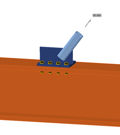
Obr. 2 Trojrozměrný pohled na zkoumaný přípoj.
Výpočty byly provedeny pro pět tlouštěk pásnice T-stub v rozmezí od 0,5 in. do 1,5 in. Maximální návrhové tahové zatížení, které lze na přípoj aplikovat, je uvedeno na obr. 3. U tradičních výpočtů se maximální zatížení s tloušťkou pásnice T-stub nemění, s výjimkou nejtenčí tloušťky pásnice T-stub, kde je pozorováno mírné snížení maximálního zatížení. Prokluz je rozhodujícím mezním stavem pro všechny tloušťky pásnice T-stub kromě nejtenčí, která je rozhodována tahovou únosností šroubů a ohybovým plastickým přetvořením T-stub. U výsledků CBFEM se maximální zatížení s tloušťkou pásnice T-stub mění průběžně.
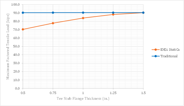
Obr. 3 Návrhová únosnost v závislosti na tloušťce pásnice T-stub pro přípoje kritické na prokluz
Důvod nesouladu lze identifikovat prostřednictvím podrobných výsledků poskytnutých IDEA StatiCa. Pro tento přípoj kritický na prokluz, který je namáhán tahem a smykem, platí ustanovení článku J3.9 AISC Specification (2016). Konkrétně je na odolnost proti prokluzu aplikován redukční součinitel ksc, který závisí na požadované tahové síle. IDEA StatiCa zahrnuje páčící sílu do požadované tahové síly použité pro výpočet ksc. Toto je konzervativní přístup, neboť to AISC Specification (2016) nevyžaduje a páčící síly nesnižují svěrnou sílu, která zajišťuje odolnost proti prokluzu. Pro nejtenčí zkoumanou pásnici vychází výsledek IDEA StatiCa o 23 % nižší únosnost než tradiční výpočty. Pro nejsilnější zkoumanou pásnici, kde je páčení zabráněno, dávají IDEA StatiCa a tradiční výpočty stejnou únosnost.
Páčení
Páčení ovlivňuje posouzení ohybové únosnosti plechu a únosnosti šroubů. Část 9 AISC Manual (2017) uvádí rovnice zohledňující páčení. Rovnice jsou uvedeny v několika formách pro různé návrhové situace. V této práci je ohybová únosnost plechu posuzována porovnáním tloušťky prvku (tj. pásnice T-stub nebo pásnice nosníku) s tmin dle rovnice 9-19 AISC Manual a únosnost šroubů je posuzována porovnáním požadované únosnosti šroubu (tj. Psinθ děleno počtem šroubů) s dostupnou tahovou únosností včetně vlivů páčení Tc dle rovnice 9-27 AISC Manual. S ohledem na použití metody LRFD pro tyto analýzy se tmin vypočítá jako:
\[t_{min} = \sqrt{\frac{4T_ub'}{\phi p F_u (1+\delta \alpha ') }}\]
\[b'= b-\frac{d_b}{2}\]
\[\delta = 1 - \frac{d'}{p}\]
\[\beta = \frac{1}{\rho} \left ( \frac{B_c}{T_u}-1 \right ) \]
\[\rho = \frac{b'}{a'}\]
\[a' = \left ( a + \frac{d_b}{2} \right ) \le \left ( 1.25 b + \frac{d_b}{2} \right ) \]
Pokud β ≥ 1
\[ \alpha ' = 1 \]
Pokud β < 1
\[ \alpha ' = \textrm{min} \left ( 1, \, \frac{1}{\delta} \frac{\beta}{1-\beta} \right ) \]
kde,
- Bc = dostupný tah na šroub na základě mezního stavu tahu nebo kombinovaných mezních stavů tahu a smykového porušení = ϕrn
- Fu = specifikovaná minimální mez pevnosti spojovacího prvku
- Tu = požadovaná tahová síla na šroub při použití kombinací zatížení LRFD = Psinθ/nb
- a = vzdálenost od osy šroubu k okraji prvku
- b = vzdálenost od osy šroubu k líci stojiny T-stub
- db = průměr šroubu
- d' = průměr otvoru
- p = přiřazená délka, na základě teorie čar plastických kloubů
- ϕ = 0,9 (pro ohyb plechu)
S ohledem na použití metody LRFD pro tyto analýzy se Tc vypočítá jako:
\[ T_c = B_c Q \]
Pokud \(\alpha ' < 0\) (což indikuje, že prvek má dostatečnou únosnost a tuhost).
\[Q=1\]
Pokud \(0 \le \alpha ' \le 1\) (což indikuje dostatečnou únosnost pro dosažení plné dostupné tahové únosnosti šroubu, avšak nedostatečnou pro zabránění páčení)
\[ Q = \left ( \frac{t}{t_c} \right )^2 (1+\delta \alpha ' ) \]
Pokud \( \alpha ' > 1\) (což indikuje nedostatečnou únosnost pro dosažení plné tahové únosnosti šroubu)
\[Q= \left ( \frac{t}{t_c} \right )^2 (1+\delta)\]
Poznámka: rovnice pro stanovení Q se liší od rovnice použité pro stanovení tmin.
\[ \alpha ' = \frac{1}{\delta (1+ \rho)} \left [ \left ( \frac{t_c}{t} \right )^2-1 \right ] \]
\[t_c = \sqrt{\frac{4B_c b'}{\phi p F_u}}\]
kde,
- t = tloušťka prvku
Páčení T-stub
Druhé šetření zkoumá únosnost T-stub a šroubů. Stejně jako v předchozím šetření jsou šrouby skupiny A (např. A325) se závity nevyloučenými ze střihových rovin; nosník je W18×175; tloušťka stojiny T-stub byla tw = 0,75 in.; šířka pásnice T-stub byla bf = 8,0 in.; tloušťka pásnice T-stub se měnila; a θ = 53,1°. Na rozdíl od předchozího šetření přípoje nebyly kritické na prokluz.
Výpočty byly provedeny pro osm tlouštěk pásnice T-stub v rozmezí od 0,25 in. do 1,25 in. Maximální návrhové tahové zatížení, které lze na přípoj aplikovat, je uvedeno na obr. 4. Jak se očekávalo, jak u výsledků tradičních výpočtů, tak u výsledků IDEA StatiCa se maximální návrhové tahové zatížení zvyšuje s tloušťkou pásnice T-stub, dokud není dosaženo plató, kde je páčení zabráněno. Na plató je únosnost přípoje řízena ustanoveními článku J3.7 AISC Specification (2016) a výsledky tradičních výpočtů a IDEA StatiCa se shodují. Tam, kde páčení ovlivňuje únosnost přípoje, existují rozdíly mezi tradičními výpočty, které se řídí pokyny části 9 AISC Manual (2017), a IDEA StatiCa, která explicitně modeluje přípoj pomocí CBFEM.
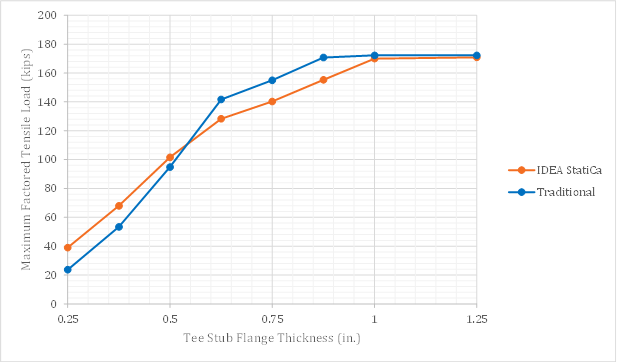
Obr. 4 Návrhová únosnost v závislosti na tloušťce pásnice T-stub pro přípoje s dorazem
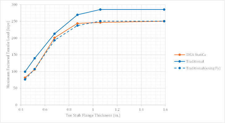
Obvykle se dostupná ohybová únosnost vypočítává na základě meze kluzu Fy. Rovnice pro páčení uvedené v části 9 AISC Manual (2017) jsou založeny na mezi pevnosti Fu, přičemž použití Fu místo Fy poskytuje lepší korelaci s dostupnými experimentálními daty. Obr. 5 uvádí stejná data jako obr. 4, avšak s přidáním tradičních výpočtů používajících Fy místo Fu. Pro tloušťky pásnice T-stub 3/4 in. a 7/8 in. přibližuje použití Fy v tradičním výpočtu výsledky k hodnotám IDEA StatiCa (kde je únosnost rovněž založena na Fy). Pro větší tloušťky je rozhodující únosnost šroubů, takže volba Fy nebo Fu výsledky neovlivňuje. Pro menší tloušťky použití Fy v tradičních výpočtech nesoulad zvyšuje.
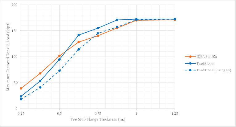
Obr. 5 Návrhová únosnost v závislosti na tloušťce pásnice T-stub pro přípoje s dorazem – včetně porovnání s tradičními výpočty používajícími Fy
Nesoulad mezi výsledky tradičních výpočtů a IDEA StatiCa pro páčení tenčích plechů byl dříve pozorován a zkoumán. Wald et al. (2020) porovnávali tradiční výpočty s výsledky metody konečných prvků založené na komponentách a s výsledky výzkumného modelu konečných prvků. Výsledky ukázaly, že ačkoli metoda konečných prvků založená na komponentách skutečně vykazuje vyšší únosnost než tradiční výpočty pro tenčí plechy, ve srovnání s výzkumným modelem zůstává zachována významná bezpečnostní rezerva. Studie Walda et al. (2020) byla v této práci rozšířena o porovnání s únosností vypočítanou pomocí rovnic pro páčení uvedených v části 9 AISC Manual (2017). Výsledky, které jsou superponovány na stávající výsledky z obr. 5.1.5 z Wald et al. (2020), jsou uvedeny na obr. 6. Pro tenčí plechy jsou výsledky AISC blízké výsledkům komponentové metody (CM).
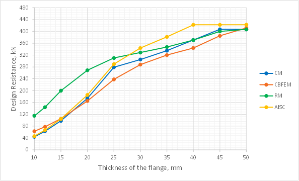
Obr. 6 Parametrická studie tloušťky pásnice – upraveno z obr. 5.1.5 Wald et al. (2020)
Velikost konečných prvků použitých v IDEA StatiCa může ovlivnit výsledky. Pro zkoumání citlivosti sítě byly analýzy opakovány se čtyřmi specifickými maximálními velikostmi prvků: 2 in., 1 in., 0,5 in., 0,3 in. a porovnány s předchozími výsledky při použití „výchozího" nastavení maximální velikosti prvku. Minimální velikost prvku byla rovna 0,3 in. pro všechny analýzy s výjimkou těch s maximální velikostí prvku 0,3 in., kde byla minimální velikost prvku nastavena na 0,2 in. Výsledky jsou vyneseny na obr. 7. Výsledky pro maximální velikosti prvků 2 in. a 1 in. byly shodné s výsledky pro výchozí maximální velikost prvku a jsou z grafu vyloučeny.
Menší maximální velikosti prvků snižují maximální zatížení, které lze na přípoj aplikovat dle IDEA StatiCa. Největší rozdíly jsou patrné pro tenčí plech. V důsledku toho výsledky IDEA StatiCa s maximální velikostí prvku 0,3 in. dobře odpovídají výsledkům tradičních výpočtů pro nejtenčí zkoumané plechy.
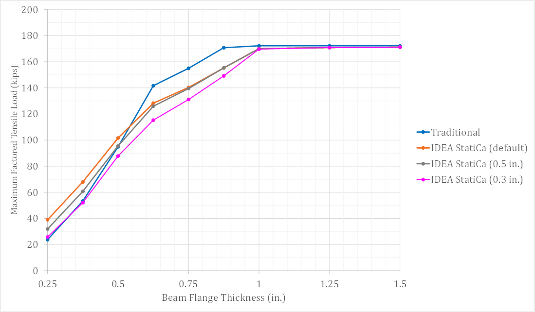
Obr. 7 Návrhová únosnost v závislosti na tloušťce pásnice T-stub pro přípoje s dorazem – včetně studie citlivosti sítě
Páčení pásnice nosníku
Třetí šetření zkoumá únosnost pásnice nosníku a šroubů. Pásnice nosníku byla měněna výběrem různých průřezů nosníků. Pro šetření bylo vybráno šest průřezů nosníků uvedených v tab. 1. Pro zvládnutí větších zatížení v tomto šetření jsou šrouby skupiny B (např. A490) se závity nevyloučenými ze střihových rovin; šířka pásnice T-stub byla bf = 8,0 in.; tloušťka pásnice T-stub byla tf = 1,25 in.; tloušťka stojiny T-stub byla tw = 0,75 in. a θ = 90°. Přípoje nebyly kritické na prokluz. V IDEA StatiCa bylo použito výchozí nastavení sítě.
Tab. 1 Vybrané parametry
| Průřez nosníku | tf (in.) | bf (in.) |
| W18×175 | 1,59 | 11,4 |
| W18×119 | 1,06 | 11,3 |
| W18×97 | 0,870 | 11,1 |
| W18×76 | 0,680 | 11,0 |
| W12×40 | 0,515 | 8,01 |
| W10×33 | 0,435 | 7,96 |
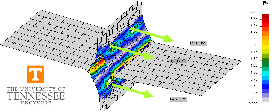
Maximální návrhové tahové zatížení, které lze na přípoj aplikovat, je uvedeno na obr. 9. Jak se očekávalo, jak u výsledků tradičních výpočtů, tak u výsledků IDEA StatiCa se maximální návrhové tahové zatížení zvyšuje s tloušťkou pásnice nosníku, dokud není dosaženo plató, kde je rozhodující ohyb T-stub. Páčení ovlivňuje únosnost každého z přípojů v tomto šetření. Pro tradiční výpočty byl přijat postup z části 9 AISC Manual (2017) spolu s předpokládaným vzorem čar plastických kloubů zobrazeným na obr. 8 (Dowswell 2011). IDEA StatiCa explicitně modeluje přípoj pomocí CBFEM. Vzor plastického přetvoření pozorovaný z výsledků CBFEM (obr. 10) souhlasil s předpokládanou čarou plastického kloubu použitou v tradičních výpočtech. IDEA StatiCa poskytla konzervativní výsledky ve srovnání s tradičními výpočty v celém zkoumaném rozsahu. Stejně jako dříve byly výsledky IDEA StatiCa porovnány také s variantou tradičních výpočtů, kde bylo použito Fy místo Fu. Použití Fy snížilo únosnost dle tradičních výpočtů tak, že se těsně shodovala s výsledky IDEA StatiCa.
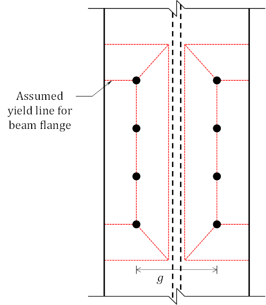
Obr. 8 Předpokládaný vzor čar plastických kloubů pro pásnici nosníku
Obr. 9 Návrhová únosnost v závislosti na tloušťce pásnice nosníku
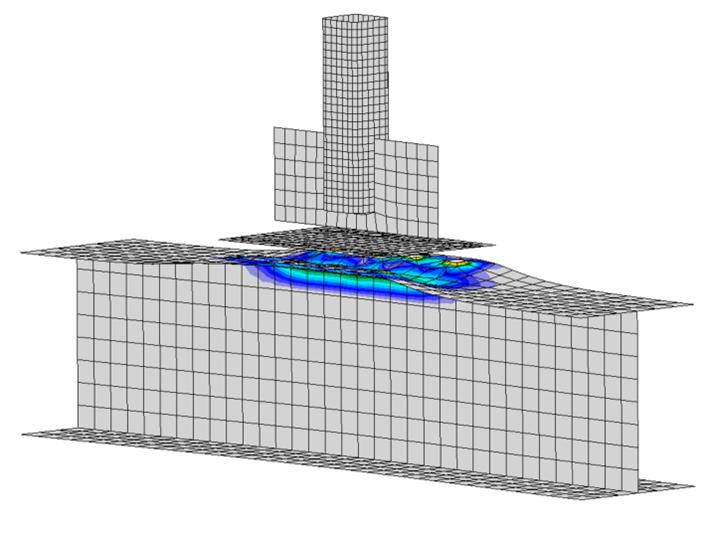
Obr. 10 Plastické přetvoření pro přípoj s nosníkem W10×33 (měřítko deformace = 5)
Shrnutí
Tato studie porovnávala návrh T-stub přípojů tradičními výpočetními metodami používanými v praxi v USA a IDEA StatiCa. Klíčová zjištění studie zahrnují:
- Dostupná únosnost získaná z IDEA StatiCa dobře odpovídá tradičním výpočtům, přičemž rozdíly jsou převážně na konzervativní straně.
- Při posuzování přípojů kritických na prokluz namáhaných kombinací tahu a smyku IDEA StatiCa konzervativně zohledňuje pouze tah ve šroubech, nikoli kontaktní tlak na styčných plochách (tj. páčící sílu) při stanovení dostupné únosnosti.
- Část rozdílů v únosnosti přípoje je způsobena tím, že rovnice pro páčení uvedené v části 9 AISC Manual jsou založeny na mezi pevnosti Fu, zatímco IDEA StatiCa omezuje napětí na mez kluzu Fy.
- IDEA StatiCa vykazovala vyšší únosnost než tradiční výpočty pro případy zkoumaných tenčích pásnic. Nicméně pro tyto případy zůstává zachována významná bezpečnostní rezerva ve srovnání s výsledky podrobného modelu konečných prvků.
- Byla pozorována určitá závislost na velikosti sítě. Pro případy, kde byl rozhodující limit plastického přetvoření, IDEA StatiCa vykazovala sníženou únosnost při nastavení velikosti sítě menší než výchozí.
Literatura
AISC. (2016). Specification for Structural Steel Buildings. American Institute of Steel Construction, Chicago, Illinois.
AISC. (2017). Steel Construction Manual, 15th Edition. American Institute of Steel Construction, Chicago, Illinois.
AISC. (2019). Steel Construction Manual Design Examples, v15.1. American Institute of Steel Construction, Chicago, Illinois.
Dowswell, B. (2011). "A Yield Line Component Method for Bolted Flange Connections." Engineering Journal, AISC, (2nd Quarter), 93–116.