Structural design of a reinforced concrete slab (EN)
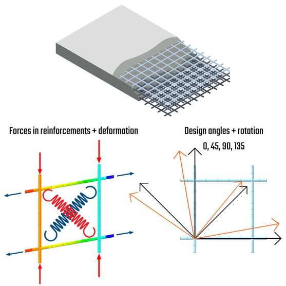
The main goal of our job is to determine the internal forces within the structure's shells. The internal forces on slabs and walls are transformed according to Baumann's method into design internal forces, which depend on the angle specified by the user. These internal forces are then used as the input for the ULS and SLS assessments.
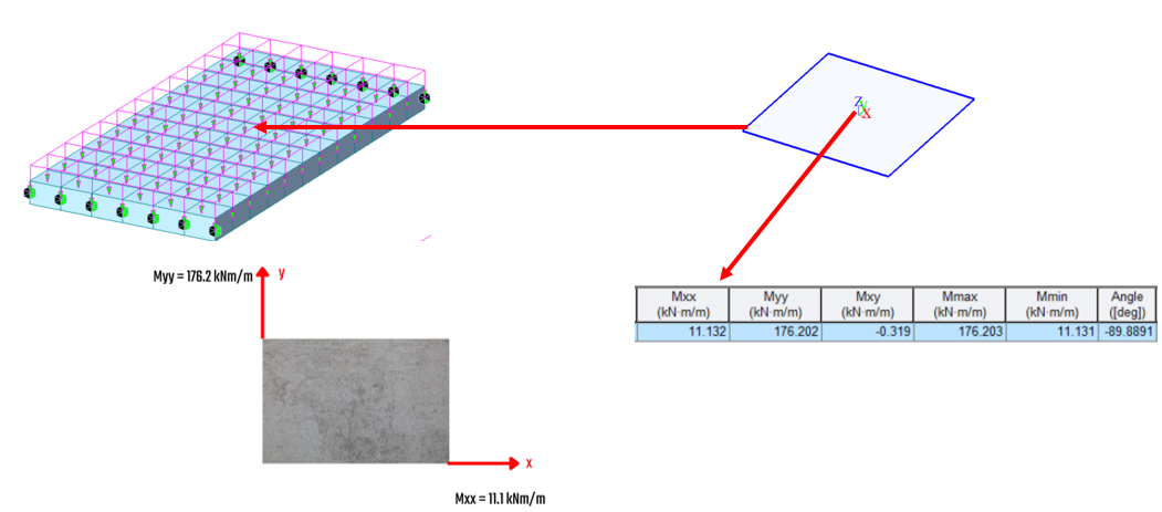
Global model and internal forces
The deck will be checked at the middle span of the simply supported orthogonal bridge deck under a uniform load. The moments in the local direction of the slab are outlined and will be used for the upcoming calculation procedure.
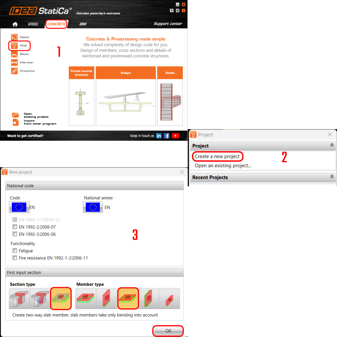
New project
Let’s launch IDEA StatiCa, go to the Concrete tab, and select the application RCS. Create a new project by clicking Create a new project. In the next dialog, stay with the default general Eurocode settings and select a 2D section and Slab member type.
Cross-section
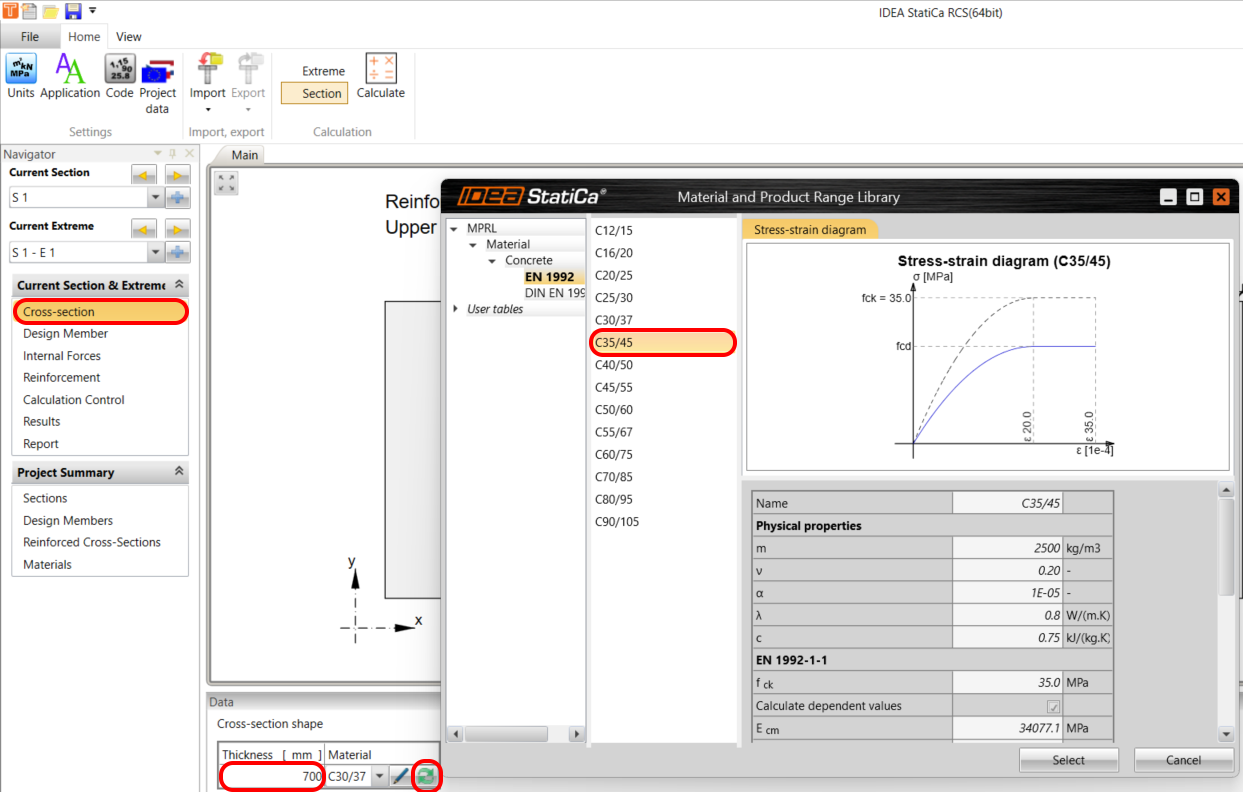
The design requires the use of a 1 x 1 m slab element with a thickness of 700 mm and a concrete grade of C35/45. This is the simple input of geometry and material properties.
Design member
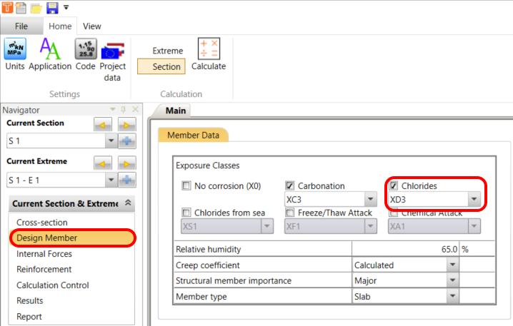
The section's exposure class determines its maximum crack width and detailing evaluation. Change the Chlorides class to XD3.
Internal forces
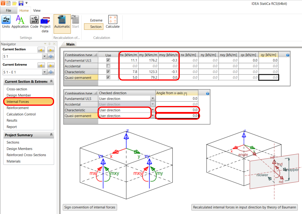
The combinations for ULS and SLS should be input for the current extreme. Based on the information, the fact that you work with only one combination makes it much simpler. Insert the internal forces Fundamentals ULS, Characteristic and Quasi-permanent combinations. Switch the direction check for Characteristic and Quasi combination to User-defined and set the angle to 0 (see the important notice at the end of the tutorial).
Checked direction
Read the theoretical background about the Checked direction. The direction of the check has to be determined for a proper check of the 2D element. The direction of the check can be entered for each combination type separately using the following method:
- User-defined direction – the user defines the check direction as an angle relative to the x-axis in the plane of the 2D element. This option is set as default for the ULS combination type and the predefined value of the angle is 0 degrees.
Reinforcement
The template will assist you in quickly designing orthogonal reinforcement with links.
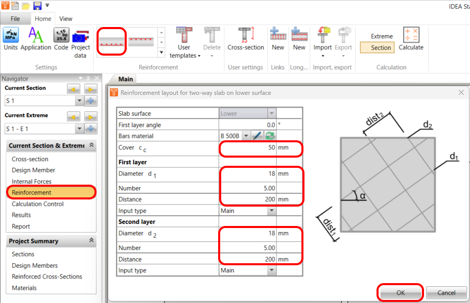
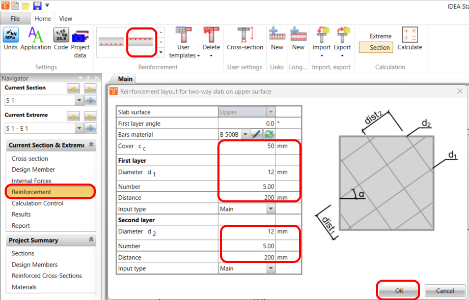
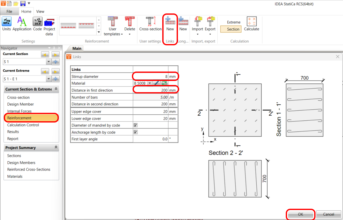
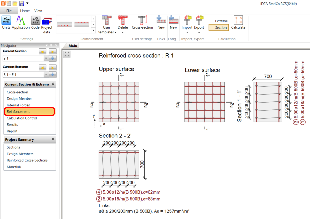
The final reinforcement scheme should look like this:
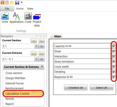
Calculation control
To ensure that all necessary checks are carried out, please select all the required checks.
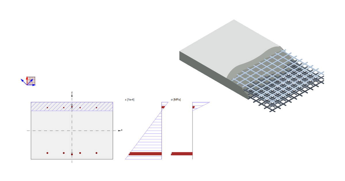
Results
The Baumann method involves evaluating the results of a section at four different angles – 0, 45, 90, and 135 degrees. This analysis provides a comprehensive understanding of how the section behaves under different angles. You can learn more about this method in the webinar titled "Baumann's Method for Design of Concrete Shells in Practice", where additional theory is explained.
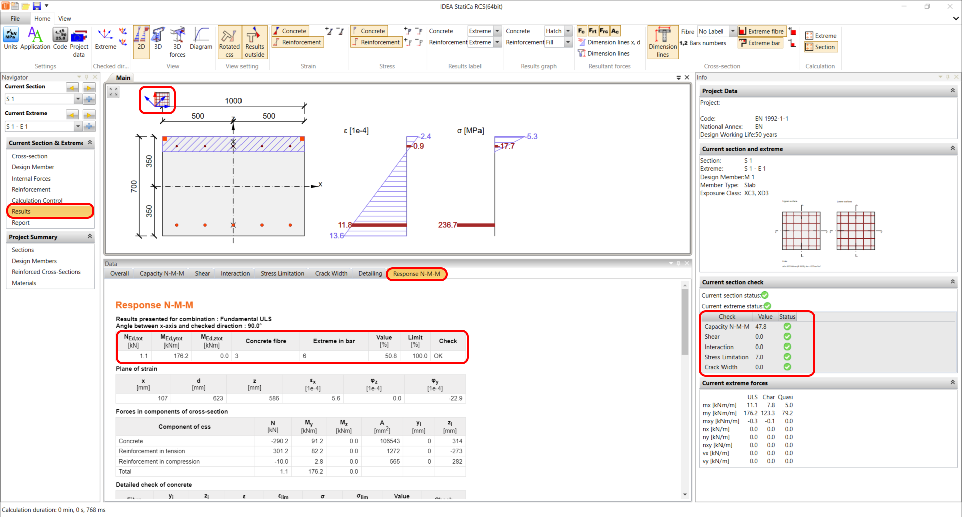
Results for ULS with maximal utilization in the Response check of 50.8 %:
Report
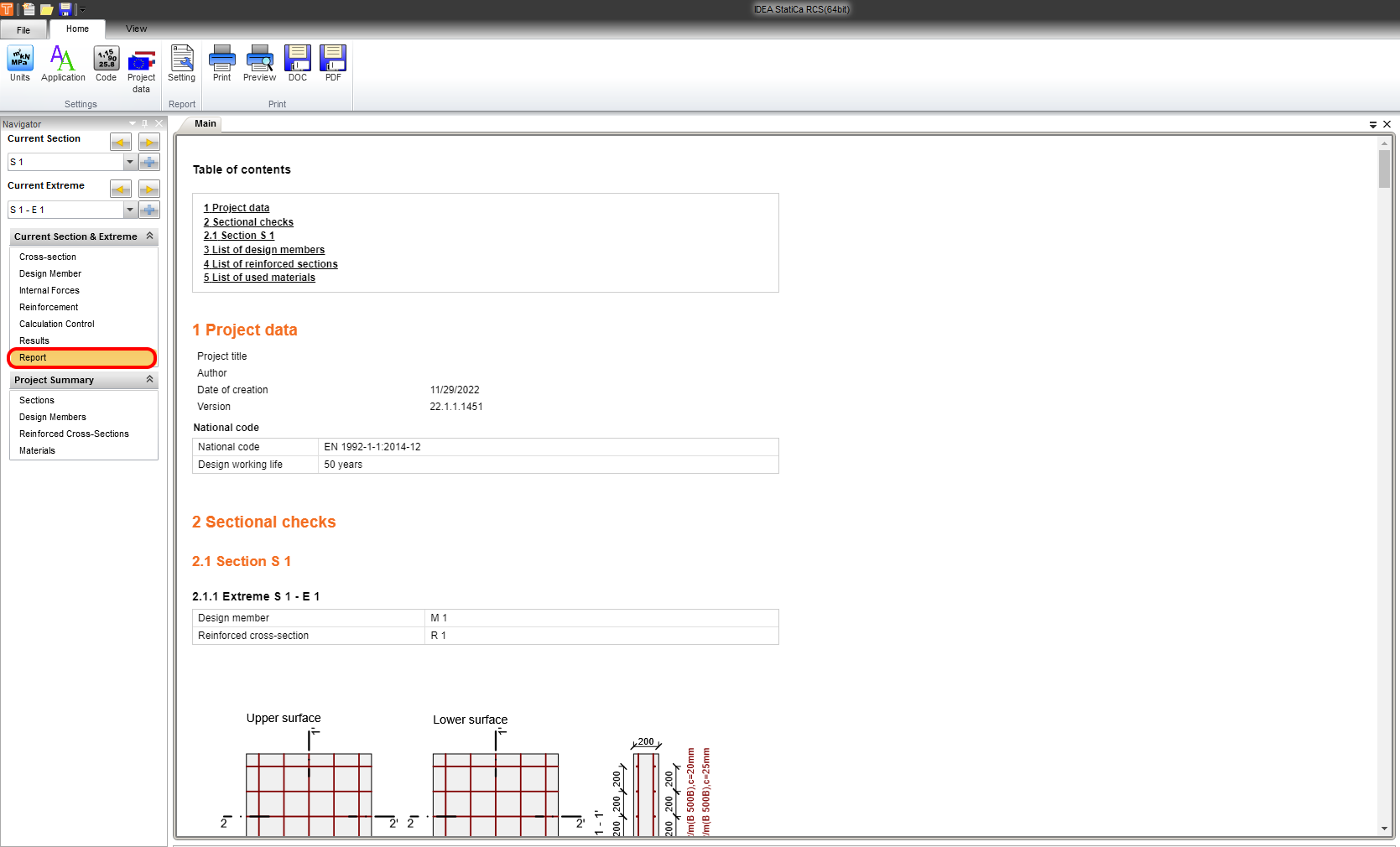
Finally, go to Report Preview/Print. IDEA StatiCa offers a fully customizable report to print out or save in an editable format.
Important notice!
The default value for the User-defined angle is set as zero. Please read the recommendation from our Theoretical Background:
- If the reinforcement bars are perpendicular to each other, check the results are similar for different checked direction angles, they are not dependent on the defined reinforcement angle and the maximum value of the check is found for angles 0, 45, and 90 degrees. Therefore, this check can be performed for the predefined direction of a check angle of 0 degrees.
- If the reinforcement bars are not perpendicular to each other, the results of the checks differ significantly and the maximum check value is achieved approximately in the direction corresponding with the direction of average reinforcement. Therefore, it is recommended to change the predefined check direction or to perform checks in more directions in cases when reinforcement bars are not perpendicular to each other.
Internal forces
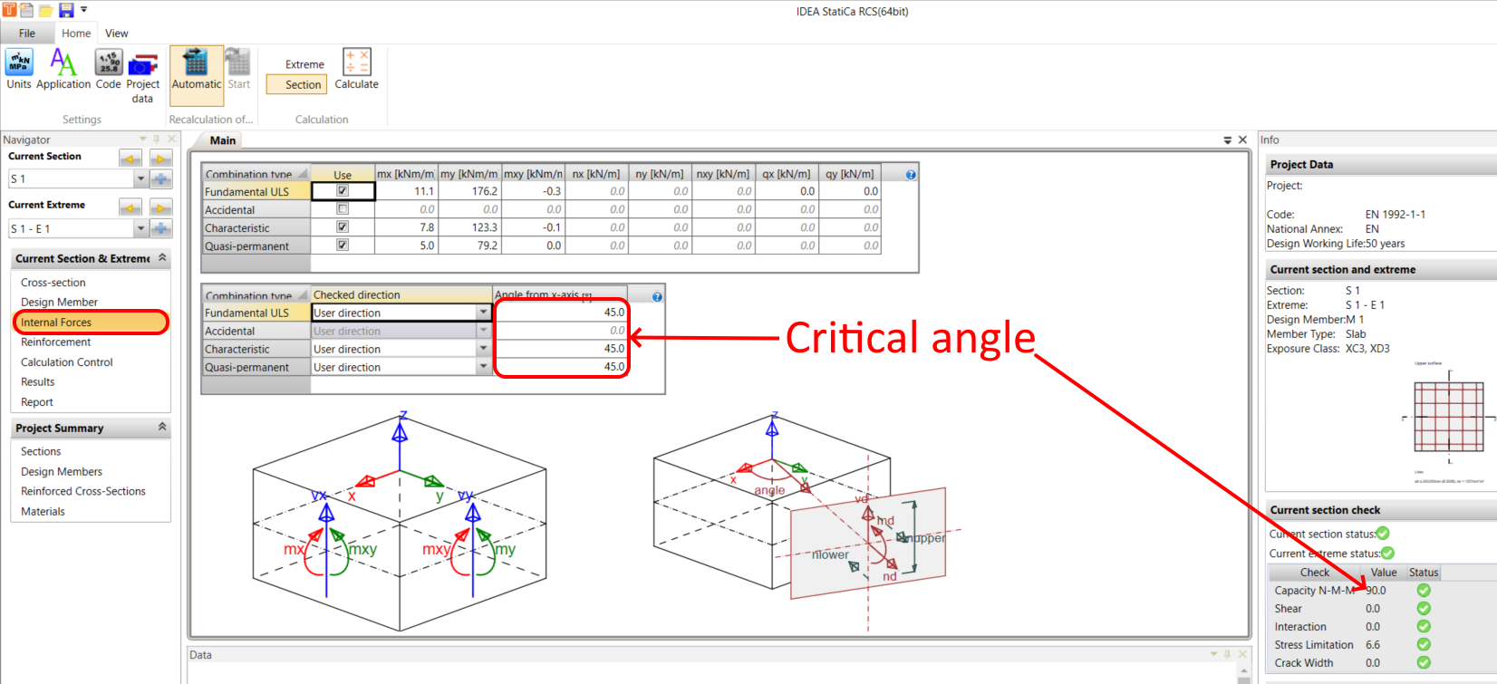
The critical angle is 45 degrees and has to be set by the user.
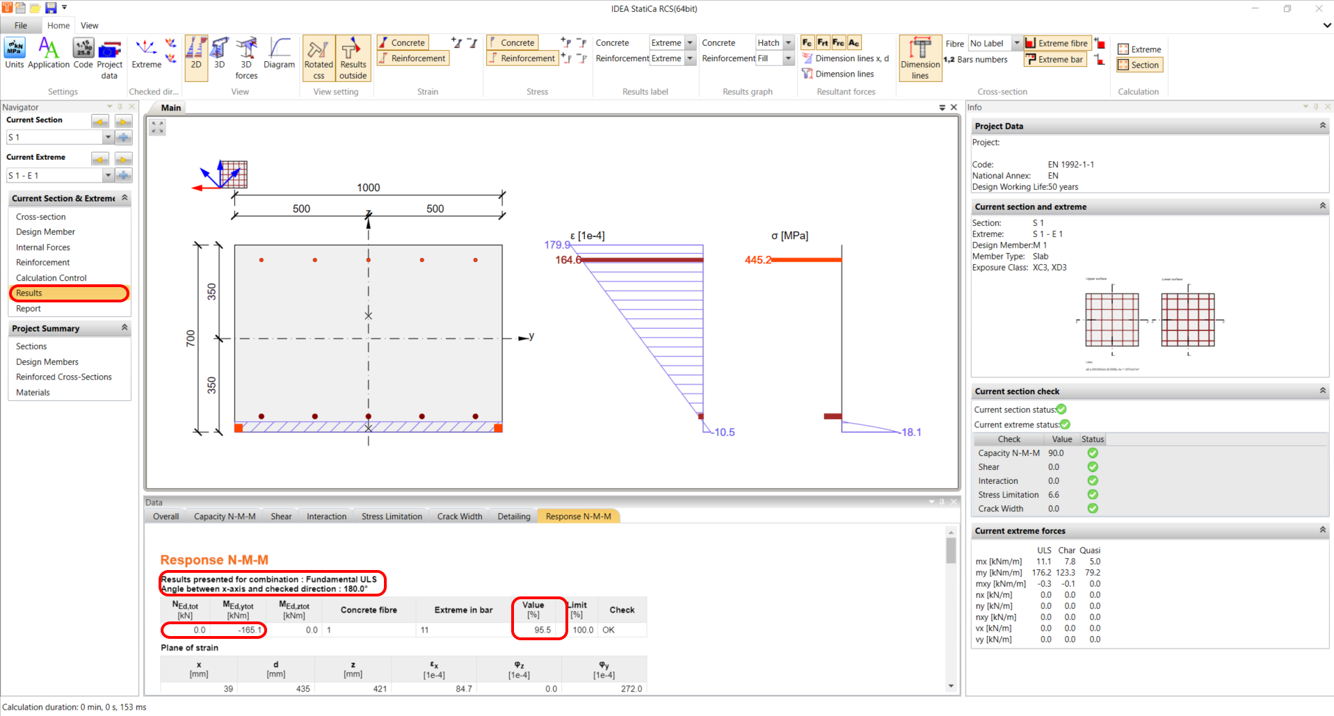
Results
From the angle alteration, it is evident that the utilization for the Response check has increased from 50.8% to 95.5%.