
Modeling options – Negative volume, Cutting plane and Cut, Related to Center Point
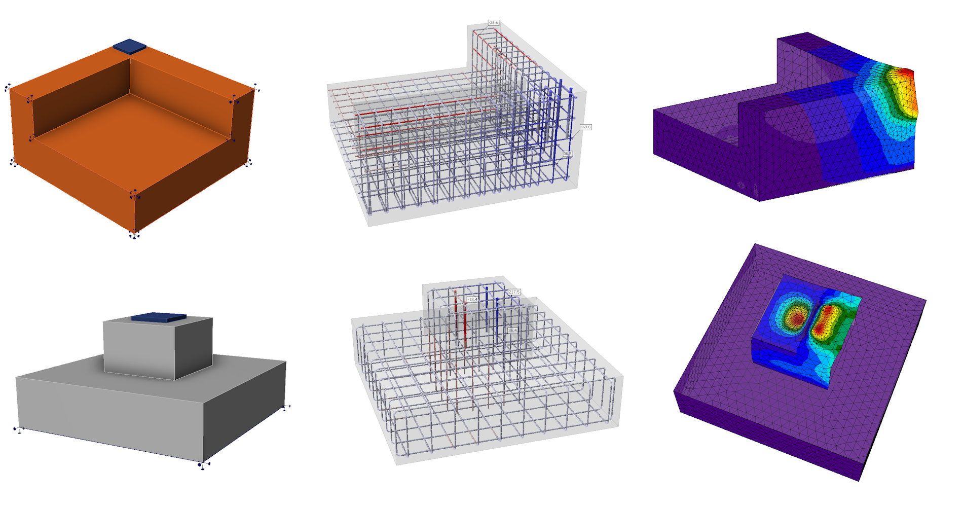
Complex shapes of anchoring
Additional modeling operations enable the creation of more complex shapes and expand potential applications, including pedestals, non-rectangular anchor blocks, foundation strip extensions, and anchoring near openings. We are, therefore, moving towards a more general use of the application. However, it is important to note that the application is only suitable for the anchoring cases for which it is verified.
Further development and verifications are needed to assess punching and other more complex and general cases. These cases are not supported in versions 25.0 and 25.1.
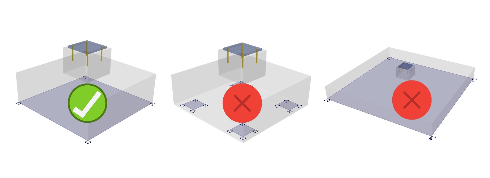
Note: In the case of surface support, failure always occurs at the anchorage area, and punching does not play a role. Only in cases of soils with low stiffness may punching occur, or also in the case of pile caps. For these situations, the software is not yet suitable for such use.
The Cut operation
The basic operation for adjusting the block shape is the Cut operation. The Cut can be according to a negative volume or a cutting plane, these can be found under the "model entity" button.
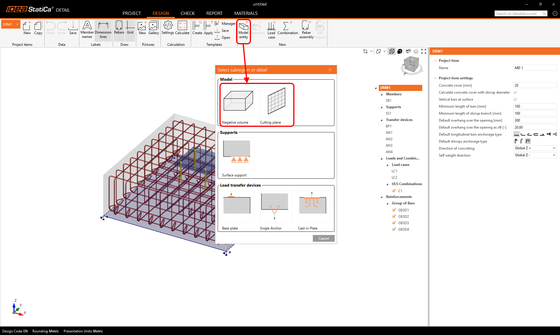
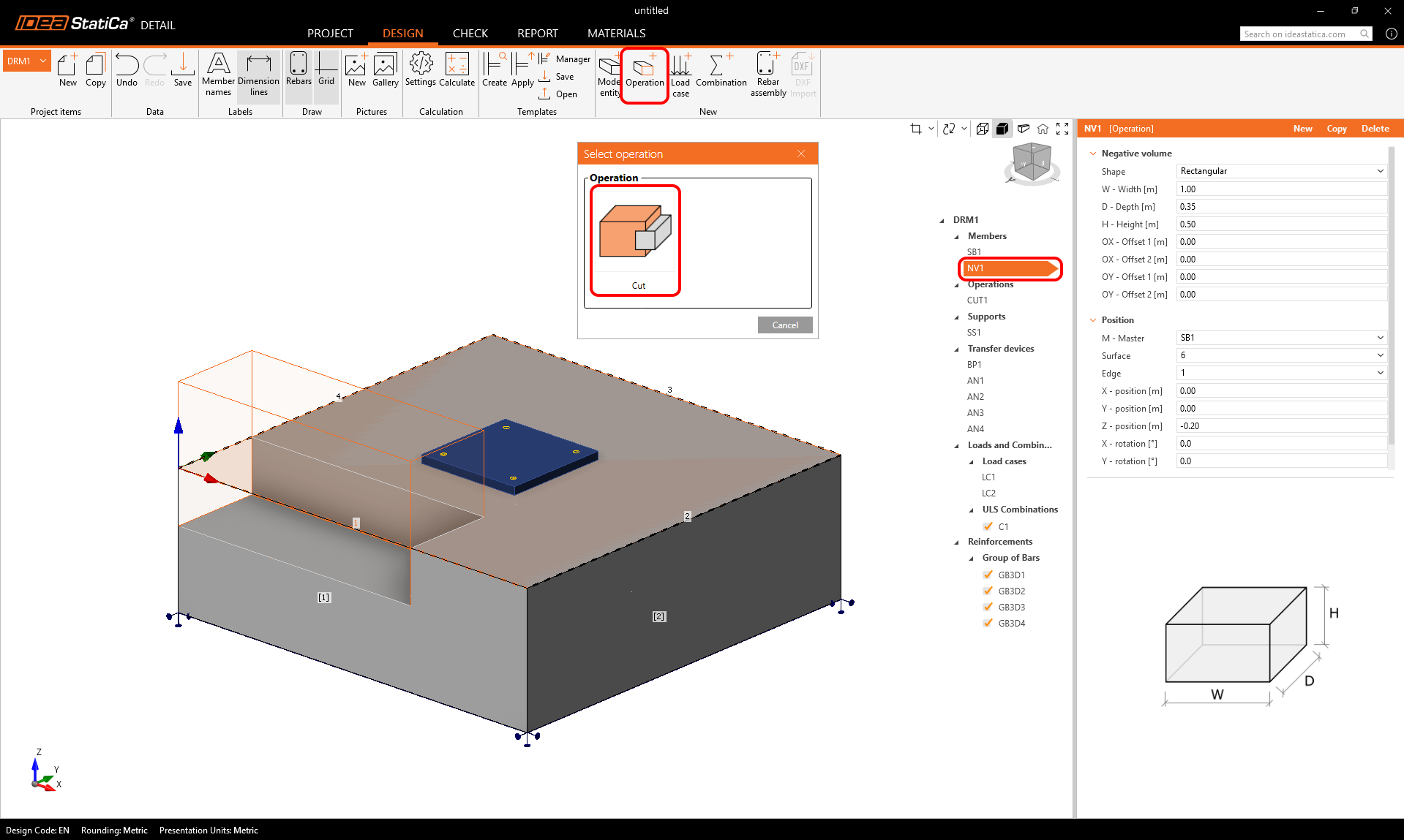
- The Cut operation is applied to the negative volume or cutting plane to adapt the host block using the operation.
- A Cutting plane works in a similar way. As shown in the following figure, any cut generates new edges and surfaces that can serve as references for placing reinforcement.
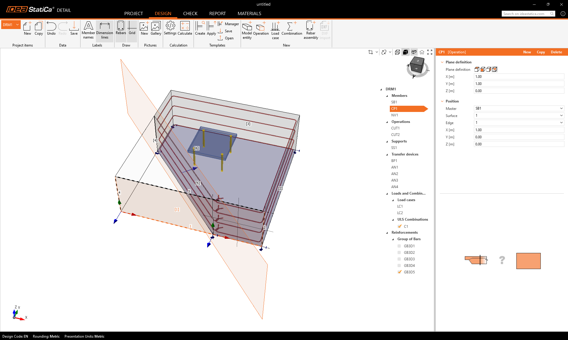
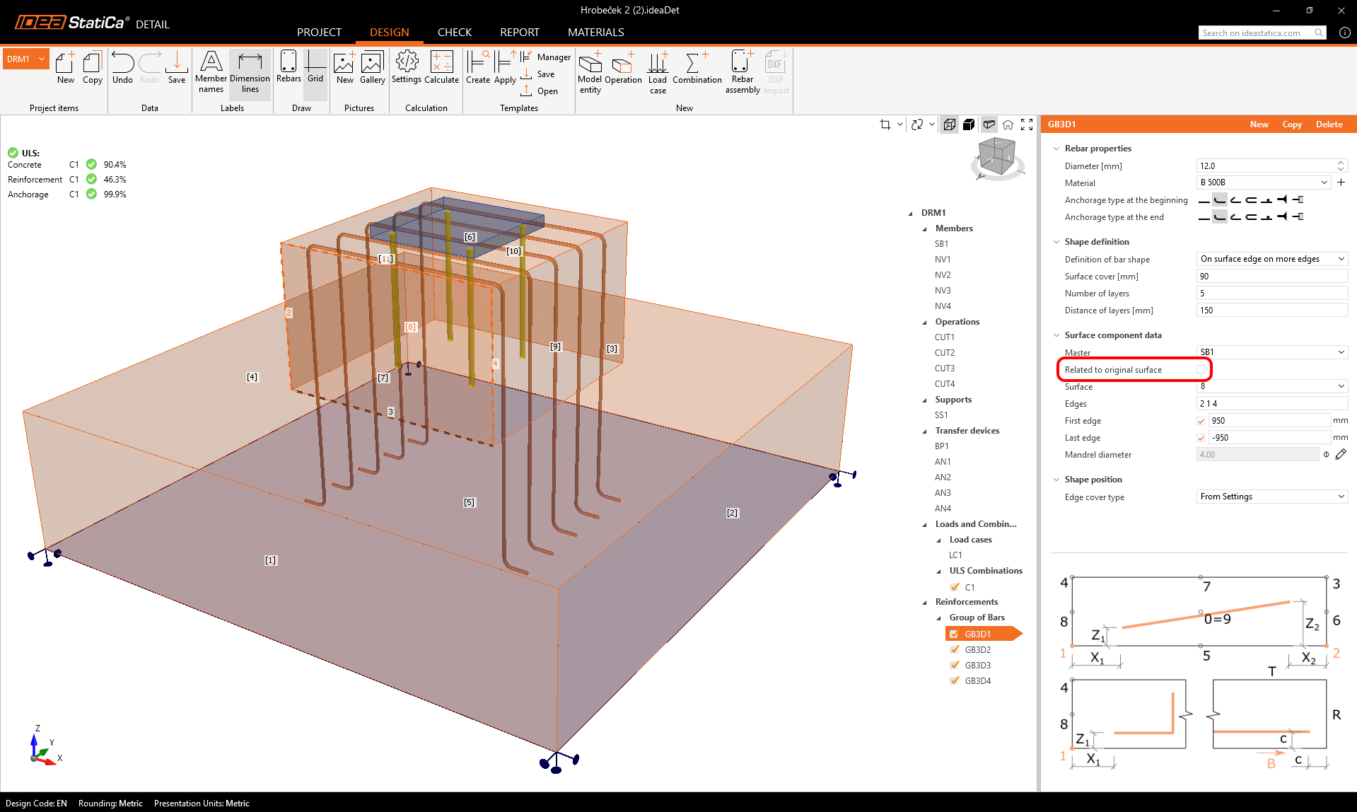
- After the first Cut operation is applied, reinforcement can be referenced to either the original or newly created faces and edges. This is controlled through a new setting in the property grid.
Released in IDEA StatiCa version 25.0.
Anchors tied to the base plate and referenced to the center
With the referencing system in Detail 3D, users can position model entities - such as base plates, anchors, supports, and loads - relative to the center point of their master entity instead of only from an edge. This means anchors can be placed directly in relation to the base plate, and all connected components automatically adjust when the geometry changes. The “Related to: Edge / Center point” option in the Property Grid makes modeling faster, more intuitive, and ensures consistent alignment without manual repositioning.
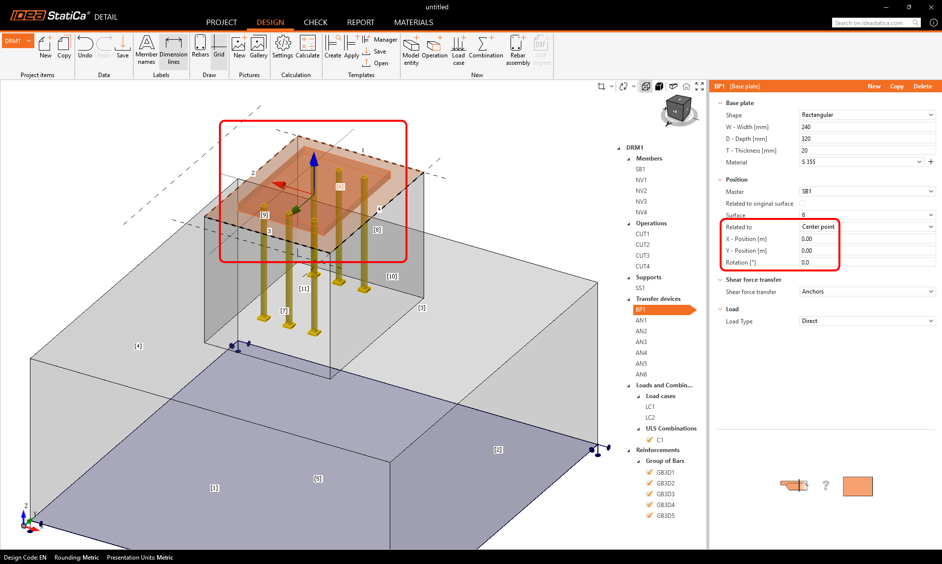
The following entities support reference to the center:
- Base plate (Related to the Center of the solid block surface)
- Support defined by polyline (Related to the Center of the solid block surface)
- Point load (only for Cast-in plate)
- Surface load defined by polyline (Related to the Center of the solid block surface)
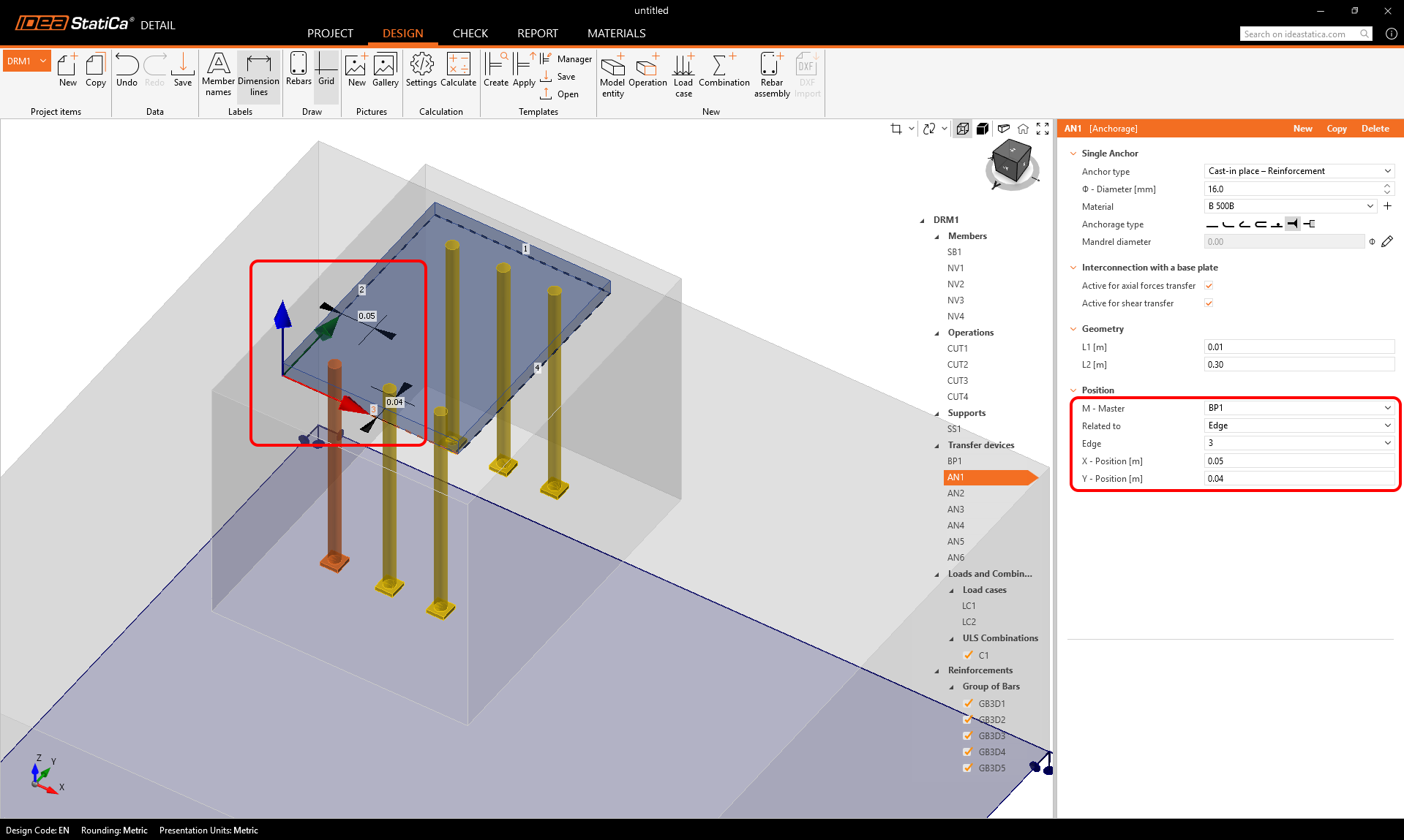
- Single anchor (Related to the Center of the solid block surface or Base plate)
Released in IDEA StatiCa version 25.1.