Long Bolted and Welded Connections (AISC)
Mark D. Denavit and Rick Mulholland prepared this verification example in a joint project of The University of Tennessee and IDEA StatiCa.
Description
A comparison between results from the component-based finite element method (CBFEM) and traditional calculation methods used in US practice for long end-loaded bolted and welded connections is presented in this study. The focus of this study is on the limit states of bolt shear for long bolted connections, and weld rupture for long welded connections. Special consideration is given to the effect of differential strain that produces a non-uniform distribution of load between fasteners and non-uniform stress in long fillet welds. Comparisons to experimental results are also presented.
Traditional calculations are performed in accordance with the provisions for load and resistance factor design (LRFD) in the AISC Specification (AISC 2022). The CBFEM results were obtained from IDEA StatiCa version 23.0. The maximum permitted loads were determined iteratively by adjusting the applied load input to a value that the program deems safe, but if increased by a small amount (0.1 kip), the program would deem unsafe by exceeding the 5% plastic strain limit or exceeding 100% bolt or weld utilization. DR type analyses can help identify maximum permitted loads. However, some approximation is made in the evaluation of the joint design resistance, therefore all results in this report are based on EPS type analysis.
Requirements for Long Bolted and Welded Connections in the AISC Specification
Experiments and analyses of long end-loaded bolted and welded connections have shown that stress in the bolts and welds is not uniform (Kulak et al. 2001, Miller 2003). The stress in the bolts and weld near the ends of the connection is greater than it is near the middle. The distribution of stress along the length depends on the stiffness of the bolts or welds relative to the stiffness of the connected materials. The AISC Specification captures this behavior with simple strength reductions.
Bolted Connections
The design strength, \(\phi R_n\), for the limit state bolt shear is defined in AISC Specification Section J3.7 as:
\[ \phi R_n = \phi F_{nv} A_{b} \]
where:
- \(\phi=0.75\)
- \(F_{nv}\) – nominal shear stress of the bolt
- \(A_b\) – nominal unthreaded body area of the bolt
AISC Specification Table J3.2 lists values for the nominal shear stress of fasteners and threaded parts, Fnv. Footnote [c] of the table states, “For end-loaded connections with a fastener pattern length greater than 38 in. (950 mm), Fnv shall be reduced to 83.3% of the tabulated values”, and defines fastener length as “the maximum distance parallel to the line of force between the centerline of the bolts connecting two parts with one faying surface.”
The nominal shear stress, Fnv, is a percentage of the ultimate tensile stress of the bolt, Fu, and is calculated according to the commentary on the AISC Specification as follows:
- When threads are excluded from the shear planes,
\[ F_{nv} = 0.563 F_u \]
- When threads are not excluded from the shear plane,
\[ F_{nv} = 0.45 F_u \]
The factor 0.563 is equal to 0.625, the shear/tension strength ratio, times 0.90, a length reduction factor. The factor of 0.45 is 80% of 0.563, and accounts for the reduced area of the threaded portion. The length reduction factor of 0.90 accounts for differential strain in connections up to 38 in., after which the additional 0.833 length reduction factor is imposed for a combined reduction factor of 0.90 × 0.833 = 0.75 for length effects. These reduction factors are based on a statistical analysis of test data from 79 bolted and riveted connections across 11 different experimental investigations (Tide, 2010).
Welded Connections
The design strength, \(\phi R_n\), for the limit state of weld rupture is defined in AISC Specification Section J2.4 as:
\[ \phi R_n = \phi F_{nw} A_{we} k_{ds} \]
where:
- \(\phi\) – resistance factor
- \(F_{nw}\) – nominal stress of the weld metal
- \(A_{we}\) – nominal effective area of the weld
- \(k_{ds}\) – directional strength increase factor
The directional strength increase factor, kds, is calculated as:
\[ k_{ds} = (1.0+0.5 \sin^{1.5} \theta ) \]
where \(\theta\) is the angle between the line of action of the required force and the weld longitudinal axis. For the connections investigated in this study, \(\theta = 0\) and thus \(k_{ds} = 1\) for the traditional calculations. In IDEA StatiCa, \(\theta\) is determined from the resultant forces in each weld segment and can vary from zero (for example because of the Poisson effect).
AISC Specification Table J2.5 provides values for \(\phi\) and Fnw for welds loaded in shear as 0.75 and 0.60FEXX, respectively, where FEXX is the filler metal classification strength.
The nominal effective area of the weld, Awe, is defined for fillet welds in AISC Specification Section J2.2a as the effective length multiplied by the effective throat, where the effective throat is the shortest distance from the root to the face of the weld, and the effective length is the length of the centerline of the weld along the center of the plane through the throat.
AISC Specification Section J2.2b(d) provides the following limitations on the effective length of end-loaded fillet welds:
- For fillet welds with a length up to 100 times the weld size, it is permitted to take the effective length equal to the actual length
- When the length of the fillet weld exceeds 100 times the weld size, the effective length shall be determined by multiplying the actual length by the reduction factor, β, determined as:
\[ \beta = 1.2-0.002 (l/w) \le 1.0 \]
where:
\( l \) – actual length of end-loaded weld
\(w\) – size of weld leg
- When the length of the weld exceeds 300 times the leg size, w, the effective length shall be taken as 180w.
According to the commentary on the AISC Specification (AISC 2022), the reduction factor β is a simplified approximation of exponential formulas based on many years of tests and finite element models and is equivalent to the reduction given in the Eurocode (CEN 2005).
Long Bolted Connections
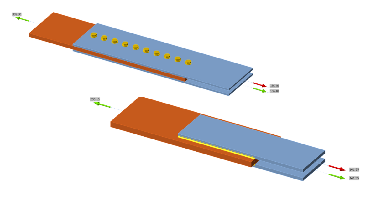
To investigate the effect of differential strain on the overall connection strength for long bolted connections, a simple tension splice connection is used. The connection consists of a test plate bolted between two reaction plates using a single line of 3/4 in. diameter A325 bolts in standard holes, with threads not excluded from the shear plane. To investigate the effect of plate stiffness on the force distribution to the individual bolts, test plate thicknesses of 1/2 in., 1 in., and 2 in., were analyzed. The thickness of each reaction plate was taken as half the thickness of the test plate. The width of all plates was 12 in. A three-dimensional view of the connection with test plate thickness equal to 1 in. and connection length equal to 27 in. is presented in Figure 1.
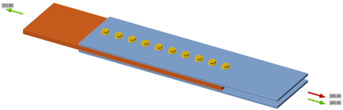
Figure 1 Three-dimensional view of tension splice connection (test plate thickness = 1 in., connection length = 27 in.)
The connection was designed to fail in bolt shear. To ensure the shear strength of the bolt controlled over tensile yielding and tensile rupture of the plate, a high strength material with Fy = 100 ksi was selected for the plates. Bearing and tearout at the bolt holes were checked but designed to not control by selection of materials and providing sufficient bolt spacing and edge distance. The edge distance in the direction of force was 2-1/2 in., and the bolt spacing was 3 in. for all connections.
Seventeen connections were tested, with length increasing in 3 in. increments between 3 in. and 51 in. Given that the bolt spacing was always 3 in., the connection length corresponds to the number of bolts used (e.g., the 27 in. long connections have 10 bolts). A comparison of strength vs. connection length is presented in Figure 2, and the distributions of bolt shear force (in each shear plane) for connection lengths of 12 in., 24 in., 36 in., and 48 in. are presented in Figure 3
The strength according to the AISC Specification increases linearly up to a connection length of 36 in., beyond which a sharp drop in strength occurs due to the 0.833 length reduction factor. Past this point, the strength again continues to increase linearly. The IDEA StatiCa strengths align well with the AISC strengths for shorter connection lengths, but unlike the AISC strengths, the strength increase for longer connections in IDEA StatiCa is non-linear. The degree of non-linearity is dependent on the stiffness of the plate because the stiffness of the bolts and plate are realistically modeled in IDEA StatiCa capturing the non-uniform distribution of bolt forces.
The shear force distributions in Figure 3 shows the effect of differential strain on the force in the individual bolts as captured by the IDEA StatiCa analyses, and how this effect is impacted by plate stiffness. The force in the bolts at the ends of the connection is greatest and decreases as the distance from the ends of the connection to the location of the bolt increases. This effect is reduced for stiffer plates.
With explicit modeling of bolt and plate stiffness in IDEA StatiCa, the degree of strength reduction due to length effects is dependent on the size of the bolts in relation to the size of the plates in addition to the connection geometry. The actual strength reduction also depends on these parameters (Kulak et al. 2001). The simplified reductions in the AISC Specification depend only on connection length. IDEA StatiCa exhibits reductions greater than that specified by AISC Specification as shown with the connection with the 1/2 in. thick test plate, and reductions less than that specified by AISC Specification as shown with the connection with the 1 and 2 in. thick test plates for a range of connection lengths greater than 38 in. From these results it is clear that IDEA StatiCa captures the intent of the length effect reduction of Footnote [c] of AISC Specification Table J3.2. Note that the 0.9 reduction factor for length effects that is incorporated in Fnv is conservatively used in IDEA StatiCa. Thus, for connections less than 38 in. in length, length effects are essentially double counted in IDEA StatiCa, once with the 0.9 reduction factor and again by explicitly modeling the non-uniform force distribution in the bolt group. However, the 0.9 reduction factor may also account for other effects and should not be excluded without further research.

Figure 2 Comparison of strength vs connection length for a bolted tension splice connection
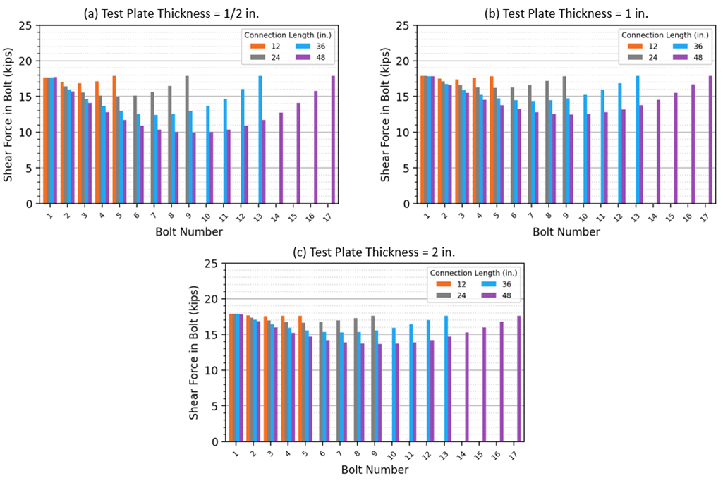
Figure 3 Bolt shear force distributions for connection lengths of 12 in., 24 in., 36 in., and 48 in., for test plate thicknesses of 1/2 in., 1 in., and 2 in.
Comparison to Experimental Results
To expand on the investigation of long bolted connections, this section includes comparisons to previously published experimental results. For these comparisons, measured material and geometric properties reported by the experimentalists were used in the calculations and analyses. The bolt shear strength reported by the experimentalists was found through shear testing of a single bolt taken from the same lot as was used in the test specimens. Therefore, for the traditional calculations, Fnv is taken equal to 0.9 times the reported bolt shear strength when the connection length is less than or equal to 38 in., and taken equal to 0.833 times this value (i.e., 0.75 times the reported bolt shear strength) when the connection length is greater than 38 in. For the IDEA StatiCa analyses, the model is defined such that the value of Fnv used in the bolt strength calculations is equal to 0.9 times the reported bolt shear strength.
For the traditional calculations, resistance factors were not applied. For the IDEA StatiCa analyses, the resistance factors for material, bolts, and welds were set to 1.0 in the code setup.
Bendigo et al. 1963
Bendigo et al. (1963) performed tensile tests of bolted splice connections. Sixteen plates of varying widths and thicknesses were loaded between two reaction plates in tension through two lines of 7/8 in. diameter A325 bolts in 15/16 in. diameter standard holes. Four specimens, D31, D41, D51, and D61, failed in tensile rupture of the plate, and the rest failed in bolt shear for at least one bolt. The typical connection configuration for the specimens in the study is presented in Figure 4(a), and a three-dimensional view of the IDEA StatiCa model for specimen D101 is presented in Figure 4(b). The geometric and material properties of the test specimens are presented in Table 1.
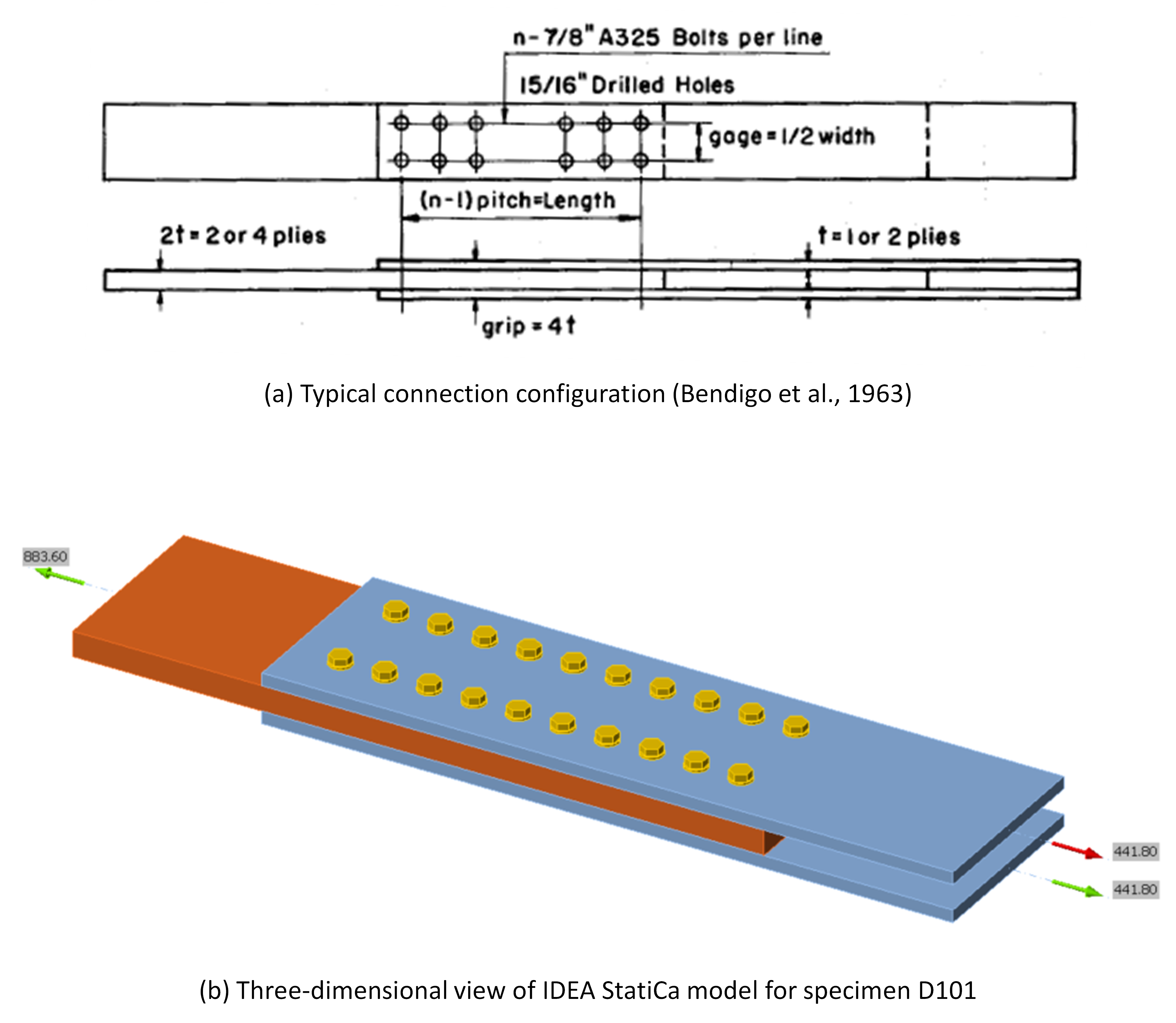
Figure 4 (a) Connection configuration for the Bendigo et al. experimental investigation (Bendigo et al., 1963); (b) three-dimensional view of IDEA StatiCa model for specimen D101
The sixteen specimens were modeled in IDEA StatiCa. The strength of each connection was also computed according to traditional calculations using the AISC Specification equations with measured material and geometric properties but without resistance factors. The results of the comparison between the experimental strength, Pexp, IDEA StatiCa strength, PIDEA, and the AISC Specification strength, PAISC, are presented in Table 2 and Figure 5.
The 5% plastic strain limit controlled the IDEA StatiCa strengths, and tensile yielding controlled the AISC strengths for all specimens. Both the IDEA StatiCa and AISC strengths are significantly lower than the experimental strengths. This is because for the experimental tests, the failure modes of tensile rupture and bolt shear occurred at loads well after yielding of the plate occurred. The experiments by Bendigo et al. (1963) were included in the analysis to develop the reduction factors for length effects that appear in the AISC Specification (Tide 2010). As seen in Figure 3, the difference in bolt force between end bolts and middle bolts increases with reductions in thickness (i.e., reductions in plate stiffness). Specimens that exhibit bolt failure well after yielding of the plate may show exaggerated length effects.
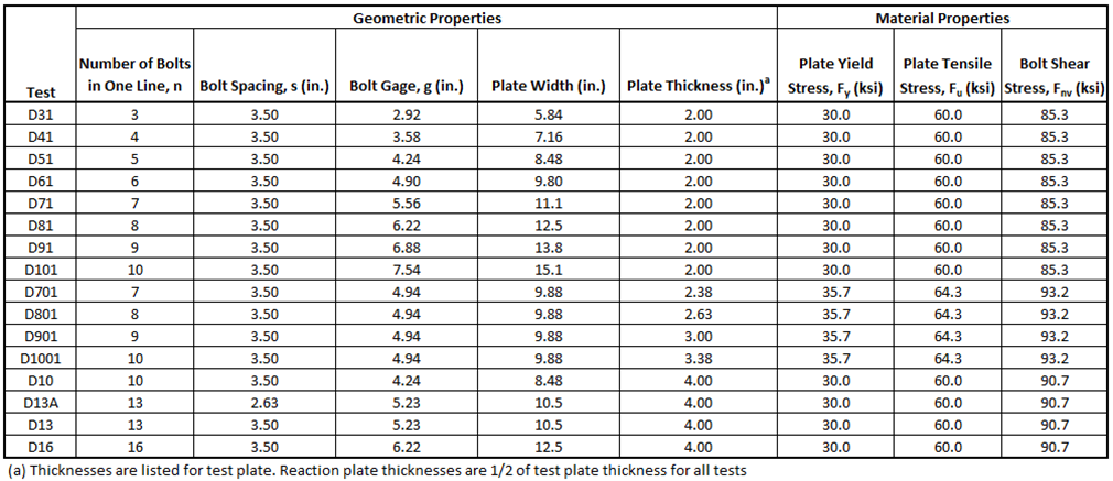
Table 1 Test specimen geometric and material properties for the Bendigo et al. (1963) experimental investigation
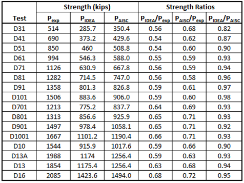
Table 2 Comparison to the Bendigo et al. (1963) experimental investigation
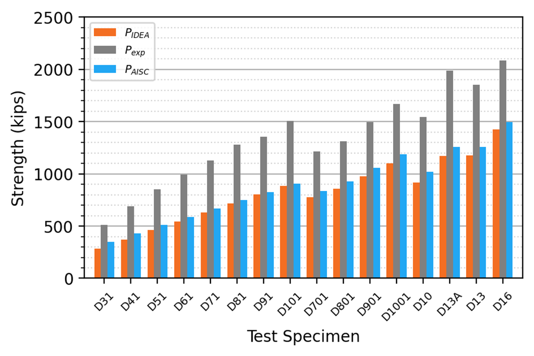
Figure 5 Comparison to the Bendigo et al. (1963) experimental investigation
Kulak and Fisher 1968
Kulak and Fisher (1968) performed tensile tests of long bolted splice connections consisting of a test plate bolted between two reaction plates with one line of A490 bolts of either 7/8 in. or 1-1/8 in. diameter. These tests were also included in the analysis to develop the reduction factors for length effects that appear in the AISC Specification (Tide 2010) but, unlike the tests by Bendigo et al. (1963), they used high strength plate.
The eight test specimens were dimensioned to fail in either bolt shear or plate rupture. Specimens J071, J131, and J171 failed in plate rupture, and specimens J072, J132, J172, J251, and J252 failed in bolt shear. The typical connection configuration for the specimens in the study is presented in Figure 6(a), and a three-dimensional view of the IDEA StatiCa model for specimen J171 is presented in Figure 6(b). The geometric and material properties for the test specimens are presented in Table 3.

Figure 6 Connection configuration for the Kulak and Fisher experimental investigation (Kulak and Fisher, 1968); (b) three-dimensional view of IDEA StatiCa model for specimen J171
The specimens were modeled in IDEA StatiCa. The strength of each connection was also computed according to traditional calculations using the AISC Specification equations with measured material and geometric properties. The results of the comparison between the experimental strength, Pexp, IDEA StatiCa strength, PIDEA, and the AISC Specification strength, PAISC, are presented in Table 4 and Figure 7.
The IDEA StatiCa strengths are conservative in comparison to the experimental tests for all cases. The IDEA StatiCa strengths align well with the AISC strengths for specimens J071, J072, J131, and J171, and are greater than the AISC strengths for specimens J132, J172, J251, and J252. The connection length is shorter than 38 in. for specimens J071 and J072, thus the 83.3% reduction in bolt shear capacity is not imposed. For specimens J131 and J171, the connection length is greater than 38 in., but the plate stiffness (i.e., the cross-sectional area) is relatively small. Thus, the IDEA StatiCa strengths align with or are slightly less than the AISC strengths for these cases. For specimens J132, J172, J251, and J252, the IDEA StatiCa strengths are greater than the AISC strengths because the plates are stiffer (i.e., larger cross-sectional areas).
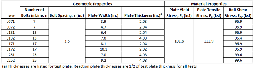
Table 3 Test specimen geometric and material properties for the Kulak and Fisher (1968) experimental investigation
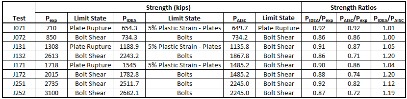
Table 4 Comparison to the Kulak & Fisher (1968) experimental investigation
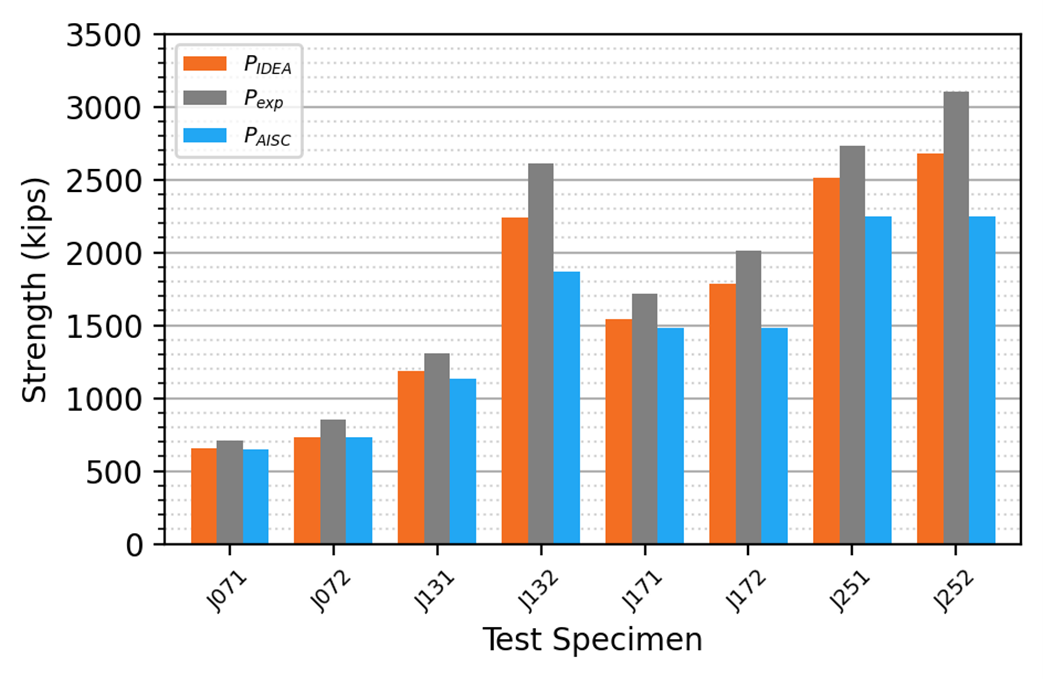
Figure 7 Comparison to the Kulak and Fisher (1968) experimental investigation
Long Welded Connections
To investigate the effect of non-uniform stress distribution along the connection length for a weld loaded in tension, a simple welded splice connection is used. The connection consists of a test plate welded between two reaction plates with fillet welds on each edge of the reaction plates. This configuration provides for a concentrically loaded weld group with a total of four weld lines in the connection. Note that for evaluating the effective weld length, the actual weld length of the connection is equal to the length of a single weld line in the group.
Weld sizes of 3/16 in. (Connection A) and 3/8 in. (Connection B) were investigated. The connections were dimensioned and material properties were chosen such that the limit state of weld rupture controlled over tensile yielding of the plates for the traditional calculations. The geometric and material properties used for the connections are presented in Table 5, and a three-dimensional view of Connection A with weld length equal to 18 in. is presented in Figure 8.
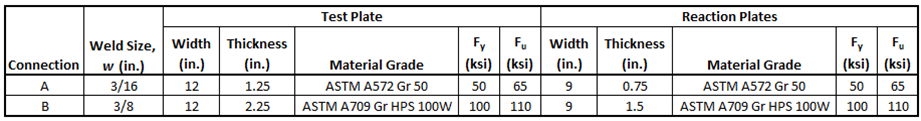
Table 5 Geometric and material properties for welded connections
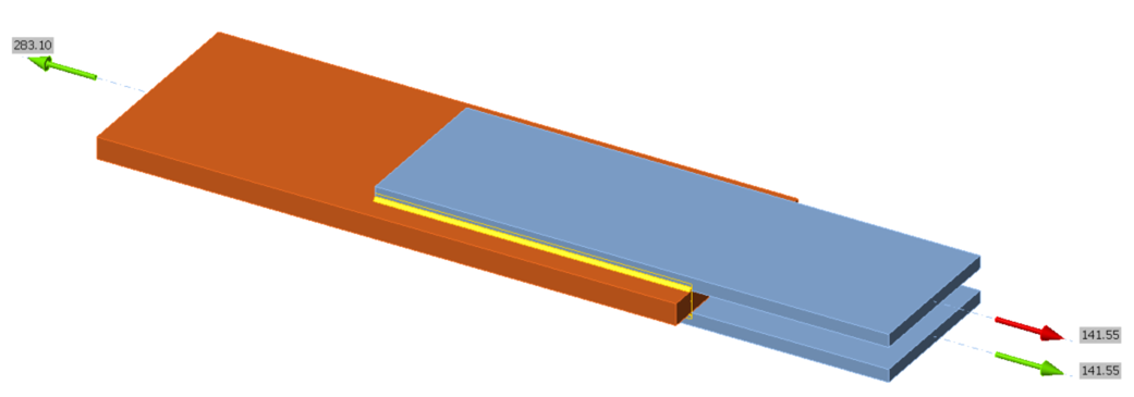
Figure 8 Three-dimensional view of a welded splice connection
For Connection A, fourteen weld lengths were tested, increasing in 4 in. increments between 10 in. and 62 in. For Connection B, thirteen weld lengths were tested, increasing in 10 in. increments between 10 in. and 130 in. A comparison of strength vs. weld length is presented in Figure 9 for Connection A and Figure 11 for Connection B. Stress distributions along the length of the weld are presented for varying weld lengths in Figure 10 for Connection A and Figure 12 for Connection B.
Connections A and B show similar behavior. For shorter weld lengths, the IDEA StatiCa strengths align well with the traditional calculations. However, the IDEA StatiCa strengths become conservative in comparison to the traditional calculations as weld length increases. The strengths from the traditional calculations plateau at a weld length of 300w, represented by a vertical dashed line in Figure 9 and Figure 11. The stress distribution along the length of the weld is nonlinear because IDEA StatiCa explicitly models the stiffness of the weld and plate. Because of this and because of the relatively conservative load-deformation relationship used in IDEA StatiCa for welds loaded in the longitudinal direction, the IDEA StatiCa strengths plateau at weld lengths much shorter than 300w. As shown in Figure 10 and Figure 12, shorter welds have a relatively uniform stress distribution, with slightly higher stresses occurring in the segments at the ends of the weld line. As weld length increases, the stress distribution along the weld line becomes significantly more non-uniform, with high stresses in the end segments and minimal stresses occurring close to the middle. The sharp change in the stress distribution seen in Figure 10 and Figure 12 for the longer welds is at the boundary between weld segments that remain elastic and weld segments that experience plastic deformations. The IDEA StatiCa limit for weld strength is established when the utilization of the most stressed weld segment reaches 100%. Therefore, for longer welds, there can be large portions of the weld line that experience low stress at the load associated with 100% utilization of the most highly stressed weld segment. The stress distribution profile in the IDEA StatiCa code check displays this non-linear behavior and should be examined when making engineering judgments regarding weld strength in IDEA StatiCa.
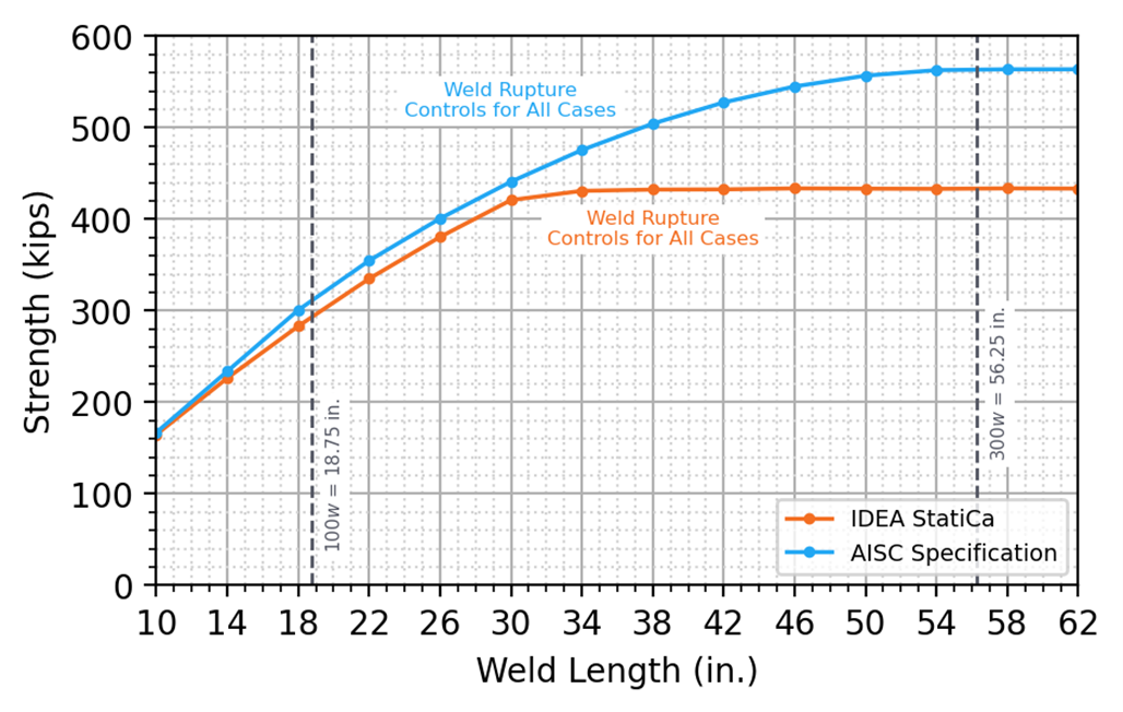
Figure 9 Strength vs. weld length for Connection A

Figure 10 Stress distributions along the length of the weld for Connection A with weld lengths of 18 in., 30 in., 42 in., and 54 in., Units are ksi
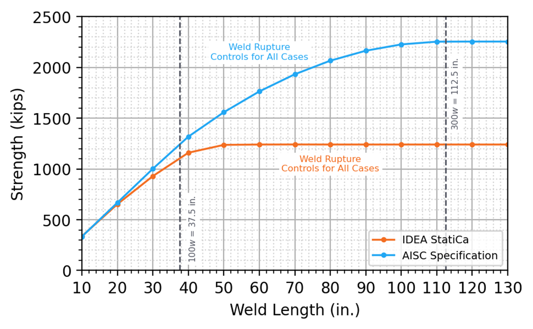
Figure 11 Strength vs weld length for Connection B
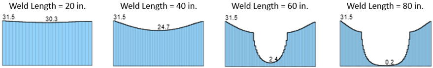
Figure 12 Stress distributions along the length of the weld for Connection B with weld lengths of 20 in., 40 in., 60 in., and 80 in., Units are ksi
Summary
This study evaluates the strength of long bolted and welded connections by traditional calculation methods used in US practice and IDEA StatiCa. Key observations from the study include:
For bolted connections:
- IDEA StatiCa explicitly models the stiffness of the bolts and plates; thus, length effects are captured naturally by the different required strengths for each bolt and not application of the simple reduction factor based only on connection length in the AISC Specification.
- The strength in IDEA StatiCa was found to be conservative in comparison to the strength by traditional calculations for most cases.
- The strength in IDEA StatiCa was found to be higher than the strength by traditional calculations for some cases where the connection length exceeded 38 in., and thicker plates were used.
- Strengths from IDEA StatiCa were found to be conservative in comparison to physical experiments performed by Bendigo et al. (1963) and Kulak and Fisher (1968).
For welded connections:
- IDEA StatiCa explicitly models the stiffness of the welds and plates; thus, length effects are captured naturally by the different required strengths for each segment of weld and not application of the simple reduction factors based only on the ratio of weld length to weld size in the AISC Specification.
- The strength in IDEA StatiCa was found to be conservative in comparison to the strength by traditional calculations for the cases investigated.
- The strength in IDEA StatiCa was found to be more conservative for longer weld lengths due to the effect of non-linear stress distribution among the weld segments and the relatively conservative load-deformation relationship for longitudinally loaded welds used in the IDEA StatiCa analyses.
References
AISC (2022), Specification for Structural Steel Buildings, American Institute of Steel Construction, Chicago, IL.
Bendigo, R. A., Hansen, R. M., and Rumpf, J. L. (1963). “Long Bolted Joints.” Journal of the Structural Division, ASCE, 89(6), 187–213.
CEN (2005), Eurocode 3: Design of Steel Structures, Comité Européen de Normalisation, Brussels, Belgium.
Kulak, G. L. and Fisher, J. W. (1968). “A514 Steel Joints Fastened by A490 Bolts.” Journal of the Structural Division, ASCE, 94(10), 2303-2324.
Kulak, G. L., Fisher, J. W., Struik, J. H. A. (2001) “Guide to Design Criteria for Bolted and Riveted Joints” Second Edition, American Institute of Steel Construction, Chicago, IL.
Miller, D. K. (2003). “Fillet Welds that are ‘Too Long.’” Modern Steel Construction, March.
Tide, R. H. (2010). "Bolt Shear Design Considerations." Engineering Journal, AISC, 47(1), 47-63.