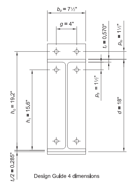
See AISC design examples, version 14.1, example II.B-4, page IIB-22
New project
Open IDEA software, select “Connection” to open steel CONNECTION design module
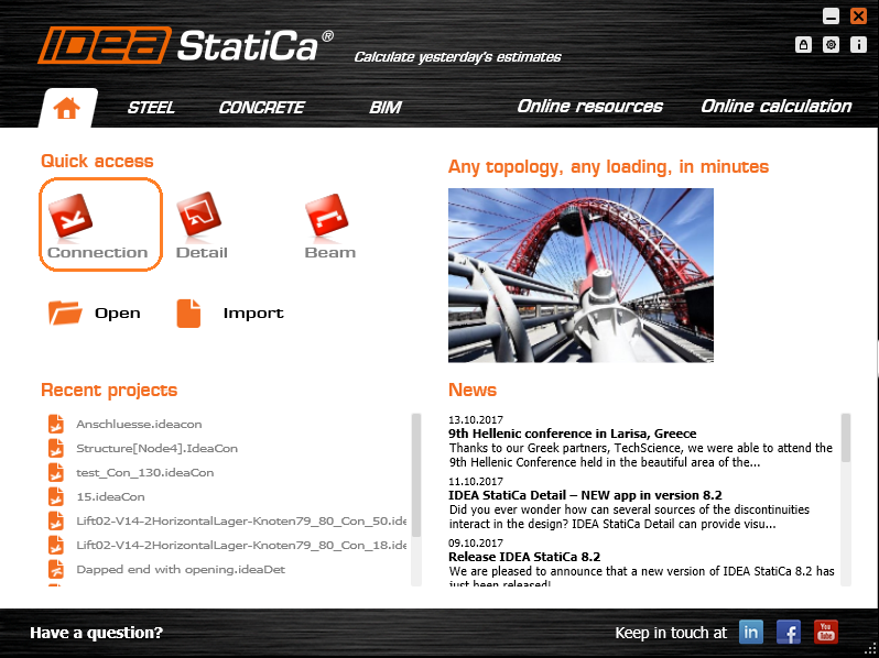
On “IDEA StatiCa CONNECTION” window, Select New to create New Project
On “New joint wizard” window, Select Frame 2D connection picture on the left
##MISSING IMAGE##
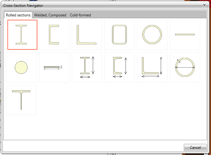
On “Select connection topology” window, Select connection in top row, second from the left
##MISSING IMAGE##
Geometry
On “IDEA StatiCa CONNECTION” window,
- Under Navigator, select Geometry to start the connection geometry input
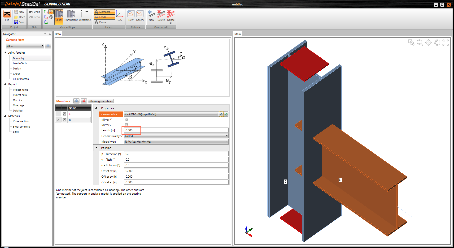
- Under Name, select C for column (you can rename the column)
- Under Cross-section, click on the double arrow symbol to open the “Cross-Section Navigator” window
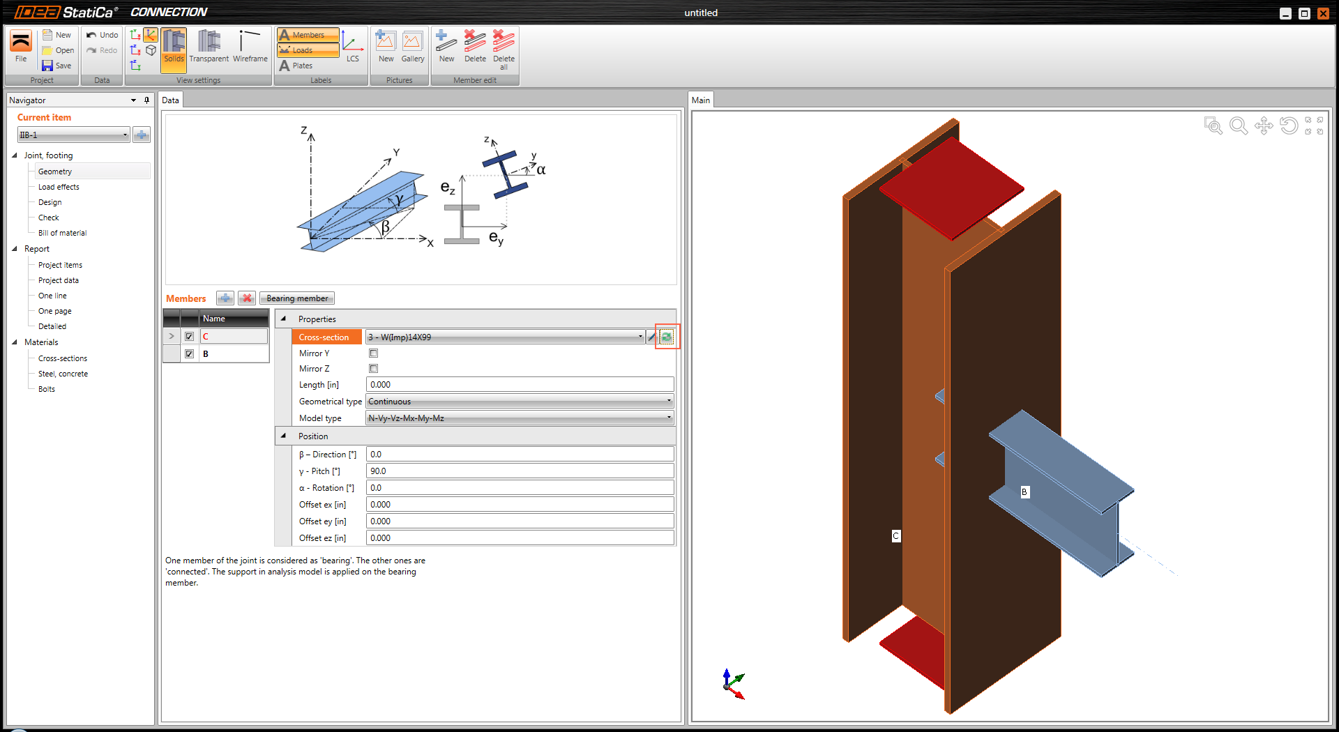
On “Cross Section Navigator” window,
- select wide flange W section
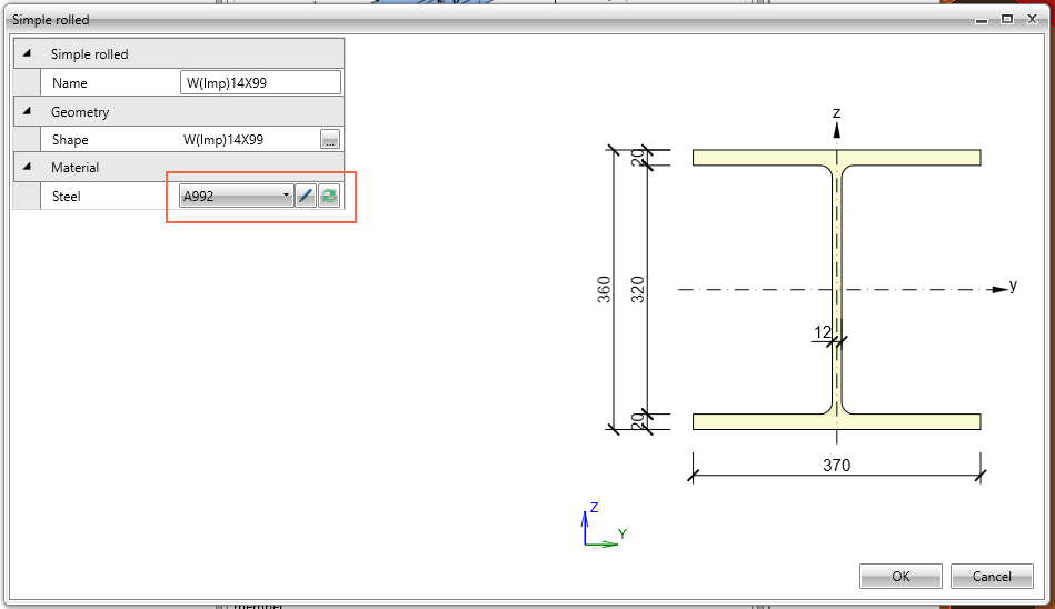
- On pop up window, select W(Imp)14x99, click OK to close the window
On “IDEA StatiCa CONNECTION” window, under Cross-section click on the pen symbol to enter column material property

On “Simple rolled” window, under Material, click on double arrow symbol to select A992
On “IDEA StatiCa CONNECTION” window, under “Name”, select B for beam and similar way as for the column select W18x50 and A992 material.
Keep “Length” of beam equal to zero. Using zero for length applies the load at the start of the beam (face of the column).
Loads
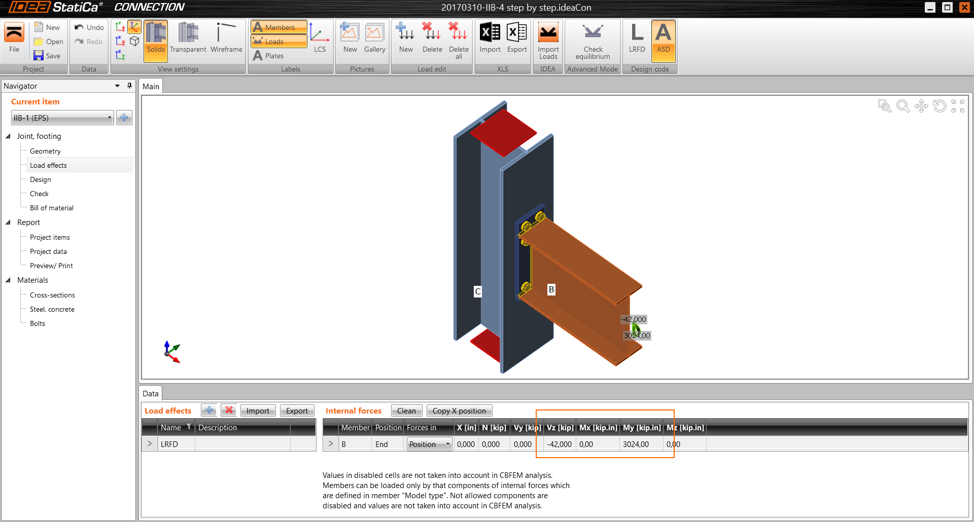
Under left pane Navigator, select Load effects. Change load combination name to LRFD (or pick your favorite name).
Select Forces in Position, Vy=-42 kips, My=3024 kip-in.
Watch graphical representation of the forces showing the actual direction of the loading
Design
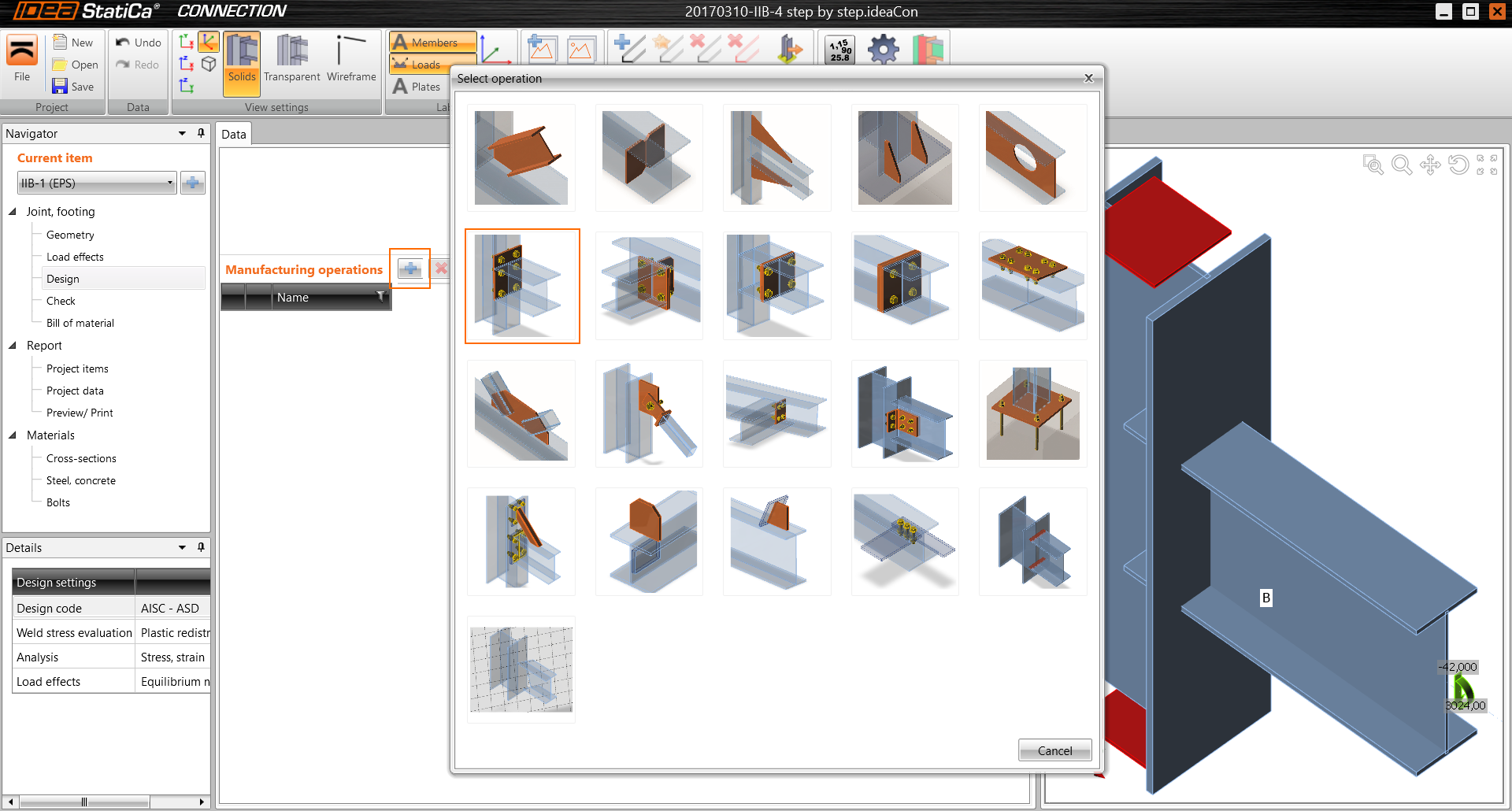
Under left pane Navigator, select Design, then to the right of “Manufacturing operations”, click on blue plus sign to add Manufacturing operation.
From a pop up “Select Operation” window, select “End plate”. Note that hint appears while hoovering your mouse over pictures.
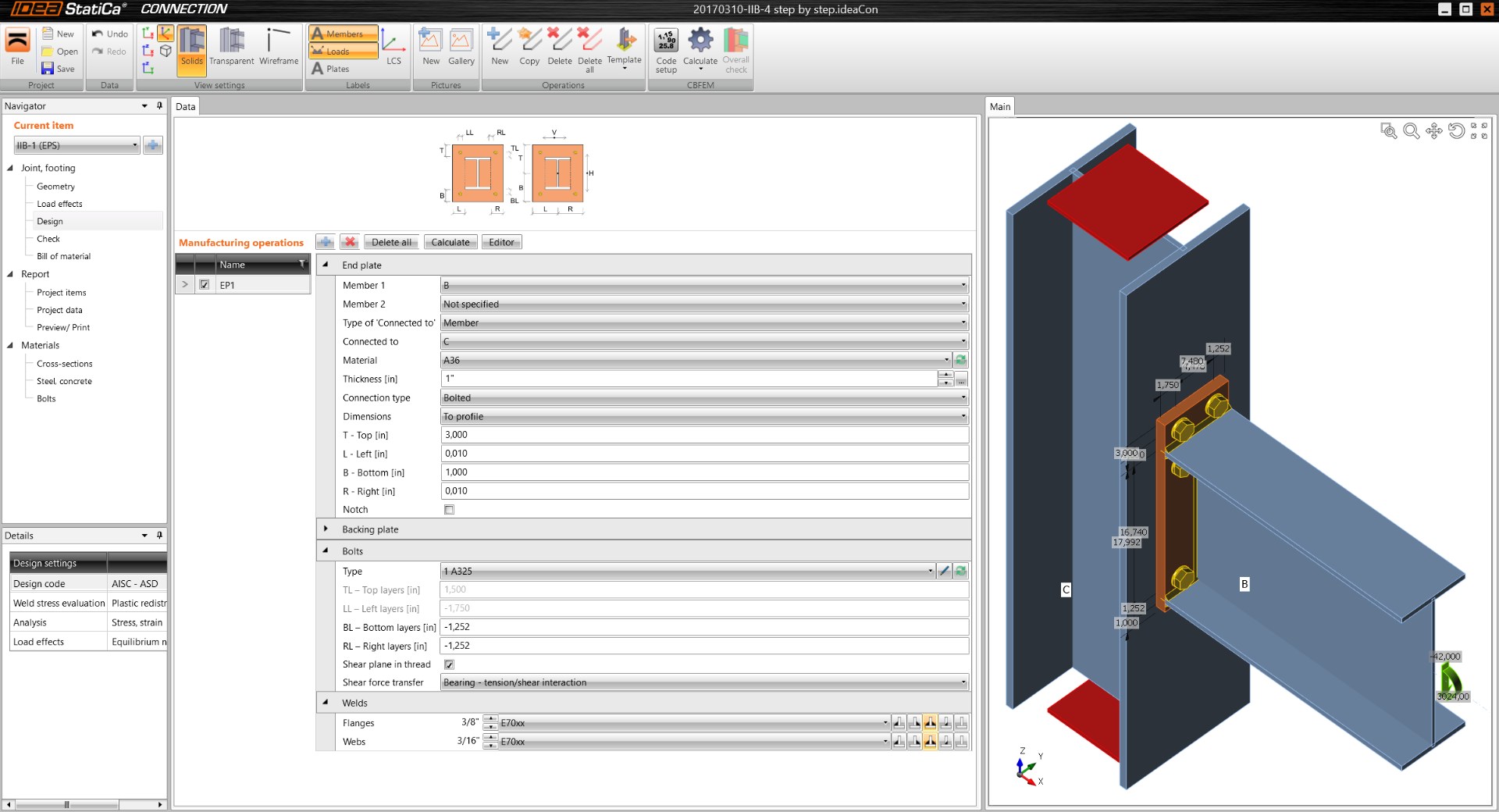
Populate End Plate properties per window below. As you input the values, watch the geometry on the right window change.
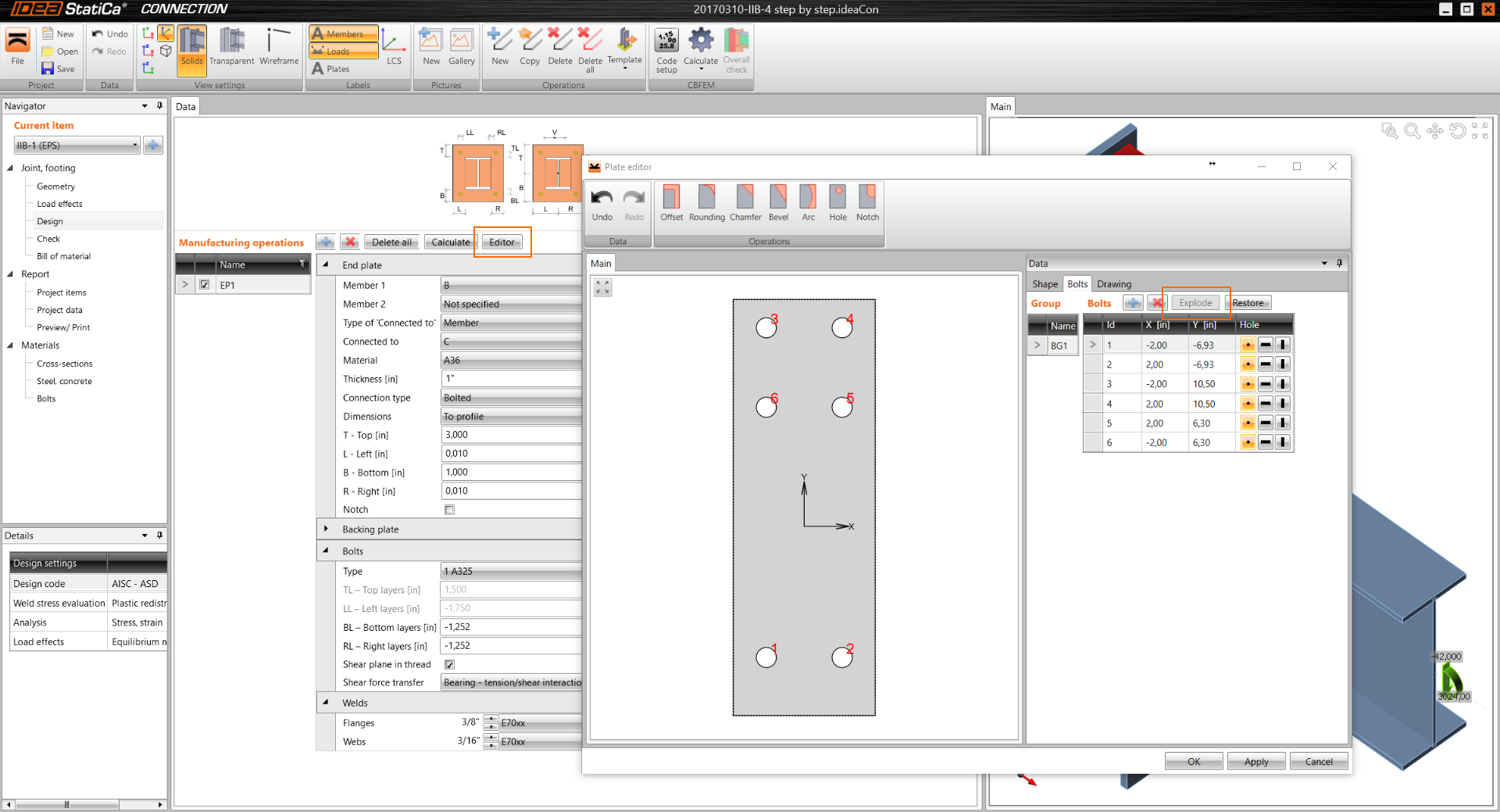
Customize bolt location.
To the right of “Manufacturing operations”, click on “Editor”. This opens “Plate editor” window.
Click on “Bolts”, then on “Explode”. Modify table to match table in a picture below. Use blue plus sign to add rows to the table.
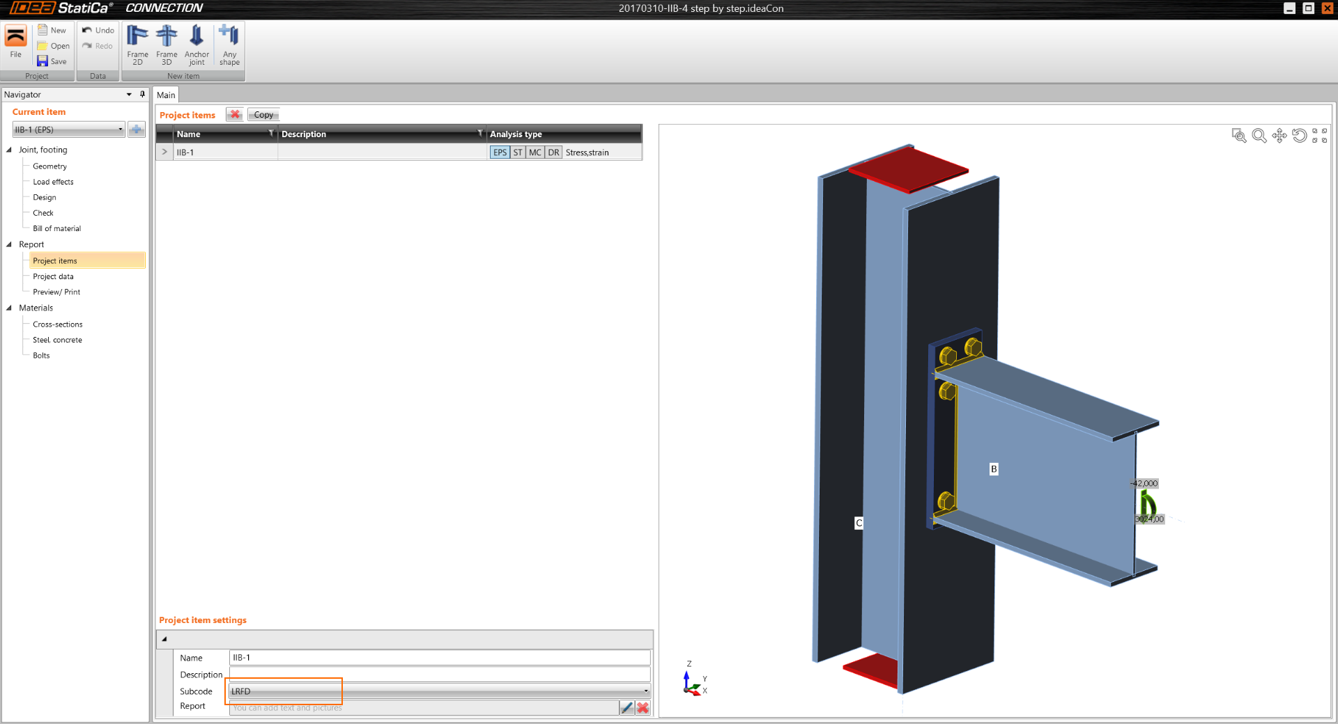
Under “Navigator” window, select “Report / Project items”. On Main window, under Subcode select “LRFD”
Analysis
Under “Navigator” window, select “Check”, then select “Calculate" toolbar from top bar.
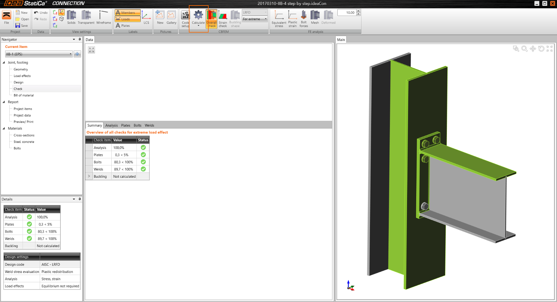
Results
Note that 4 items are listed under Analysis summary. All should have a green check mark, if not connection does not pass the check.
- Analysis 100% - meaning that analysis run correctly and 100% of load case has been used
- Plates 0.3 – meaning that plastic deformation of plates is 0.3%, which is less than code limit of 5%
- Bolts 82,4 – meaning that code Demand/Capacity ratio is 82,4%
- Welds 89,9 – meaning that code Demand/Capacity ratio is 89,9%
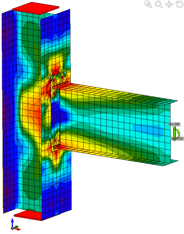
To view Equivalent stresses, on top menu bar, select “Equivalent stress”, “Mesh” & “Deformed”
Comparison
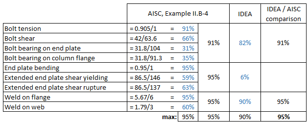
Table below shows, that AISC method yields overall Demand/Capacity (D/C) ration of 95%, IDEA yields D/C= 90%
Higher capacity of IDEA method is to be expected, since the Finite Element Method (FEM) used is more precise that approximate AISC capacity equations.
Bolt and Weld capacity can be directly compared with AISC.
Plate capacity in IDEA FEM is checked by comparing the amount of plastic deformation (<5%), whereas AISC method uses simplified capacity check. Therefor pass/fail results can be compared, but % comparison for plates is meaningless.