
Column base – Open section column in compression
Description
In this chapter, the Component-based Finite Element Method (CBFEM) of the column base under the steel open section column loaded in pure compression is verified on the component method (CM). The study is prepared for the column cross-section, dimension of base plate, grade of concrete, and dimensions of concrete block.
Component method
Three components are taken into account: column flange and web in compression, concrete in compression including grout, welds. Component column flange and web in compression is described in EN 1993-1-8:2005 Cl. 6.2.6.7. The concrete in compression including grout is modeled according to EN 1993-1-8:2005 Cl. 6.2.6.9 and EN 1992-1-1:2005 Cl. 6.7. Two iterations of effective area are used to determine the resistance.
The weld is designed around the column cross-section; see EN 1993-1-8:2005 Cl. 4.5.3.2(6). The thickness of the weld on the flanges is selected the same as the thickness of the weld on the web. Shear force is transferred only by welds on the web, and plastic stress distribution is considered.
Base plate under HEB 240
This study is focused on the component concrete in compression including grout. An example of calculation is shown below for the concrete block with dimensions a' = 1000 mm, b' = 1500 mm, h = 800 mm from concrete grade C20/25 with base plate with dimensions a = 330 mm, b = 440 mm, t = 20 mm from steel grade S235; see Fig. 8.1.2.
The joint stength of the concrete is calculated under the effective area in compression around the cross-section; see Fig. 8.1.1, iterating in two steps.
For 1st step it is:
\[ f_{jd} = \frac{\beta_j k_j f_{ck}}{\gamma_c} = \frac{0.67 \cdot 2.908 \cdot 20}{1.5} = 26 \textrm{ MPa} \]
\[ c = t \sqrt{\frac{f_y}{3f_{jd} \gamma_{M0}}} = 20 \sqrt{\frac{235}{3 \cdot 26 \cdot 1.0}} = 35 \textrm{ mm} \]
\[ l_{eff} = b+2c = 240+2\cdot35=310 \textrm{ mm} \]
\[ b_{eff} = t_f+2c = 17+2\cdot35=87\textrm{ mm} \]
and for 2nd step it is:
\[ f_{jd} = \frac{\beta_j k_j f_{ck}}{\gamma_c} = \frac{0.67 \cdot 3 \cdot 20}{1.5} = 27 \textrm{ MPa} \]
\[ c = t \sqrt{\frac{f_y}{3f_{jd} \gamma_{M0}}} = 20 \sqrt{\frac{235}{3 \cdot 27 \cdot 1.0}} = 34 \textrm{ mm} \]
\[ l_{eff} = b+2c = 240+2\cdot35=308 \textrm{ mm} \]
\[ b_{eff} = t_f+2c = 17+2\cdot35=85\textrm{ mm} \]
\[A_{eff} = 63463 \textrm{ mm}^2\]
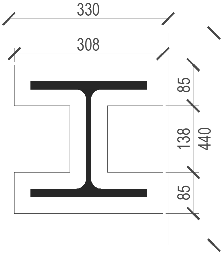
Fig. 8.1.1 Effective area under the base plate
The normal force resistance of the base plate by CM is
\[N_{Rd} = A_{eff} \cdot f_{jd} = 63436 \cdot 27 = 1701 \textrm{ kN} \]
The stresses calculated by CBFEM are presented in Fig. 8.1.2. The normal compressive force resistance of the base plate by CBFEM is 1683 kN.
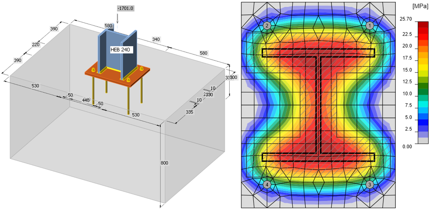
Fig. 8.1.2 Geometry of concrete block and normal stresses under baseplate loaded by normal force only
Sensitivity study
The results of CBFEM software were compared with the results of the component method. The comparison was focused on the resistance and the critical component. Studied parameters are size of the column, dimensions of the base plate, concrete grade, and dimensions of the concrete pad. The column cross-sections are HEB 200, HEB 300, and HEB 400. The base plate width and length are chosen as 100 mm, 150 mm and 200 mm larger than the column section, the base plate thickness 15 mm, 20 mm, and 25 mm. The concrete block from grade C16/20, C25/30, and C35/45 of height 800 mm with width and length larger than the dimensions of the base plate by 200 mm, 300 mm, and 400 mm. The input parameters are summarized in Tab. 8.1.1. The fillet welds around the column cross-section have the throat thickness a = 8 mm.
Tab. 8.1.1 Selected parameters
| Column section | HEB 200 | HEB 300 | HEB 400 |
| Base plate offset | 100 mm | 150 mm | 200 mm |
| Base plate thickness | 15 mm | 20 mm | 25 mm |
| Concrete grade | C16/20 | C25/30 | C35/45 |
| Concrete pad offset | 200 mm | 300 mm | 400 mm |
The resistances determined by CM are in Tab. 8.1.2. One parameter was changed, and the others were held constant at the middle value. NRd is the resistance of component concrete in compression including grout Fc,fc,Rd is the resistance of component column flange and web in compression and Fc,weld is the resistance of welds considering uniform distribution of stress. The joint coefficient βj = 0,67 was used.
Table 8.1.2 Results of component method
| Column | B.p. offset [mm] | B.p. thickness [mm] | Concrete | C.b. offset [mm] | NRd [kN] | 2.Fc,fc,Rd [kN] | Fc,weld [kN] |
| HEB 200 | 150 | 20 | C25/30 | 300 | 1753 | 1632 | 2454 |
| HEB 300 | 150 | 20 | C25/30 | 300 | 2352 | 3126 | 3466 |
| HEB 400 | 150 | 20 | C25/30 | 300 | 2579 | 4040 | 3822 |
| HEB 300 | 100 | 20 | C25/30 | 300 | 2296 | 3126 | 3466 |
| HEB 300 | 200 | 20 | C25/30 | 300 | 2408 | 3126 | 3466 |
| HEB 300 | 150 | 15 | C25/30 | 300 | 1909 | 3126 | 3466 |
| HEB 300 | 150 | 25 | C25/30 | 300 | 2795 | 3126 | 3466 |
| HEB 300 | 150 | 20 | C16/20 | 300 | 1789 | 3126 | 3466 |
| HEB 300 | 150 | 20 | C35/45 | 300 | 2908 | 3126 | 3466 |
| HEB 300 | 150 | 20 | C25/30 | 200 | 2064 | 3126 | 3466 |
| HEB 300 | 150 | 20 | C25/30 | 400 | 2517 | 3126 | 3466 |
The model in CBFEM was loaded by the compressive force until the concrete block was very close to 100 %. The same approach was used to get the resistance of welds Fc,weld.
Table 8.1.3 Results of CBFEM
| Column | B.p. offset [mm] | B.p. thickness [mm] | Concrete grade | C.b. offset [mm] | Concrete block [kN] | Fc,weld or Fc,Rd [kN] |
| HEB 200 | 150 | 20 | C25/30 | 300 | 1565 | 1835 |
| HEB 300 | 150 | 20 | C25/30 | 300 | 2380 | 3205 |
| HEB 400 | 150 | 20 | C25/30 | 300 | 2710 | 3650 |
| HEB 300 | 100 | 20 | C25/30 | 300 | 2385 | 3205 |
| HEB 300 | 200 | 20 | C25/30 | 300 | 2420 | 3205 |
| HEB 300 | 150 | 15 | C25/30 | 300 | 1870 | 3204 |
| HEB 300 | 150 | 25 | C25/30 | 300 | 2915 | 3204 |
| HEB 300 | 150 | 20 | C16/20 | 300 | 1850 | 3205 |
| HEB 300 | 150 | 20 | C35/45 | 300 | 2975 | 3205 |
| HEB 300 | 150 | 20 | C25/30 | 200 | 2380 | 3205 |
| HEB 300 | 150 | 20 | C25/30 | 400 | 2420 | 3205 |
Summary
Verification of CBFEM to CM for base plate loaded in compression is shown in Fig. 8.1.3. The dashed lines correspond to the 110 % and 90 % value of resistance. The difference is up to 14 % due to more accurate evaluation of the design bearing strength of the joint and effective area in CBFEM.
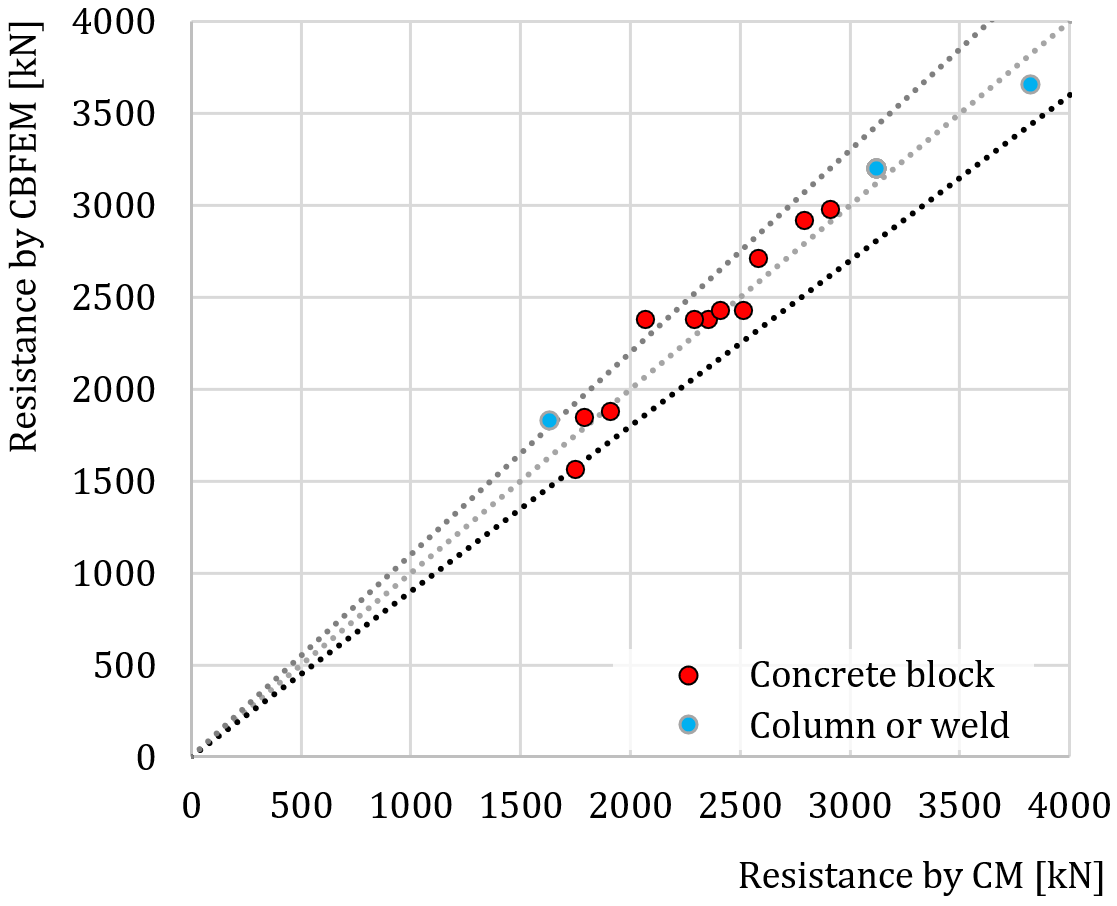
Fig. 8.1.3 Verification of CBFEM to CM for base plate loaded in compression
Benchmark case
Input
Column cross-section
- HEB 240
- Steel S235
Base plate
- Thickness 20 mm
- Offsets top 100 mm, left 45 mm
- Steel S235
Foundation concrete block
- Concrete C20/25
- Offset 335 mm, 530 mm
- Depth 800 mm
- Grout thickness 30 mm
Anchor bolt
- M20 8.8
Output
- Axial force resistance Nj.Rd = −1683 kN