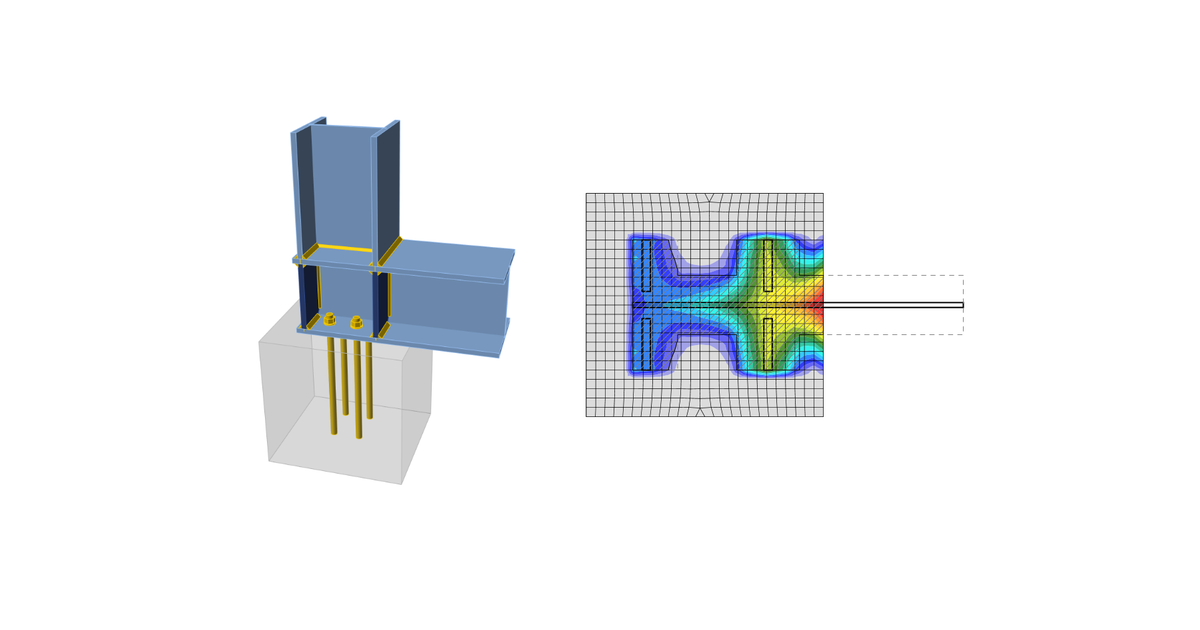
Code-check of concrete block according to Indian standards
Concrete in bearing
Two options for checking of concrete in bearing are available:
- According to IS 800, Cl. 7.4
- According to IS 456, Cl. 34.4
Concrete in bearing checked according to IS 800, Cl. 7.4
The maximum bearing pressure should not exceed the bearing strength equal to \(0.6 f_{ck}\), where \(f_{ck}\) is the characteristic cube strength of concrete. The strength of grout is assumed to be higher than that of concrete foundation. Cl. 7.4.3.1 provides the formula for the minimum thickness of column bases:
\[ t_s = \sqrt{2.5 w c^2 \gamma_{m0} / f_y} > t_f \]
where:
- \(w\) – uniform pressure from below on the slab base under the factored load axial compression
- \(c\) – overlap of the column base over the column
- \(f_y\) – yield strength of the column base
- \(t_f\) – column flange thickness
- \(\gamma_{m0} = 1.1\) – partial safety factor for resistance governed by yielding – IS 800, Table 5; editable in Code setup
The formula can be rewritten to determine the overlap with the assumption that \(w = 0.6 f_{ck}\):
\[ c = t_s \sqrt{\frac{f_y}{1.5 f_{ck} \gamma_{m0}}} \]
The area \(A_{c,eff}\) is determined by offsetting the column (with stiffeners) cross-sectional area intersecting the base plate by overlap \(c\). Another area, \(A_{FEM,eff}\) determining the area in contact between the base plate and concrete foundation (grout) by finite element analysis. The area resisting the compressive forces, \(A_{eff}\) is intersection of these two areas, \(A_{c,eff}\) and \(A_{FEM,eff}\). Bearing strength \(0.6 f_{ck}\) on this area \(A_{eff}\) is assumed at the ultimate limit state.
The check of concrete in the bearing is performed in a form of stresses:
\[ \sigma_c \le w \]
where:
- \(\sigma_c = \frac{N_c}{A_{eff}}\) – average bearing stress below the base plate
- \(N_c\) – compressive force
- \(w = 0.6 f_{ck}\) – bearing resistance of the concrete
Concrete in bearing checked according to IS 456, Cl. 34.4.
The maximum bearing pressure should not exceed the bearing strength equal to \(0.45 f_{ck} \cdot \min \left \{ \sqrt{\frac{A_1}{A_2}}, \, 2 \right \} \), where:
- \(f_{ck}\) – characteristic cube strength of concrete; strength of grout is assumed higher than that of concrete foundation
- \(A_1\) – supporting area taken as the area of the lower base of the largest frustum of a pyramid or cone contained wholly within the footing and having for its upper base, the area actually loaded and having side slope of one vertical to two horizontal
- \(A_2\) – bearing area determined by finite element analysis (equal to \(A_{FEM,eff}\))
The check of concrete in the bearing is performed in a form of stresses:
\[ \sigma_c \le w \]
where:
- \(\sigma_c = \frac{N_c}{A_{2}}\) – average bearing stress below the base plate
- \(N_c\) – compressive force
- \(w = 0.45 f_{ck} \cdot \min \left \{ \sqrt{\frac{A_1}{A_2}}, \, 2 \right \}\) – bearing resistance of the concrete
Transfer of shear
The shear action at the base plate is assumed to be transferred from the column to the concrete foundation by:
- Friction between base plate and concrete/grout
- Shear lug
- Anchor bolts
Anchors
The tensile forces in anchors include prying forces and are determined by finite element analysis.
Anchors are not checked in the software.


