Normtoetsing van betonblok volgens Indiase normen
Beton op druk
Er zijn twee opties beschikbaar voor de normtoetsing van beton op druk:
- Volgens IS 800, Cl. 7.4
- Volgens IS 456, Cl. 34.4
Beton op druk getoetst volgens IS 800, Cl. 7.4
De maximale drukspanning mag de druksterkte gelijk aan \(0.6 f_{ck}\) niet overschrijden, waarbij \(f_{ck}\) de karakteristieke kubusdruksterkte van het beton is. De sterkte van de grout wordt verondersteld hoger te zijn dan die van de betonnen fundering. Cl. 7.4.3.1 geeft de formule voor de minimale dikte van kolomvoeten:
\[ t_s = \sqrt{2.5 w c^2 \gamma_{m0} / f_y} > t_f \]
waarbij:
- \(w\) – gelijkmatige druk van onderen op de voetplaat onder de maatgevende belasting axiale druk kracht
- \(c\) – uitkraging van de kolomvoet over de kolom
- \(f_y\) – vloeigrens van de kolomvoet
- \(t_f\) – dikte van de kolomflens
- \(\gamma_{m0} = 1.1\) – partiële veiligheidsfactor voor weerstand bepaald door vloeien – IS 800, Tabel 5; aanpasbaar in de norminstellingen
De formule kan worden herschreven om de uitkraging te bepalen met de aanname dat \(w = 0.6 f_{ck}\):
\[ c = t_s \sqrt{\frac{f_y}{1.5 f_{ck} \gamma_{m0}}} \]
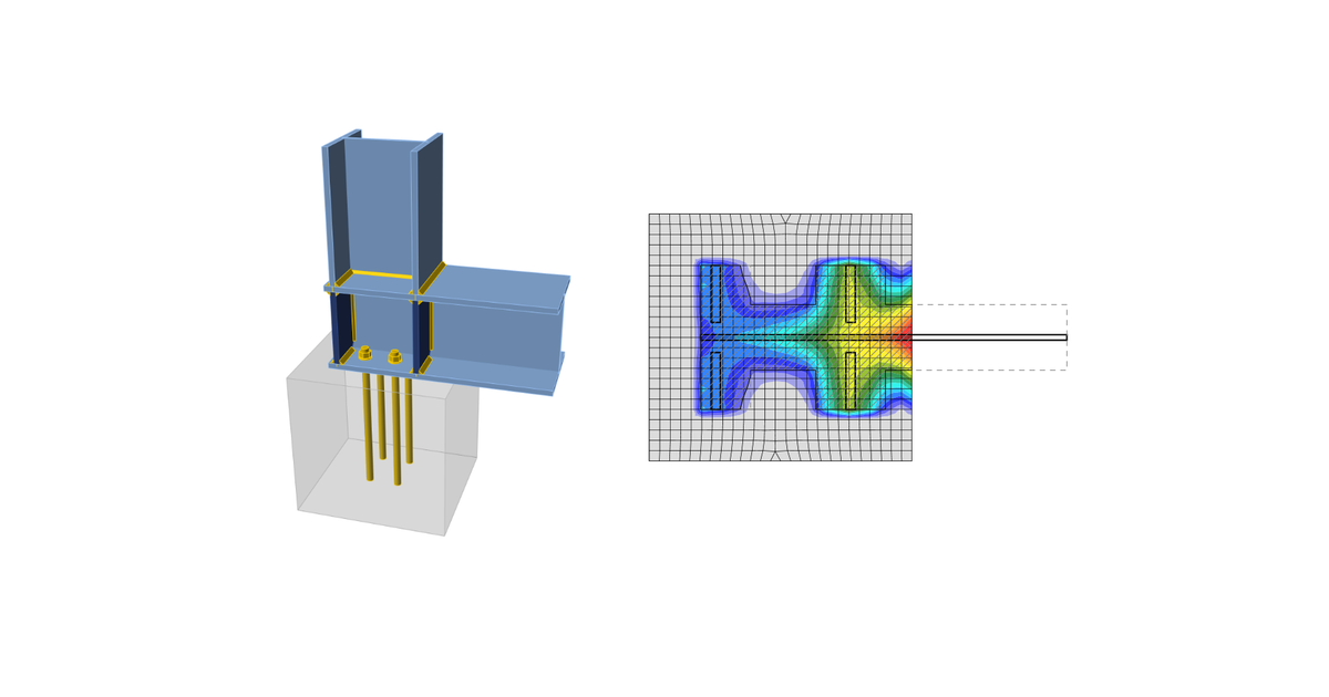
Het oppervlak \(A_{c,eff}\) wordt bepaald door het doorsnede-oppervlak van de kolom (met verstijvers) dat de voetplaat snijdt te vergroten met uitkraging \(c\). Een ander oppervlak, \(A_{FEM,eff}\), bepaalt het contactoppervlak tussen de voetplaat en de betonnen fundering (grout) via de Eindige Elementen Methode. Het oppervlak dat de drukkrachten weerstaat, \(A_{eff}\), is de doorsnede van deze twee oppervlakken, \(A_{c,eff}\) en \(A_{FEM,eff}\). Bij de uiterste grenstoestand wordt een druksterkte van \(0.6 f_{ck}\) op dit oppervlak \(A_{eff}\) aangenomen.
De normtoetsing van beton op druk wordt uitgevoerd in de vorm van spanningen:
\[ \sigma_c \le w \]
waarbij:
- \(\sigma_c = \frac{N_c}{A_{eff}}\) – gemiddelde drukspanning onder de voetplaat
- \(N_c\) – druk kracht
- \(w = 0.6 f_{ck}\) – druksterkte van het beton
Beton op druk getoetst volgens IS 456, Cl. 34.4.
De maximale drukspanning mag de druksterkte gelijk aan \(0.45 f_{ck} \cdot \min \left \{ \sqrt{\frac{A_1}{A_2}}, \, 2 \right \} \) niet overschrijden, waarbij:
- \(f_{ck}\) – karakteristieke kubusdruksterkte van het beton; de sterkte van de grout wordt verondersteld hoger te zijn dan die van de betonnen fundering
- \(A_1\) – ondersteuningsoppervlak genomen als het oppervlak van de onderste basis van de grootste afgeknotte pyramide of kegel die volledig binnen de fundering valt en als bovenste basis het werkelijk belaste oppervlak heeft, met een zijhelling van één verticaal op twee horizontaal
- \(A_2\) – drukoppervlak bepaald door de Eindige Elementen Methode (gelijk aan \(A_{FEM,eff}\))
De normtoetsing van beton op druk wordt uitgevoerd in de vorm van spanningen:
\[ \sigma_c \le w \]
waarbij:
- \(\sigma_c = \frac{N_c}{A_{2}}\) – gemiddelde drukspanning onder de voetplaat
- \(N_c\) – druk kracht
- \(w = 0.45 f_{ck} \cdot \min \left \{ \sqrt{\frac{A_1}{A_2}}, \, 2 \right \}\) – druksterkte van het beton
Overdracht van afschuiving
De afschuivingskracht op de voetplaat wordt verondersteld te worden overgedragen van de kolom naar de betonnen fundering door:
- Wrijving tussen voetplaat en beton/grout
- Afschuif deuvel
- Ankerbouten