Bolts
The initial stiffness and design resistance of bolts in shear are in CBFEM modeled according to Cl. 3.6 and 6.3.2 in EN 1993-1-8. The spring representing bearing and tension has a bi-linear force-deformation behavior with an initial stiffness and design resistance according to Cl. 3.6 and 6.3.2 in EN 1993-1-8.
Design tension resistance of bolt (EN 1993-1-8 – Table 3.4):
\[ F_{t,Rd}=0.9 f_{ub} A_s / \gamma_{M2} \]
Design punching shear resistance of bolt head or nut (EN 1993-1-8 – Table 3.4):
\[ B_{p,Rd} = 0.6 \pi d_m t_p f_u / \gamma_{M2} \]
Design shear resistance per one shear plane (EN 1993-1-8 – Table 3.4):
\[ F_{v,Rd} = \alpha_v f_{ub} A_s / \gamma_{M2} \]
Design shear resistance can be multiplied by reduction factor βp if packing is present (EN 1993-1-8 – Cl. 3.6.1. (12)), and this option is selected in Code setup.
Design bearing resistance of plate (EN 1993-1-8 – Table 3.4):
\( F_{b,Rd} = k_1 \alpha_b f_u d t / \gamma_{M2} \) for standard holes
\( F_{b,Rd} = 0.6 k_1 \alpha_b f_u d t / \gamma_{M2} \) for slotted holes
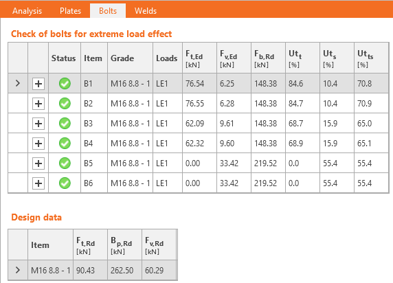
Utilization in tension [%]:
\[ Ut_t = \frac{F_{t,Ed}}{\min (F_{t,Rd},\, B_{p,Rd})} \]
Utilization in shear [%]:
\[ Ut_s = \frac{F_{v,Ed}}{\min (F_{v,Rd},\, F_{b,Rd})} \]
Interaction in shear and tension [%]:
\[ Ut_{ts}=\frac{F_{v,Ed}}{F_{v,Rd}}+\frac{F_{t,Ed}}{1.4 F_{t,Rd}} \]
where:
- As – tensile stress area of the bolt
- fub – ultimate tensile strength of the bolt
- dm – mean of the across points and across flats dimensions of the bolt head or the nut, whichever is smaller
- d – bolt diameter
- tp – plate thickness under the bolt head/nut
- fu – ultimate steel strength
- αv = 0.6 for grades 4.6, 5.6, 8.8 and 0.5 for grades 4.8, 5.8, 6.8, 10.9
- \( k_1 = \min \left \{2.8 \frac{e_2}{d_0}-1.7, \, 1.4 \frac{p_2}{d_0}-1.7, \, 2.5 \right \} \) – factor from Table 3.4
- \(\alpha_b = 1.0\) if the bearing check with \(\alpha_b\) is deactivated in Code setup; if the check is activated, the value of αb is determined according to EN 1993-1-8 – Table 3.4: \( \alpha_b = \min \left \{ \alpha_d, \, \frac{f_{ub}}{f_u}, \, 1.0 \right \} \)
- \(\alpha_d = \min \left \{ \frac{e_1}{3 d_0}, \, \frac{p_1}{3 d_0}-\frac{1}{4} \right \} \)
- e1, e2 – edge distances in the direction of the load and perpendicular to the load
- p1, p2 – bolt pitches in the direction of the load and perpendicular to the load
- Ft,Ed – design tensile force in bolt
- Fv,Ed – design shear force in bolt
- γM2 – safety factor (EN 1993-1-8 – Table 2.1; editable in Code setup)
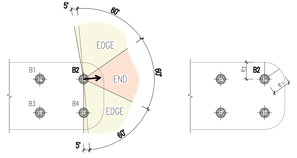
Edge distances used for bolt bearing resistance must be relevant for general plate geometries, plates with openings, cutouts, etc.
The algorithm reads the real direction of the resulting shear force vector in a given bolt and then calculates the distances needed for the bearing check.
The end (e1) and edge (e2) distances are determined by dividing the plate contour into three segments. The "end segment" is indicated by a 60° range in the direction of the force vector. The "edge segments" are defined by two 65° ranges perpendicular to the force vector. The shortest distance between a bolt and an edge in the relevant segment is then taken as an end, or edge distance.
The algorithm evaluates all plates connected by the bolt—the connecting plates (e.g., a splice plate), the member plates (e.g., a top flange), and the shortest distance is used.
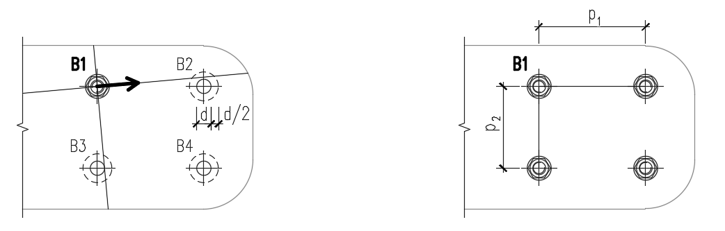
The spacing distances between bolt holes (p1; p2) are determined by virtually enlarging the surrounding bolt holes by half their diameter, then drawing two lines in the direction and perpendicular to the shear force vector. When these lines intersect with virtually enlarged bolt holes, then the distances to these bolts are considered as p1 and p2 in the calculation.
If the lines don't intersect with the visually closest bolt (even though the line misses the bolt closely), this bolt is neglected. If the lines don't intersect with any bolt, an infinite value is used.
Bolts connecting thin-walled plates
Bolts connecting plates thinner than 3 mm, the provisions of EN 1993-1-3, Table 8.4 are used instead.
Bearing resistance:
\[F_{b,Rd}=2.5\cdot \alpha_b \cdot k_t \cdot f_u \cdot d \cdot t /\gamma_{M2}\]
where:
- \( \alpha_b=\min \left \{ 1.0, e_1/(3d) \right \} \)
- \(k_t = (0.8 t+1.5)/2.5 \) for 0.75 mm \(\le t \le\) 1.25 mm; \( k_t=1.0 \) for \(t>1.25\) mm
- \(f_u\) – ultimate strength of the connected plate
- \(d\) – bolt diameter
- \(t\) – thickness of the connected plate
- \(\gamma_{M2}\) – partial safety factor for connections editable in Code setup; by default \(\gamma_{M2}=1.25\)
Shear resistance, tension resistance, interaction of tension and shear, and punching shear resistance are determined according to EN 1993-1-8 – the same way as bolts connecting plates with a thickness higher than 3 mm.
Range of validity:
\[e_1 \ge 1.0 d_0 \]
\[p_1 \ge 3 d_0 \]
\[e_2 \ge 1.5 d_0 \]
\[p_2 \ge 3 d_0 \]
\[ f_u \le 550 \textrm{ MPa} \]
\[3 \textrm{ mm} > t \ge 0.75 \textrm{ mm} \]
Minimum bolt size: M6 – checked as \(d \ge 6\) mm
Bolt strength grades: 4.6 – 10.9 – checked as \(f_u \le 1000\) MPa
The bolts will be marked as failing if they are outside the range of validity.
Preloaded bolts
Design slip resistance per bolt grade 8.8 or 10.9 (EN 1993-1-8, Cl. 3.9 – Equation 3.8):
\[ F_{s,Rd} =\frac{k_s n \mu (F_{p,C} - 0.8 F_{t,Ed})}{\gamma_{M3}} \]
The preload (EN 1993-1-8 – Equation 3.7)
Fp,C = 0.7 fub As
The preloading force factor 0.7 can be modified in Code setup.
Utilization [%]:
\[ Ut_s = \frac{V}{F_{s,Rd}} \]
where:
- As – tensile stress area of the bolt
- fub – ultimate tensile strength
- ks – a coefficient (EN 1993-1-8 – Table 3.6; ks = 1 for normal round holes, ks = 0.63 for slotted holes)
- μ – slip factor editable in Code setup (EN 1993-1-8 – Table 3.7)
- n – number of the friction surfaces. Check is calculated for each friction surface separately
- γM3 – safety factor (EN 1993-1-8 – Table 2.1; editable in Code setup – recommended values are 1.25 for ultimate limit state and 1.1 for serviceability limit state design)
- V – design shear force in bolt
- Ft,Ed – design tensile force in bolt
If slip of preloaded bolts is checked for serviceability limit state, they should be afterward switched to "bearing – tension/shear interaction" and checked for the ultimate limit state.
Fire design
Preloaded bolts are assumed to slip, so that the checks of bearing bolts and preloaded bolts are the same.
Checks at fire and at ambient temperature are both performed and the minimum is selected as a design load resistance.
At elevated temperature, bolts are checked according to EN 1993-1-2, Annex D. Note that the area reduced by threads is always used in shear check according to D1.1.1.
Detailing
Detailing checks of bolts are performed if the option is selected in Code setup. Dimensions from bolt center to plate edges and between bolts are checked. Edge distance e = 1.2 and spacing between bolts p = 2.2 are recommended in Table 3.3 in EN 1993-1-8. User can modify both values in Code setup.
Minimum plate thickness of plates connected by bolts is checked. Plate thickness must be higher than 0.75 mm according to EN 1993-1-3 – Table 8.4.
Information is issued if ductility and rotation capacity requirements for bolted connection in tension according to EN 1993-1-8 – 6.4.2 are not met. If bolt is loaded predominantly in tension, the thinner connected plate should satisfy:
\[t \le 0,36d \sqrt{\frac{f_{ub}}{f_y}}\]
The default sizes of bolt assemblies are according to EN ISO 4014 – Hexagon bolt heads, EN ISO 4032 – Hexagon regular nuts, and EN ISO 7089 – Plain washers – Normal series – Product grade A.
Get 14 days of full access, completely free.
Check out IDEA StatiCa for free