Steel joint analysis model
The CBFEM method (Component Based Finite Element Model) enables fast analysis of joints of several shapes and configurations. The model consists of members to which the load is applied and manufacturing operations (including stiffening members), which serve to connect members to each other. Members must not be confused with manufacturing operations because their cut edges are connected via rigid links to the connection node, so they are not deformed properly if used instead of manufacturing operations (stiffening members).
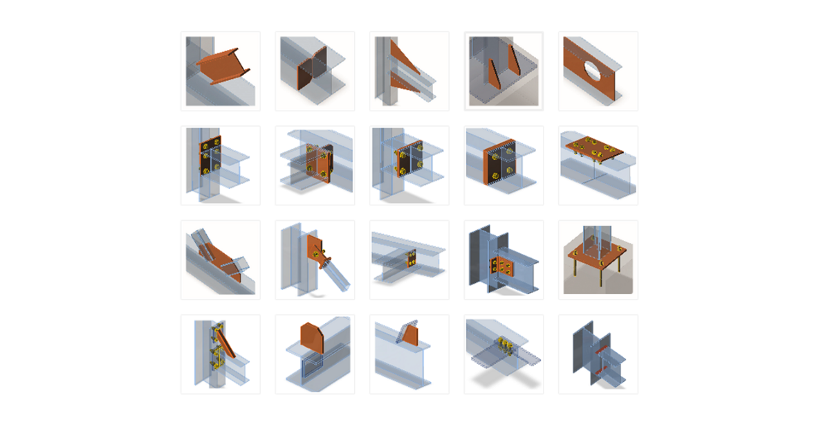
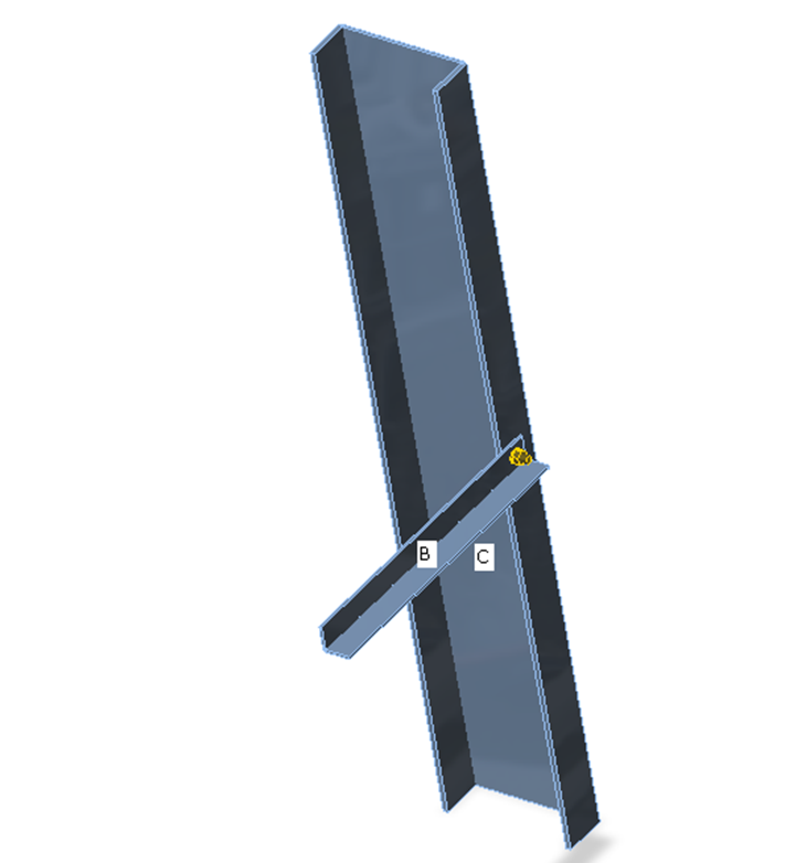
The analyzed FEM model is generated automatically. The designer does not create the FEM model, he creates the joint using manufacturing operations – see the figure.
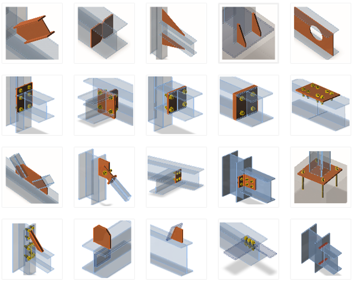
Manufacturing operations/items which can be used to construct the joint
Each manufacturing operation adds new items to the connection – cuts, plates, bolts, welds.
Bearing members and supports
One member of the joint is always set as “bearing”. All other members are “connected”. The bearing member can be chosen by the designer. The bearing member can be “continuous” or “ended” in the joint. “Ended” members are supported on one end, and “continuous” members are supported on both ends.
Connected members can be of several types, according to the load which the member can take:
- Type N-Vy-Vz-Mx-My-Mz – member is able to transfer all 6 components of internal forces
- Type N-Vy-Mz – member is able to transfer only loading in XY plane – internal forces N, Vy, Mz
- Type N-Vz-My – member is able to transfer only loading in XZ plane – internal forces N, Vz, My
- Type N-Vy-Vz – member is able to transfer only normal force N and shear forces Vy and Vz
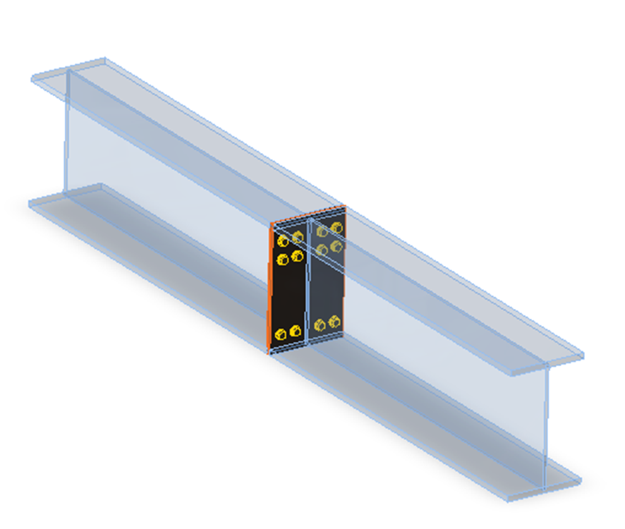
Plate to plate connection transfers all components of internal forces
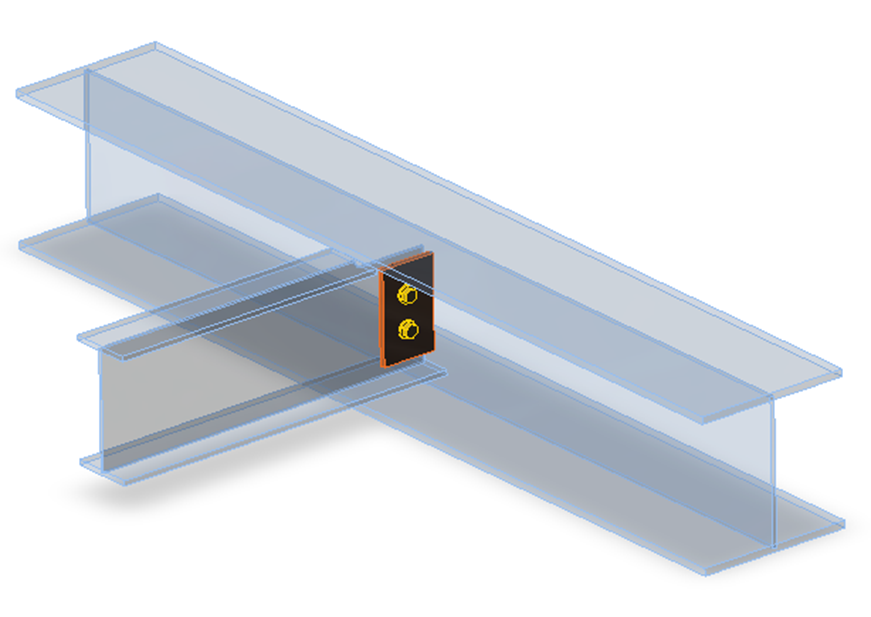
Fin plate connection can transfer only loads in XZ plane – internal forces N, Vz, My
Gusset connection – connection of truss member can transfer only axial force N and shear forces Vy and Vz
Each joint is in the state of equilibrium during the analysis of the frame structure. If the end forces of the individual members are applied to detailed CBFEM model, the state of equilibrium is met too. Thus, it would not be necessary to define supports in the analysis model. However, for practical reasons, the support resisting all translations is defined in the first end of the bearing member. It does influence neither the state of stress nor the internal forces in the joint, only the presentation of deformations.
Appropriate support types respecting the type of the individual members are defined at the ends of the connected members to prevent the occurrence of unstable mechanisms.
The default length of each member is twice its height. The length of a member should be at least 1× the height of the member after the last manufacturing operation (weld, opening, stiffener etc.) due to the correct deformations after the rigid links connecting the cut end of a member to the connection node.