Progettazione strutturale di un giunto 3D generale (AISC)
1 Nuovo progetto
Inizia avviando IDEA StatiCa Connection. Crea un nuovo progetto selezionando il modello iniziale più vicino al progetto desiderato, inserendo il nome e scegliendo il codice di progetto AISC e i gradi di acciaio predefiniti come mostrato di seguito.
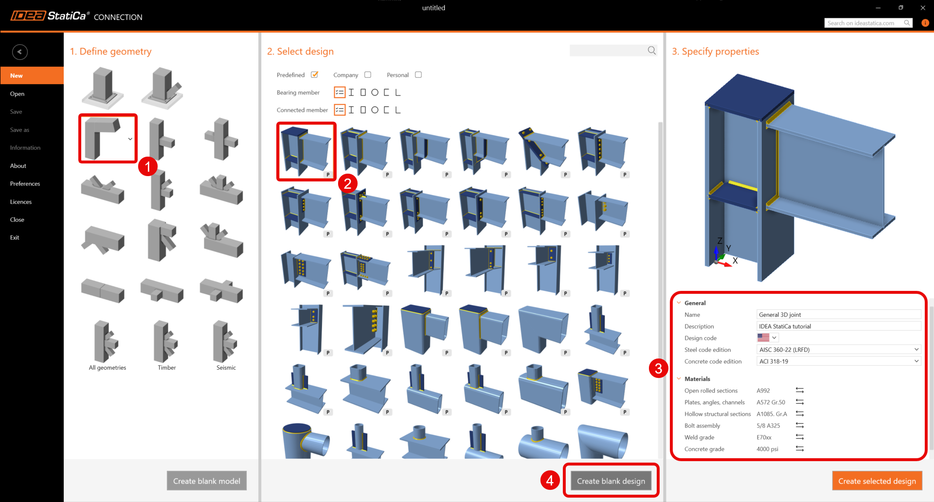
Poiché si lavora con il codice AISC, impostare le unità imperiali (vedere Come cambiare il sistema di unità).
2 Geometria
Due travi sono state aggiunte automaticamente come parte del modello di progetto vuoto.
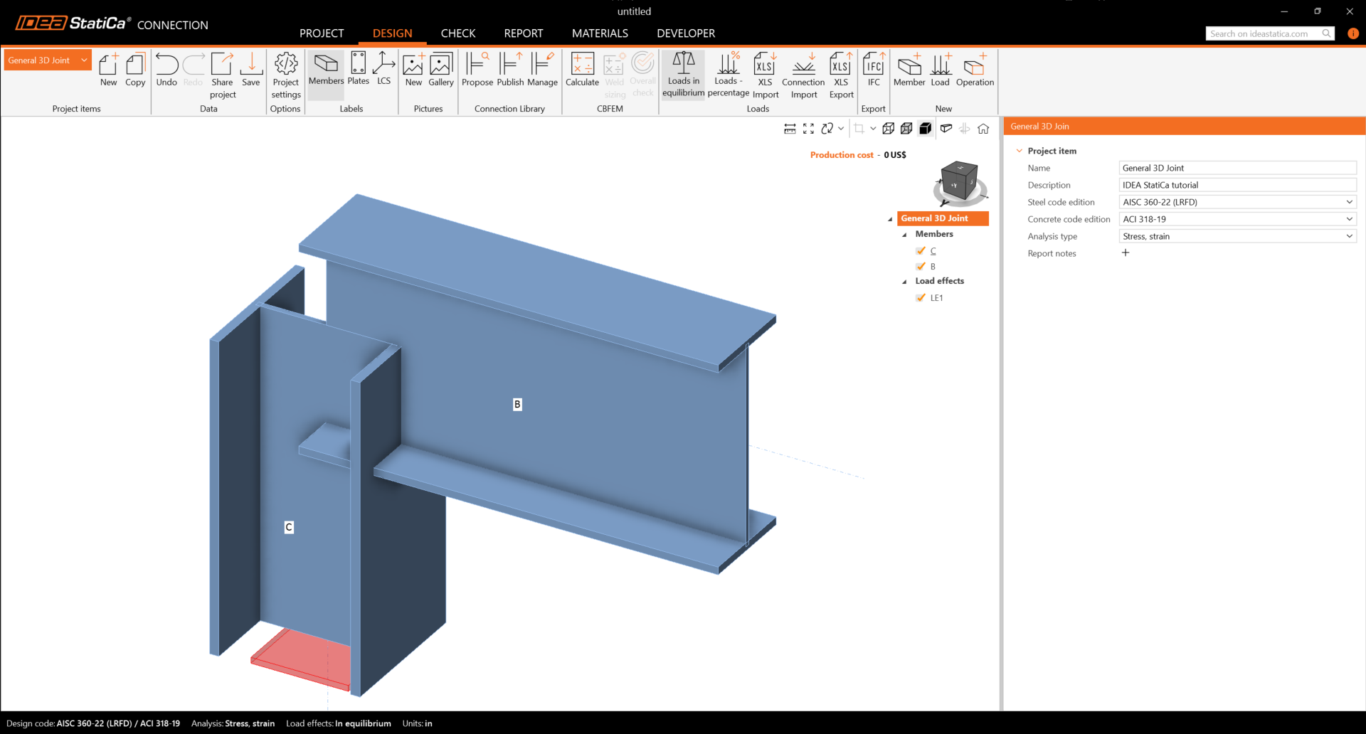
Elemento C
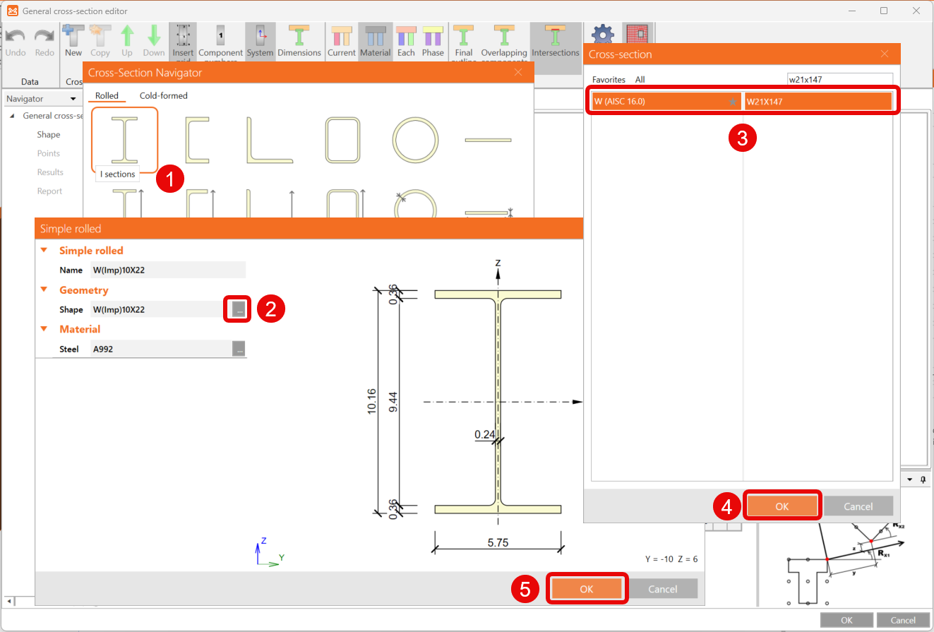
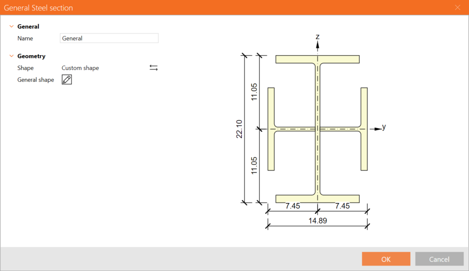
Verrà creata una sezione trasversale generale per l'elemento colonna. Per farlo, selezionare la scheda Saldata, Composta e fare clic su Sezione trasversale in acciaio generale.
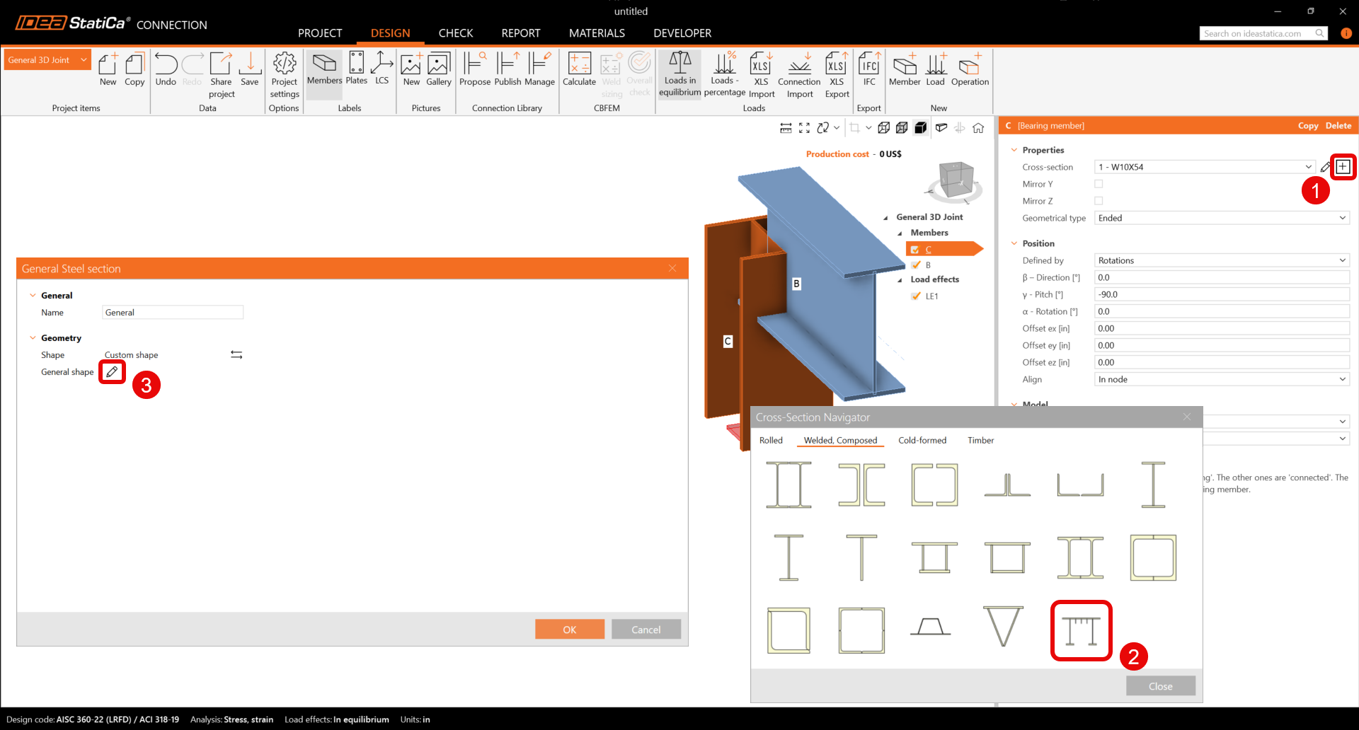
L'editor della sezione trasversale generale viene aperto ed è possibile iniziare a comporre la sezione trasversale selezionando le sezioni a I nel Navigatore sezioni trasversali.
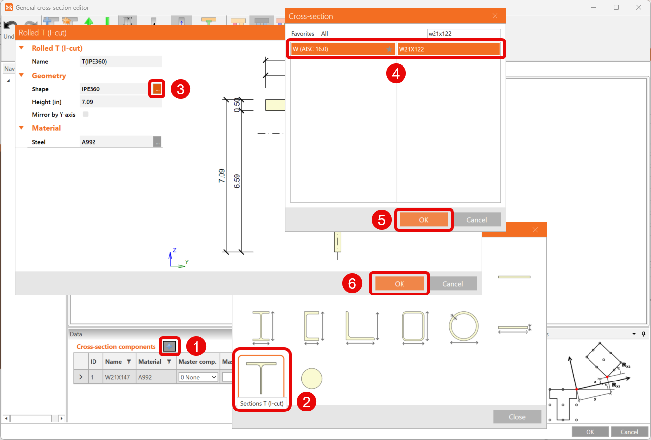
Continuare facendo clic sull'icona Aggiungi nuova entità e selezionando le Sezioni T (taglio a I). Si apre la finestra T laminato (taglio a I) e sarà possibile modificare la forma.
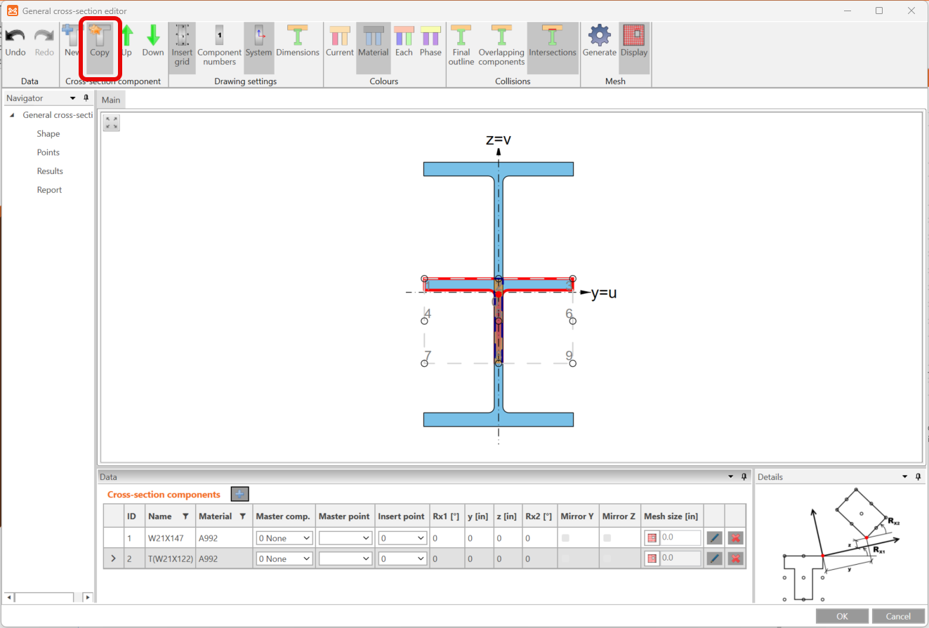
Eseguire una copia di questa entità facendo clic sull'icona Copia nella barra multifunzione superiore.
Successivamente, spostare e ruotare le entità a forma di T aggiunte per progettare l'intera sezione trasversale modificando i valori nella scheda Componenti della sezione trasversale come nella figura seguente.
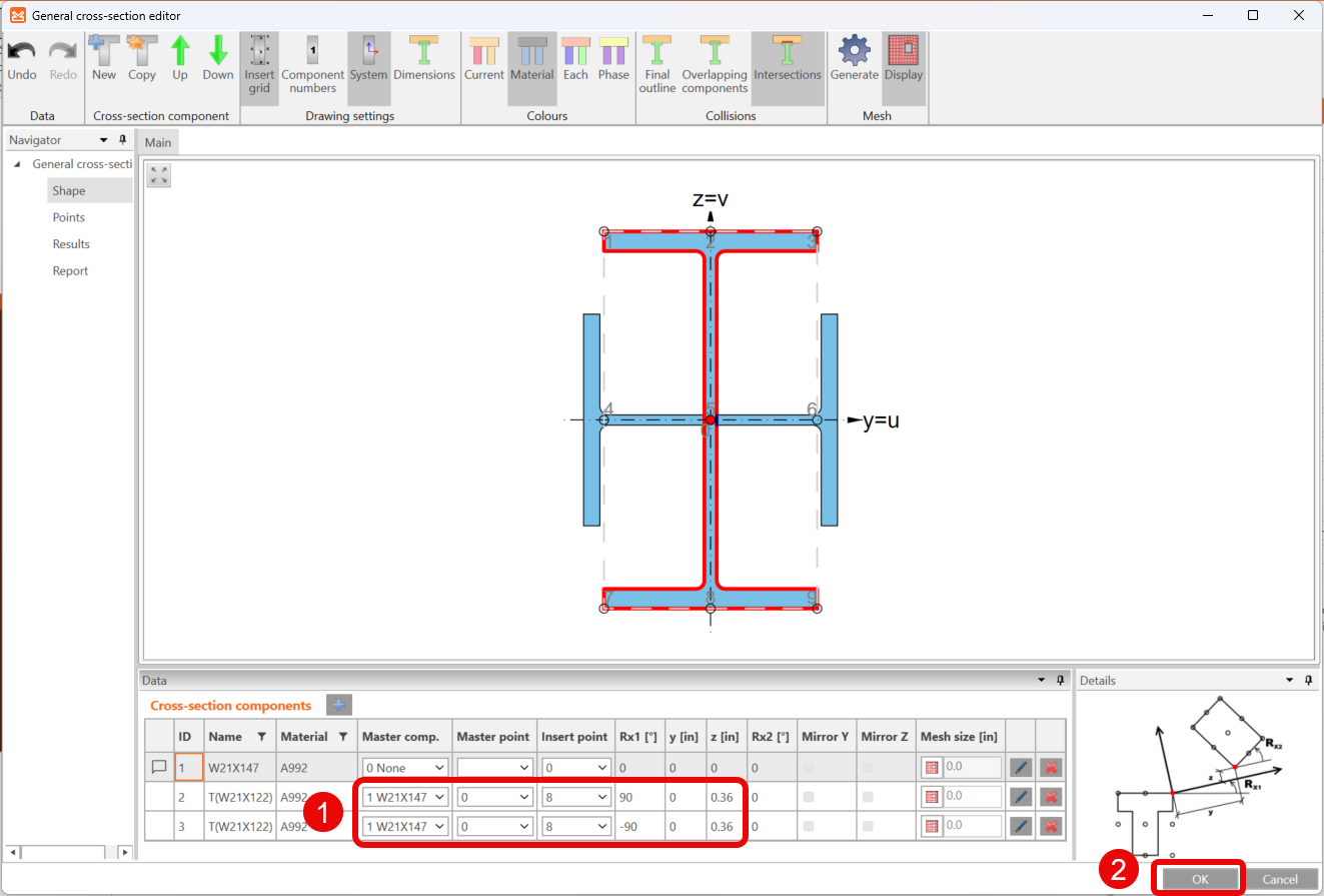
Ora si dispone del progetto finale della sezione trasversale per l'elemento SL.
Per ulteriori informazioni, vedere Come creare e utilizzare una sezione trasversale personalizzata.
Elemento B
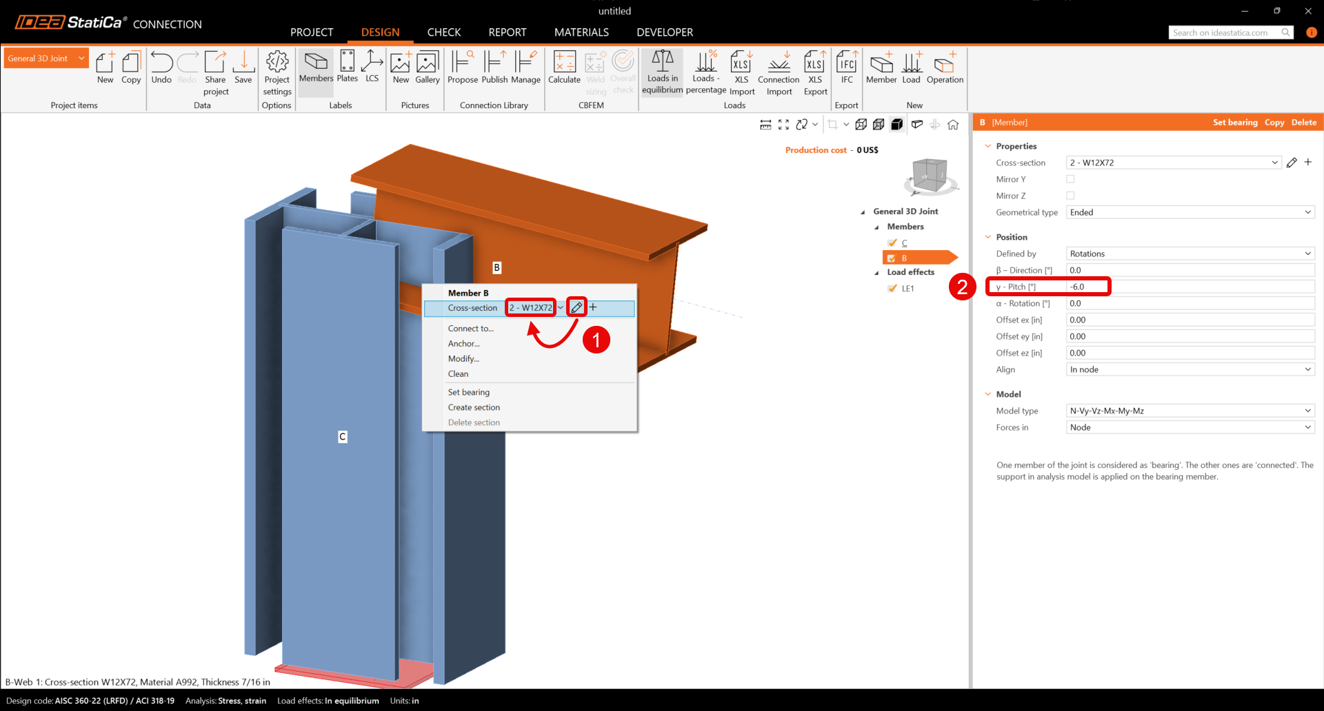
Iniziare con il clic destro sulla trave B e impostare la sezione trasversale su 12X72 dalla libreria W (AISC 16.0).
Sarà inoltre necessario modificare le proprietà dell'elemento B.
Elemento M3
Nella barra multifunzione superiore, selezionare l'icona Elemento per aggiungere il nuovo elemento M3. Impostare la sezione trasversale su W8X21 dalla libreria W (AISC 16.0) sulla trave M3.
È possibile procedere e modificare le proprietà dell'elemento M3.
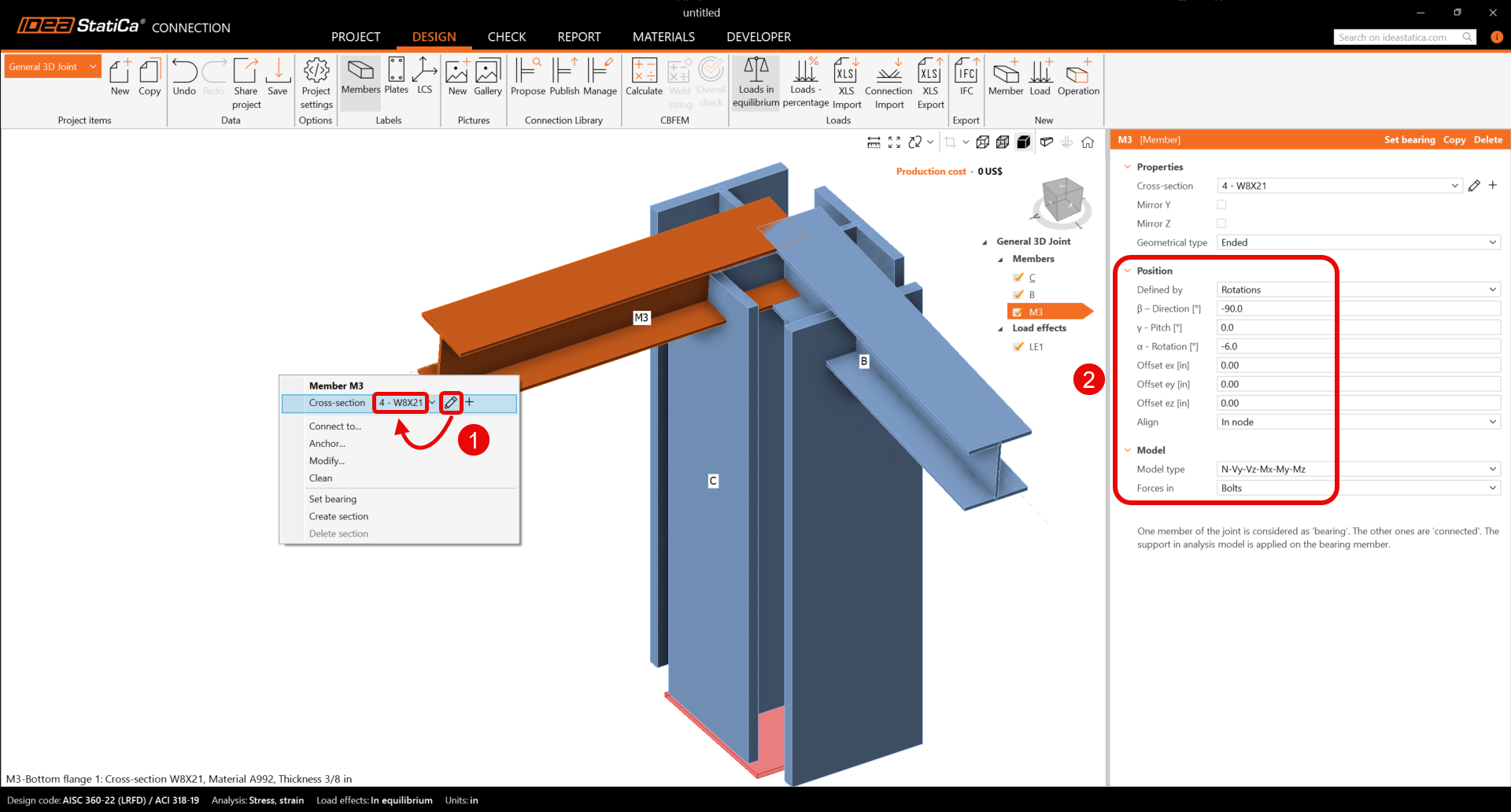
Per ulteriori informazioni sulla proprietà Forze, vedere Come definire la posizione del carico.
Elemento M4
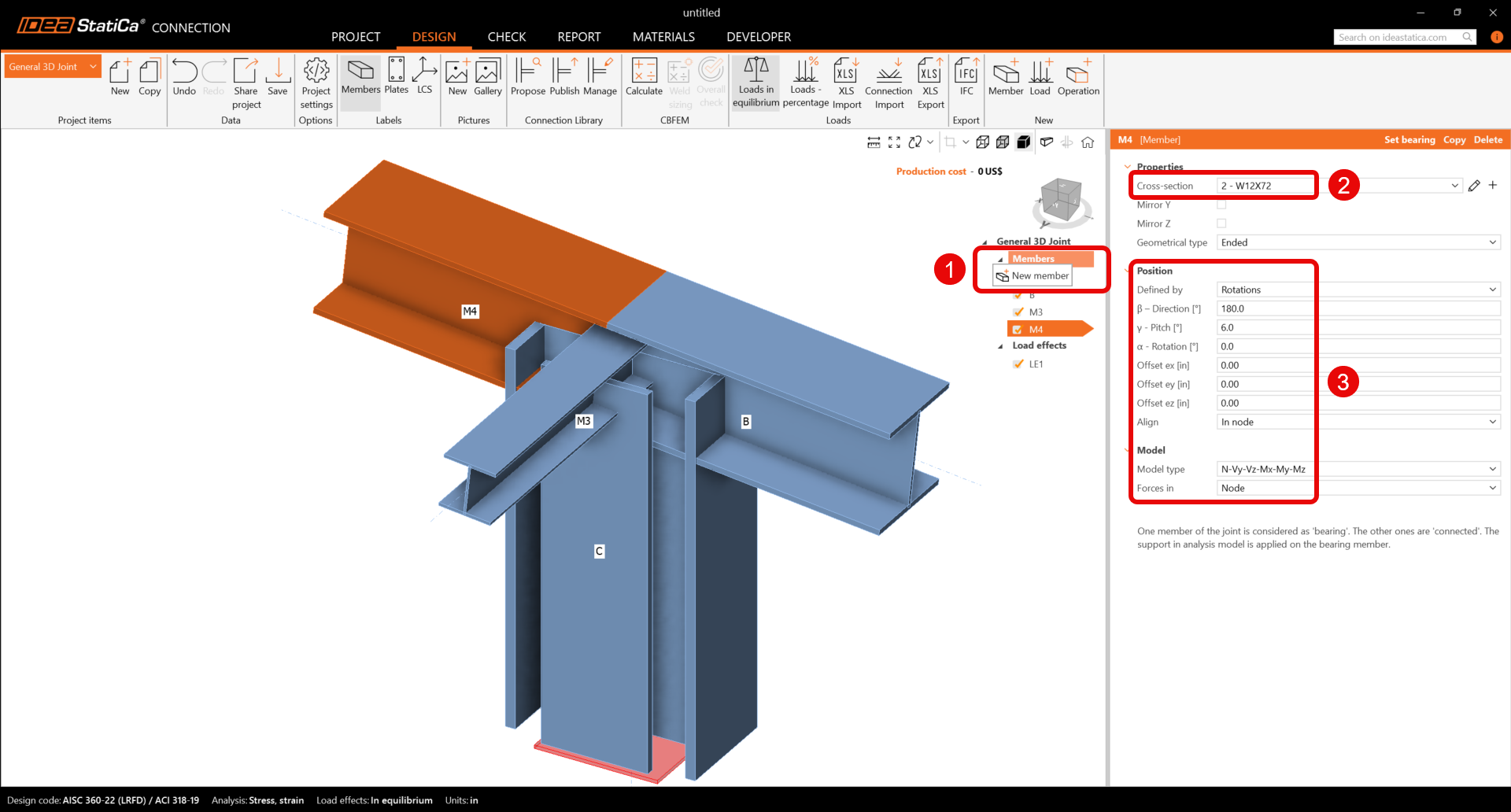
Fare clic con il tasto destro del mouse sulla riga Elementi nell'albero delle entità nella scena 3D. Scegliere il comando Nuovo elemento dal menu contestuale. Continuare e modificare le proprietà dell'elemento M4.
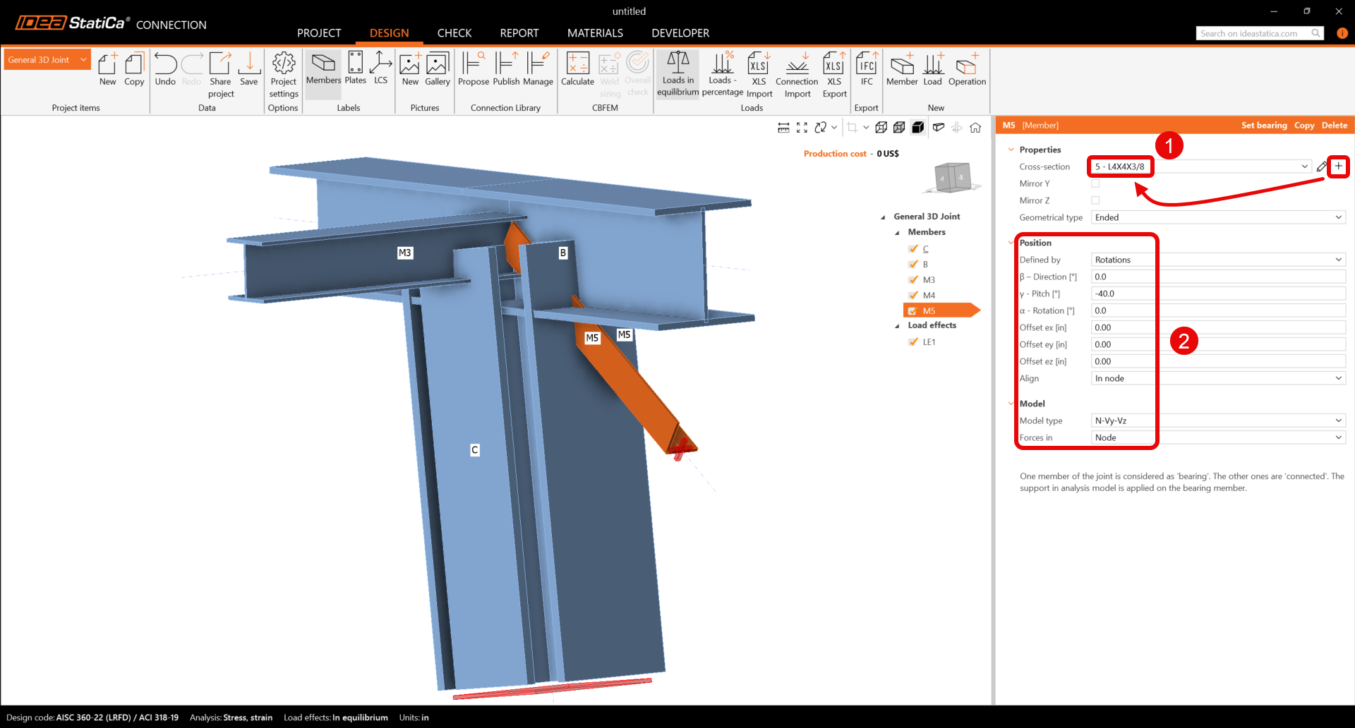
Elemento M5
Aggiungere un altro elemento, impostare la sua sezione trasversale su L4X4X3/8 dalla libreria L (AISC 16.0) e aggiornare le proprietà.
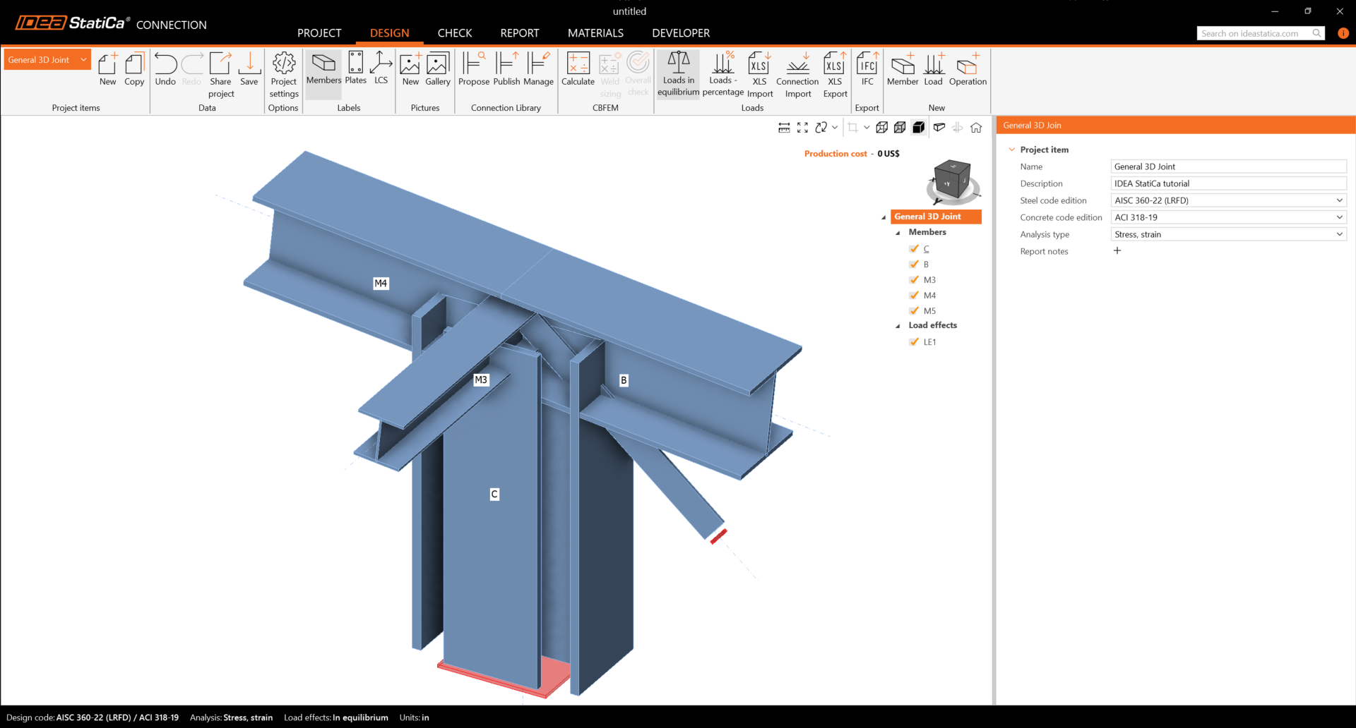
Verificare la geometria finale degli elementi.
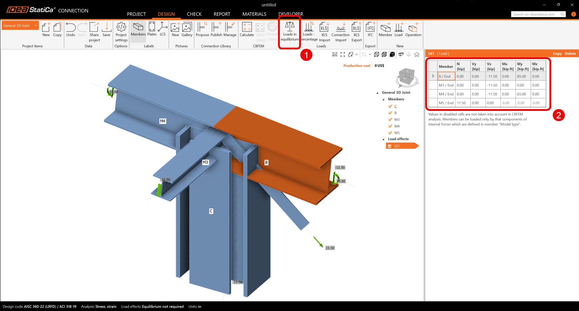
3 Effetti del carico
Un effetto del carico è stato aggiunto automaticamente. Inserire i valori delle forze interne nel grafico e disattivare Carichi in equilibrio. È possibile aggiungere ulteriori casi di carico.
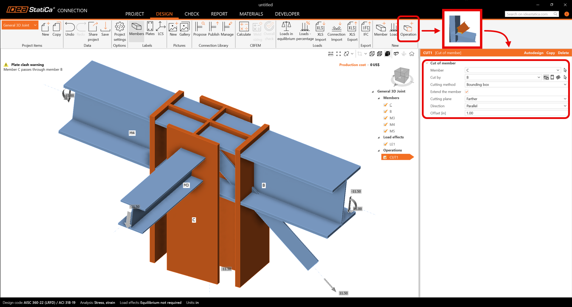
4 Progettazione
Aggiungerne una nuova tramite il comando nuova Operazione nella barra multifunzione superiore. Prima, selezionare l'operazione Taglio dell'elemento per estendere la colonna. Ora modificare le proprietà dell'operazione CUT1. Seguire la figura seguente.
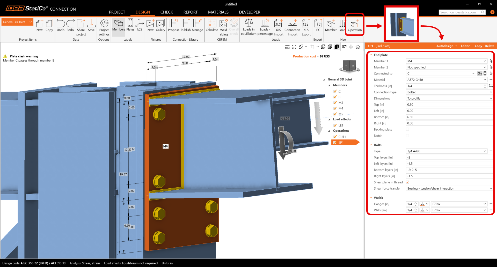
Continuare e aggiungere la successiva Operazione di produzione. Ora selezionare la Piastra d'estremità e modificare le proprietà dell'operazione EP1.
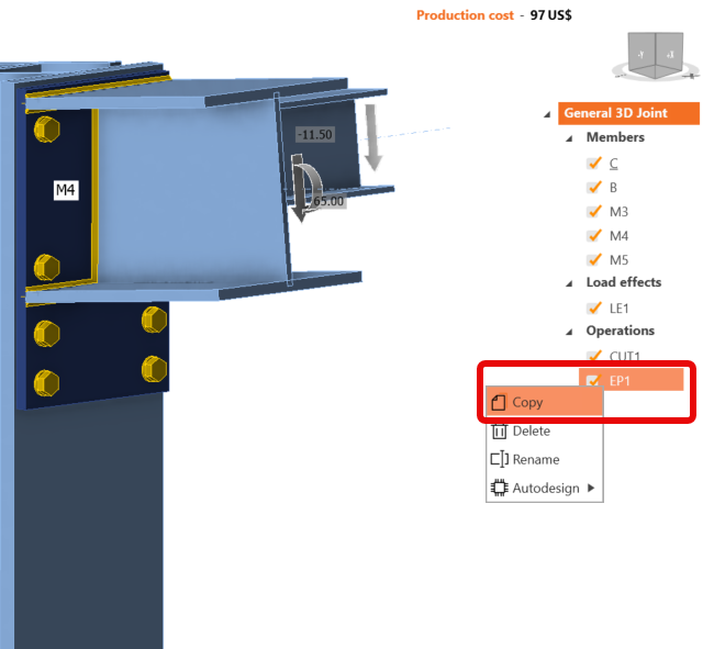
Copiare l'operazione EP1. Con il tasto destro del mouse, fare clic su EP1 e scegliere Copia.
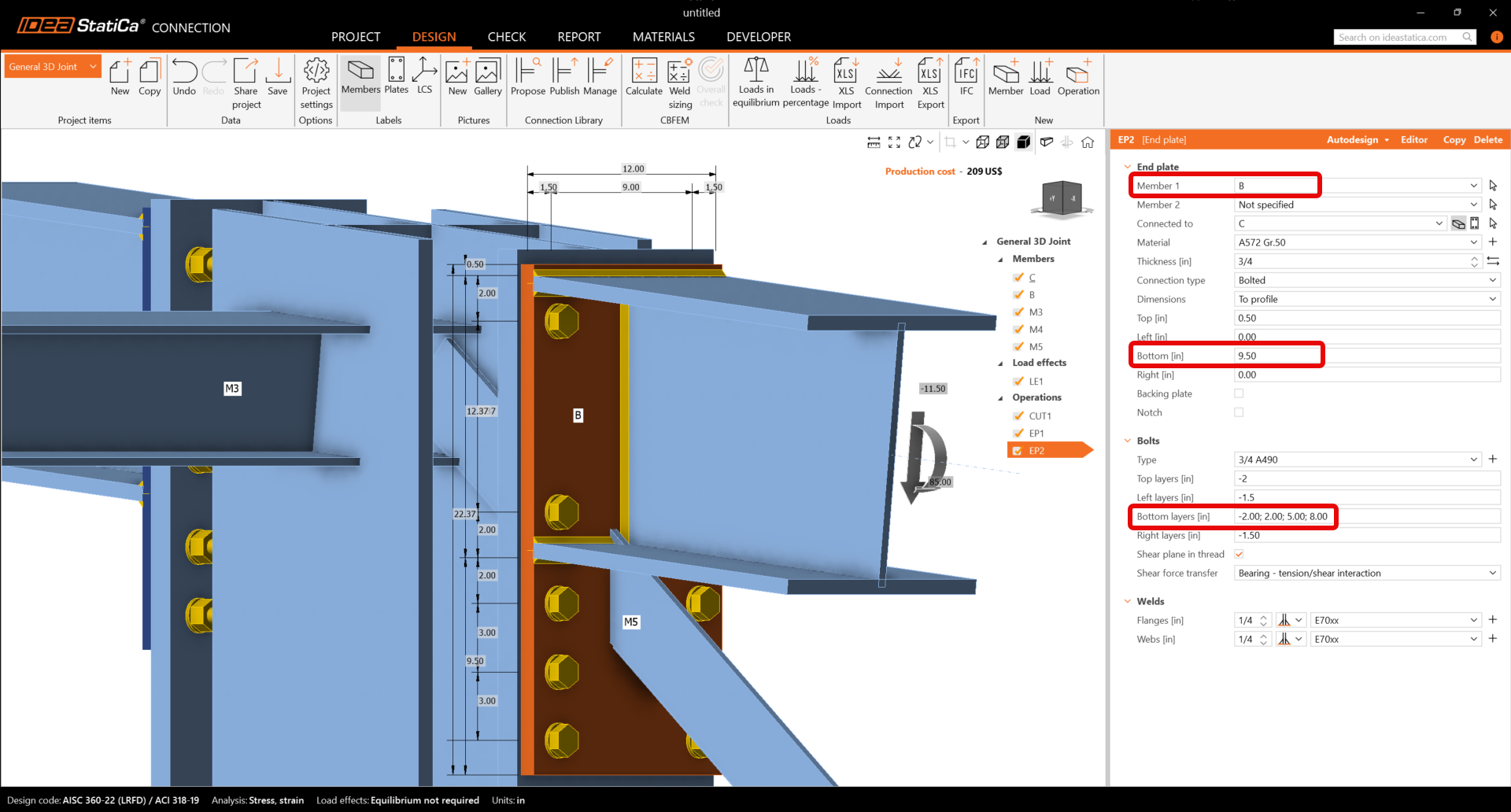
Ora è necessario impostare le proprietà corrette di EP2.
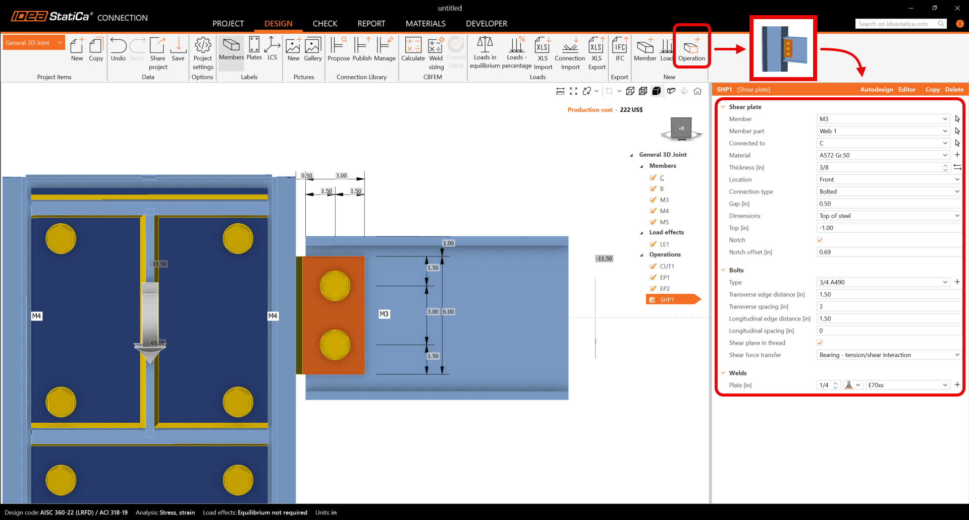
Continuare e inserire una Piastra d'anima e modificare le proprietà dell'operazione SHP1. Seguire la figura seguente.
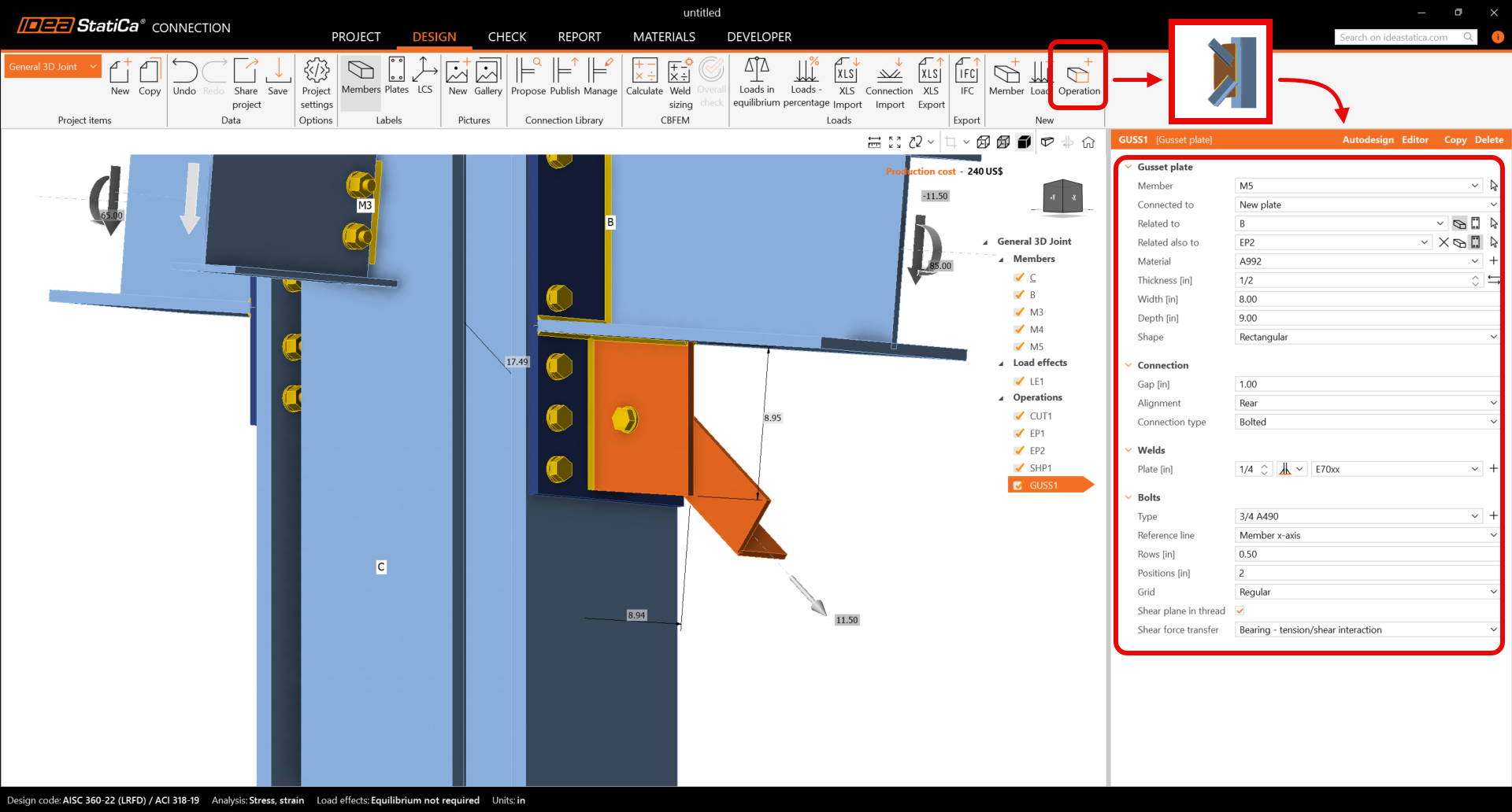
Completare la progettazione aggiungendo un'operazione Piastra di nodo e impostare i parametri per GUSS1.
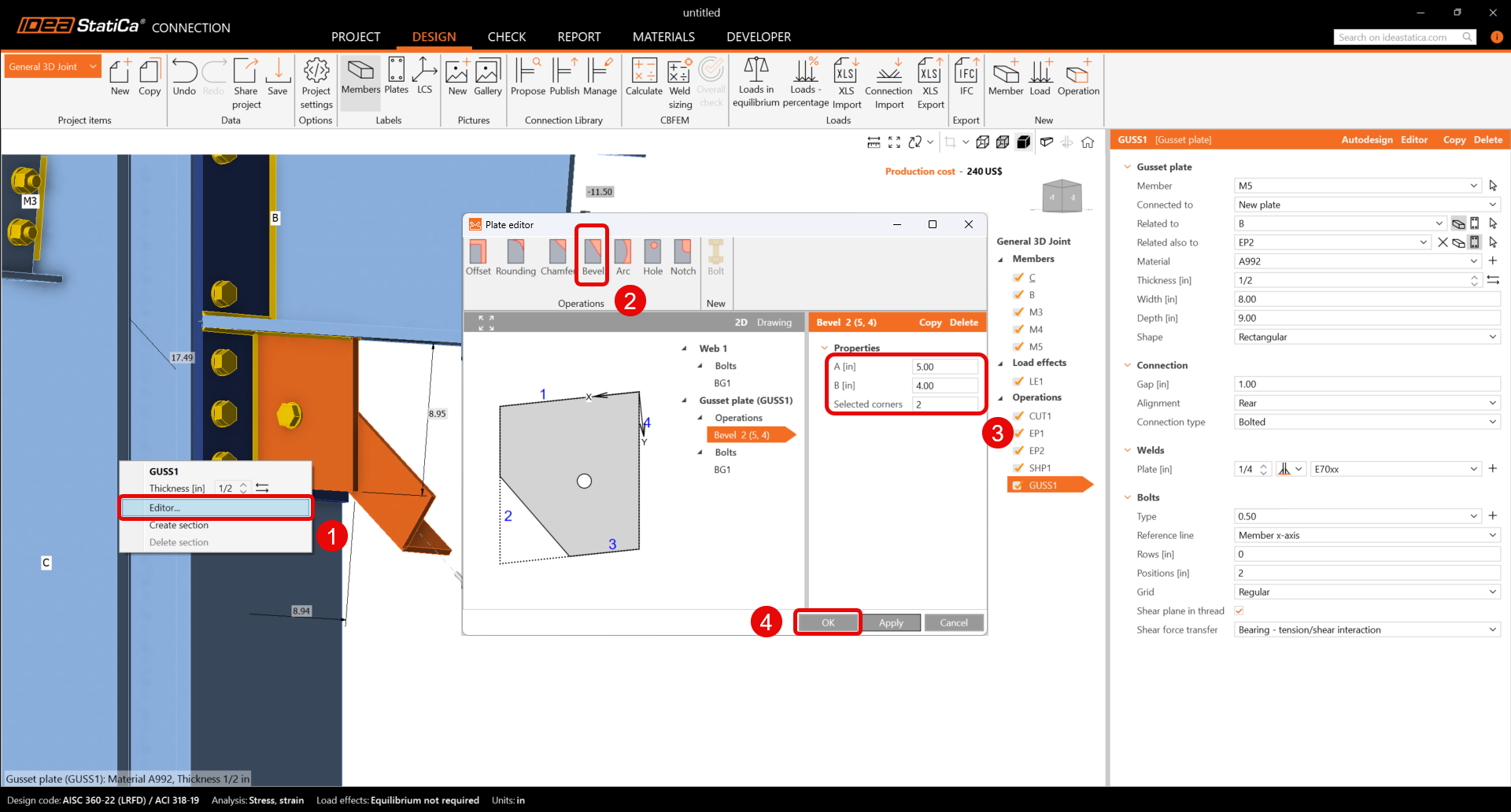
Infine, modificare la forma della piastra di nodo. Con il tasto destro del mouse fare clic sulla piastra GUSS1 nella scena 3D e scegliere Editor. All'interno dell'editor della piastra, modificare la piastra di nodo tramite l'inserimento di un Bisello.
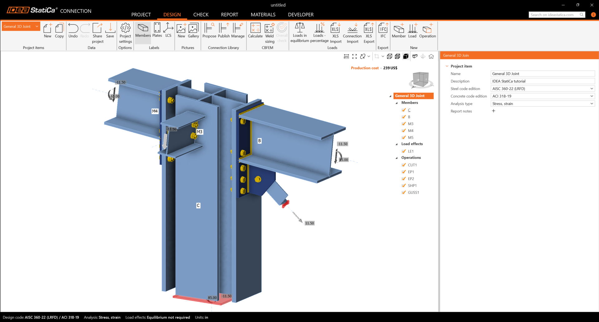
Verificare il progetto finale del giunto.
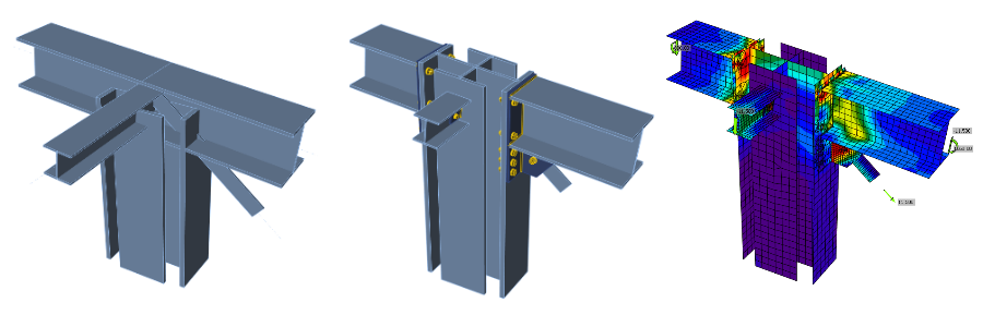
5 Calcolo e verifica
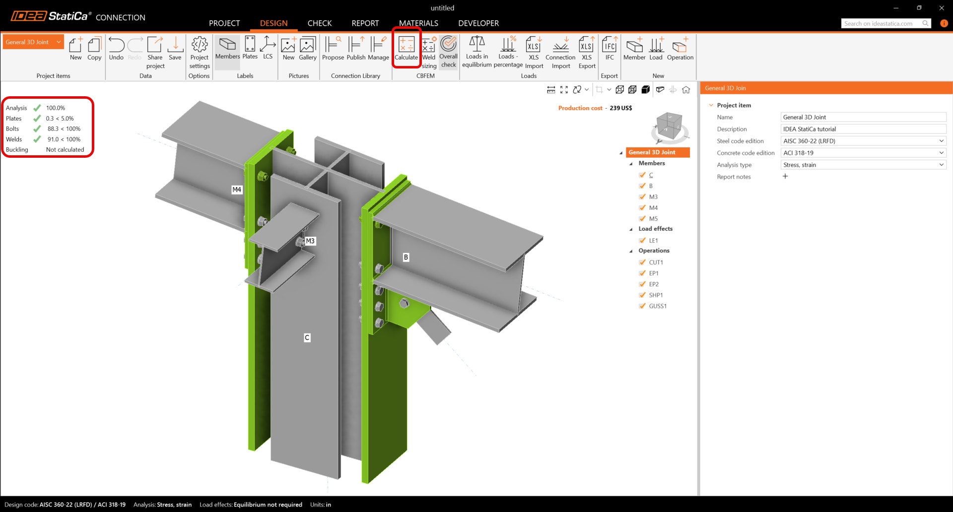
È possibile avviare l'analisi facendo clic su Calcola nella barra multifunzione. Il modello di analisi viene generato automaticamente, il calcolo viene eseguito e sarà possibile visualizzare la verifica complessiva insieme ai valori di base dei risultati della verifica.
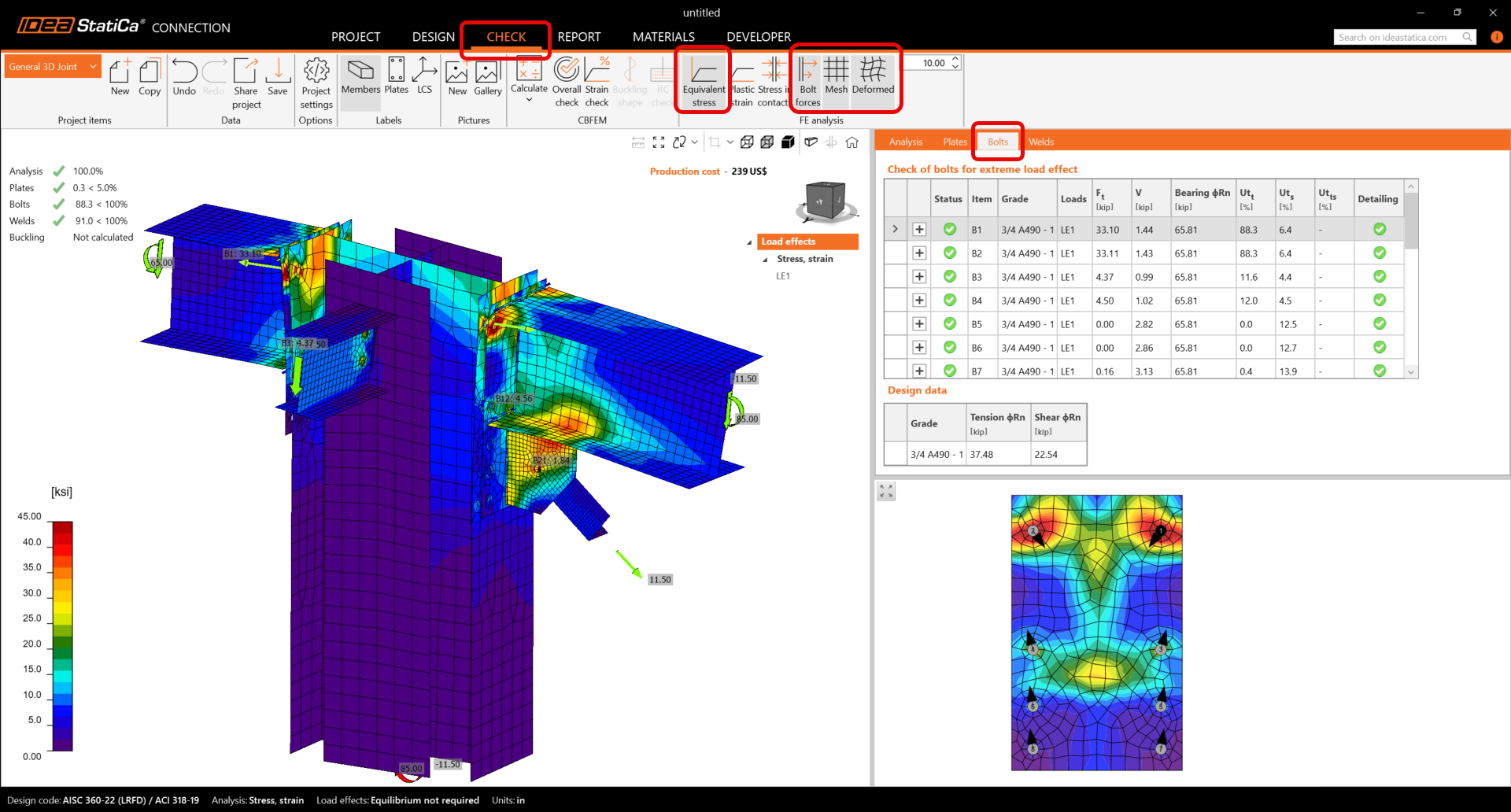
Andare alla scheda di visualizzazione Verifica e attivare Tensione equivalente, Forze sui bulloni, Rete e Deformata dalla barra multifunzione per ottenere un quadro completo di ciò che accade nel giunto.
I valori delle verifiche e delle forze sui bulloni insieme alle equazioni di verifica sono visualizzati nella tabella Bulloni; analogamente, è presente una scheda per le saldature, ecc.
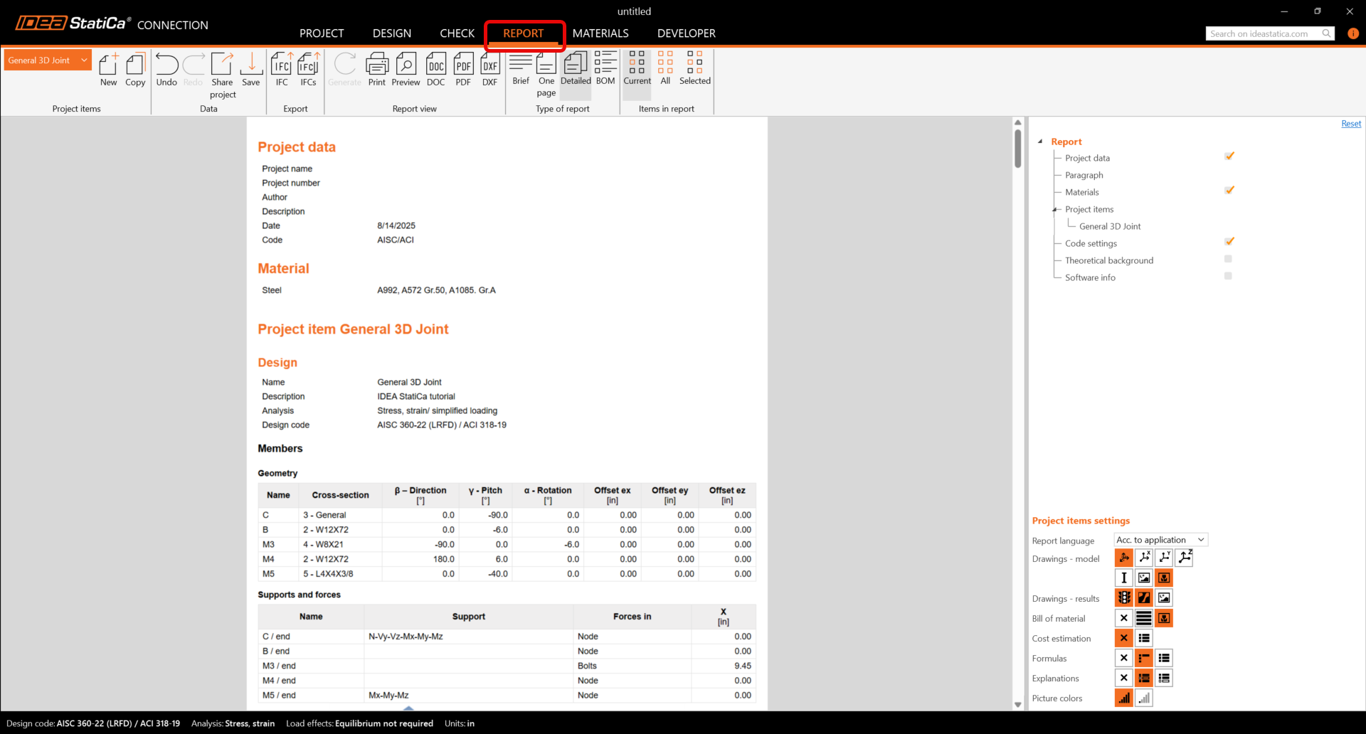
6 Relazione
Infine, andare alla scheda Relazione. IDEA StatiCa offre una relazione completamente personalizzabile da stampare o salvare in formato modificabile.
Hai progettato, ottimizzato e verificato normativamente un giunto 3D generale secondo AISC.