Sensibilità della rete in IDEA StatiCa Connection
Esistono alcuni criteri per la generazione della rete nel modello di collegamento. La verifica normativa del collegamento deve essere indipendente dalla dimensione degli elementi. La generazione della rete su una piastra singola non presenta problemi. Occorre prestare attenzione a geometrie complesse come pannelli irrigiditi, T-stub e piastre di base. Per geometrie complicate è necessario eseguire un'analisi di sensibilità relativa alla discretizzazione della rete.
In IDEA StatiCa Connection, tutte le piastre della sezione trasversale di un elemento hanno una suddivisione comune in elementi. La dimensione degli elementi finiti generati è limitata. La dimensione minima degli elementi è impostata a 10 mm e la dimensione massima a 50 mm (modificabile nelle impostazioni del codice). Le reti su ali e anime sono indipendenti tra loro. Il numero predefinito di elementi finiti è impostato a 8 elementi per l'altezza della sezione trasversale, come mostrato nella figura seguente. L'utente può modificare i valori predefiniti nelle impostazioni del codice. La rete delle piastre d'estremità è separata e indipendente dalle altre parti del collegamento. La dimensione predefinita degli elementi finiti è impostata a 16 elementi per l'altezza della sezione trasversale.

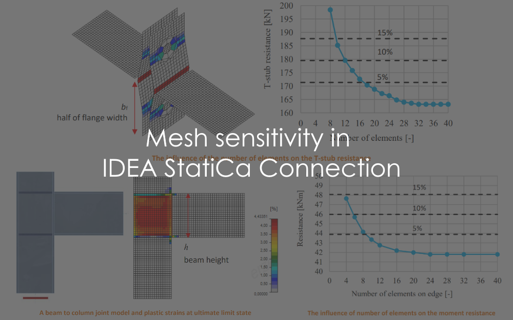
Il seguente esempio di un giunto trave-colonna mostra l'influenza della dimensione della rete sulla resistenza a momento. Una trave a sezione aperta IPE220 è collegata a una colonna a sezione aperta HEA200 e caricata da un momento flettente, come mostrato nella figura seguente. Il componente critico è il pannello d'anima della colonna a taglio. Il numero di elementi finiti lungo l'altezza della sezione trasversale varia da 4 a 40 e i risultati vengono confrontati. Le linee tratteggiate rappresentano le differenze del 5%, 10% e 15%. Si raccomanda di suddividere l'altezza della sezione trasversale in 8 elementi.
Viene presentato uno studio di sensibilità della rete per un T-stub in trazione. La metà della larghezza dell'ala è suddivisa in 8-40 elementi e la dimensione minima degli elementi è impostata a 1 mm. L'influenza del numero di elementi sulla resistenza del T-stub è mostrata nella figura seguente. Le linee tratteggiate rappresentano le differenze del 5%, 10% e 15%. Si raccomanda di utilizzare 16 elementi sulla metà della larghezza dell'ala.
Per ulteriori dettagli, consultare il nostro Background Teorico.