The teams consisted of structural engineers from engineering firms and steel fabricators, and each was guided by an experienced connection designer. After the groups presented their designs, we from IDEA StatiCa had the opportunity to model the connections with the Connection application. That way, we were able to analyze the results immediately and discuss them together.
We explain the designs and results in more detail below. The article is divided into two parts, one for each steel connection design challenge.
1 - Design a complex column-beam connection with edge beams
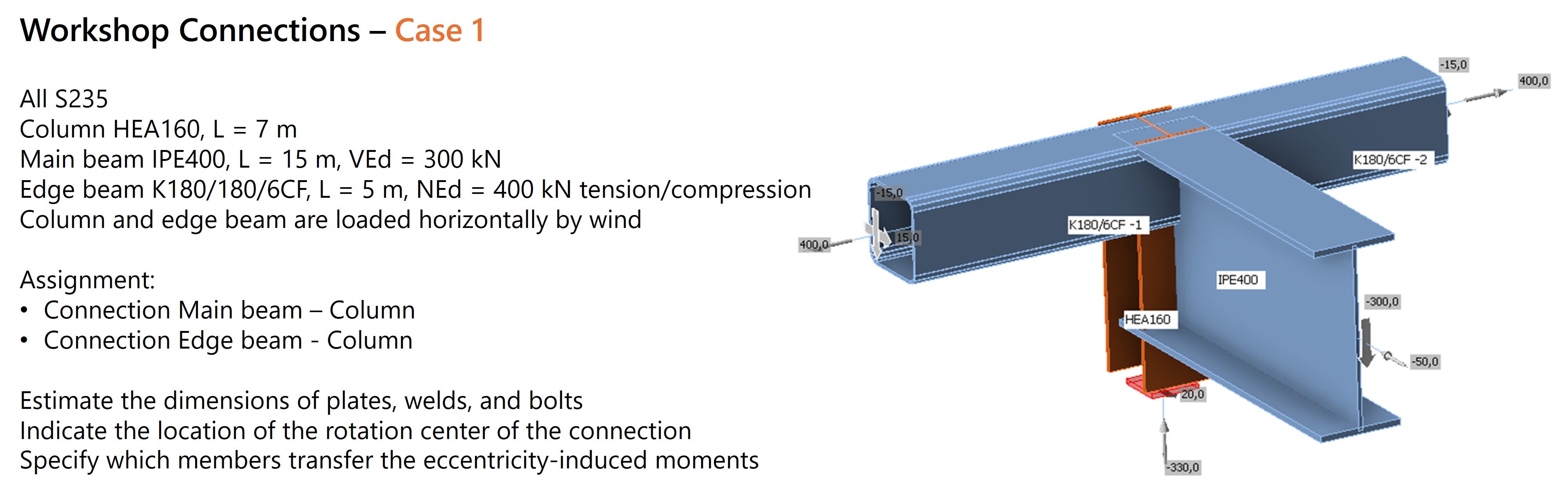
In the first design challenge, we focused on a joint connecting four members. The internal forces and profiles made this a challenging design task, as shown by the variety of solutions: each of the six teams took a different approach. This is exactly what makes this profession so fascinating: there is never one right solution.
The biggest challenge arose with the connection of the edge beams. Two rectangular hollow sections (180/180/6) had to be connected to a column (HEA160) or main beam (IPE400). Combined with the imposed loads, this created a difficult design situation.
Below is an overview of the connections, sketches and models worked out in the steel connection software IDEA StatiCa. We then discuss each connection and highlight key insights from the discussions and results.
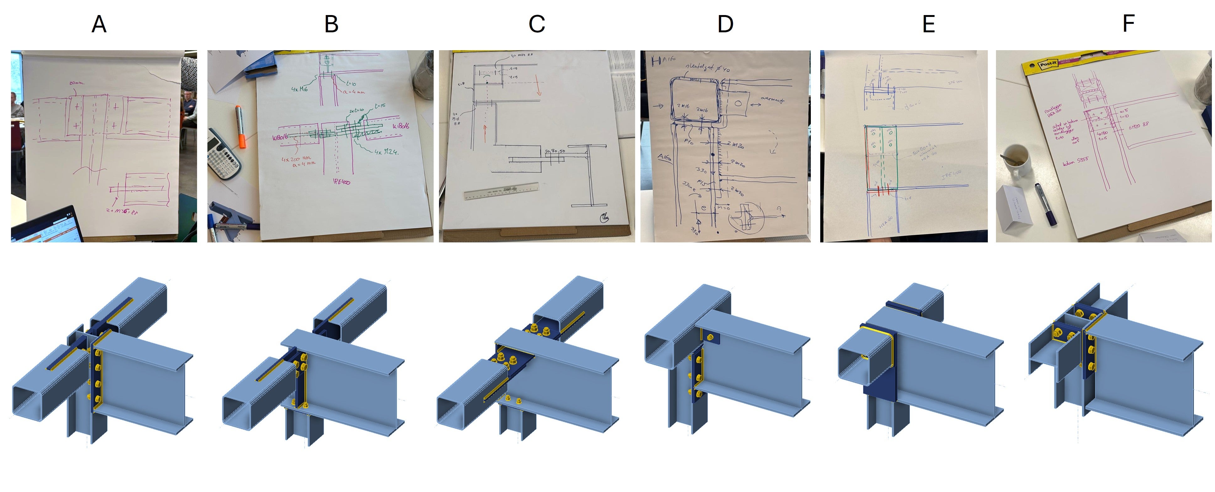
Group A
Group A chose to extend the column and connect the girder beam (IPE400) with an endplate. The challenge was mainly in connecting the RHS edge beams to the HEA160 column. For this, a gusset plate connection with two M36 bolts was proposed. When modeling in IDEA StatiCa, however, it quickly became apparent that there was insufficient space for this bolt size. As the experts during the workshop emphasized, it is essential to draw to scale to understand the manufacturability of a connection.
Instead of a direct welded connection, the group chose to extend the connecting plate through a slot in the column web to better transfer forces and reduce stresses in the column web.
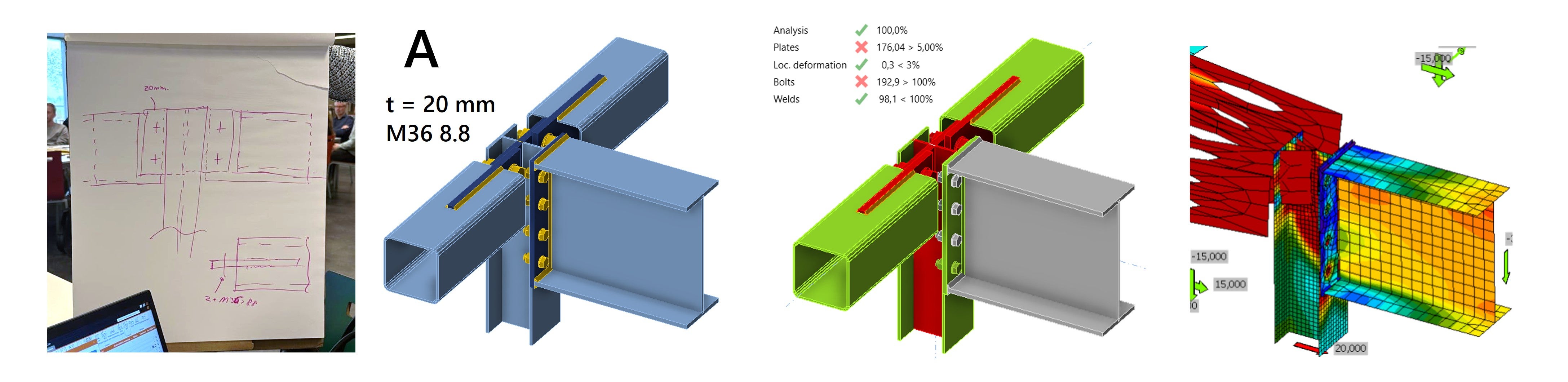
When calculating the connection in IDEA StatiCa, large plastic strains arise in the connection of the edge beams. Due to the high axial compressive force of 400 kN in the edge beams and an eccentricity in the gusset plate, a bending moment occurs in the connection. Using a finite element analysis tool like IDEA StatiCa, this quickly becomes visible through the deformations that occur.
By increasing the plate thicknesses, the connection can meet the requirements. With a continuous 35 mm plate and 2x M33 8.8 bolts, sufficient strength and rigidity is achieved.
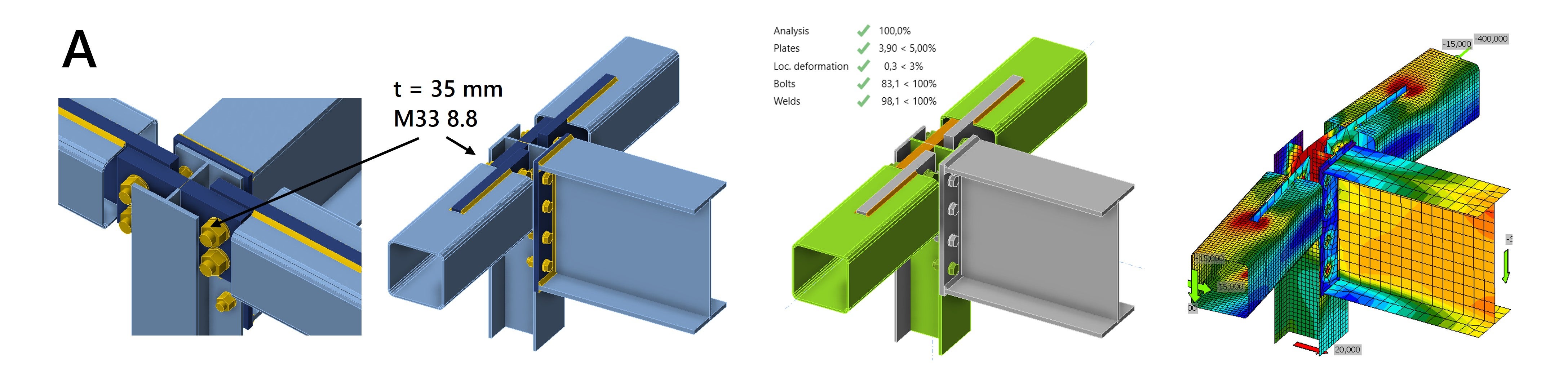
Although the solution is satisfactory, avoiding the eccentricity is worth considering and probably more structurally efficient.
Group B
Group B had a similar connection, but here the main beam was extended. Choosing a symmetrical connection of the square hollow section (SHS) beams avoids the additional bending moment. With the prescribed plate thicknesses, the plastic strain is just under 5% limit.
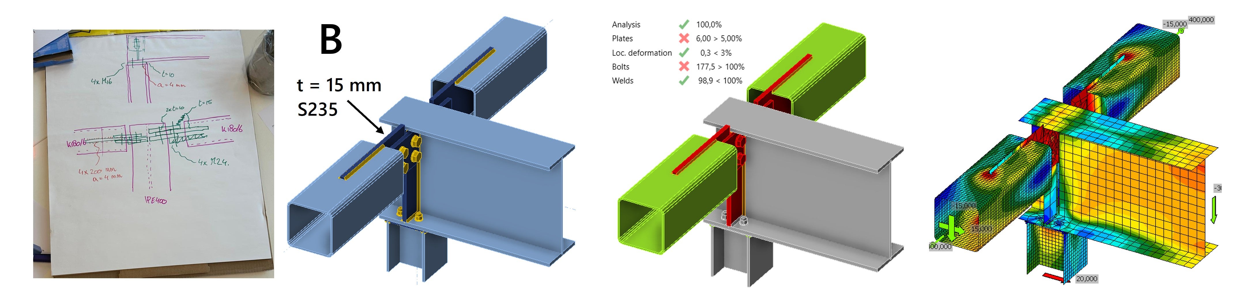
By thickening the plates and providing sufficient welds, the combination of axial compression and horizontal shear can be resisted, keeping the plastic strain below 5%.
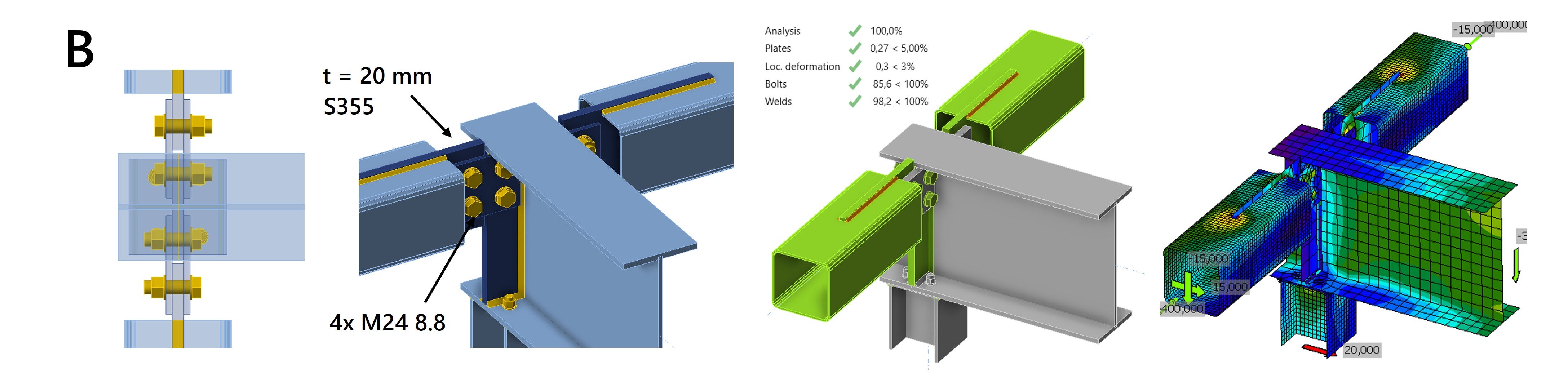
Only the bolts are still not satisfactory when using 4x M24 8.8. However, simply reinforcing the bolts does not solve the problem because the code-check is limited by the bearing resistance. An alternative solution is to increase the steel grade of the connection plates to S355. This allows optimal results to be achieved with only minimal increases in plate thickness and bolt size.
Group C
Group C has a similar connection, but unlike groups A and B, it is more suitable for horizontal loading because the gusset plate is rotated a quarter turn. We are again dealing with an eccentricity and encounter the same problems as in Group A. The use of four bolts instead of two makes the joint stiffer, but we still see high plastic strain and deformation. Welding the gusset plate to the stiffener and increasing the plate thicknesses help make the joint stiffer, but eccentricity will always be present.
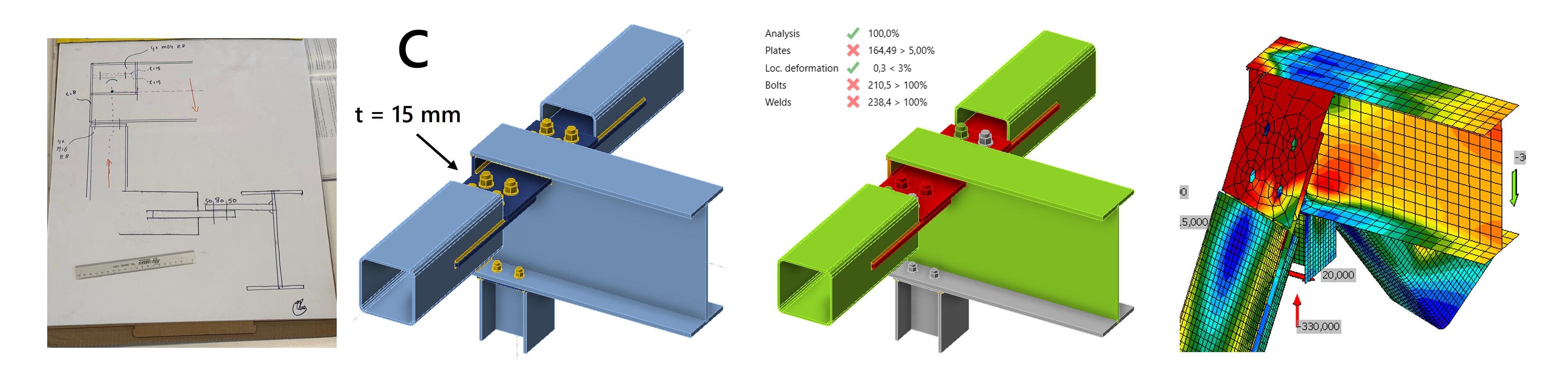
By increasing the plate thicknesses from 15 mm to 30 mm, the joint can meet the design requirements with 4x M24 8.8 bolts.
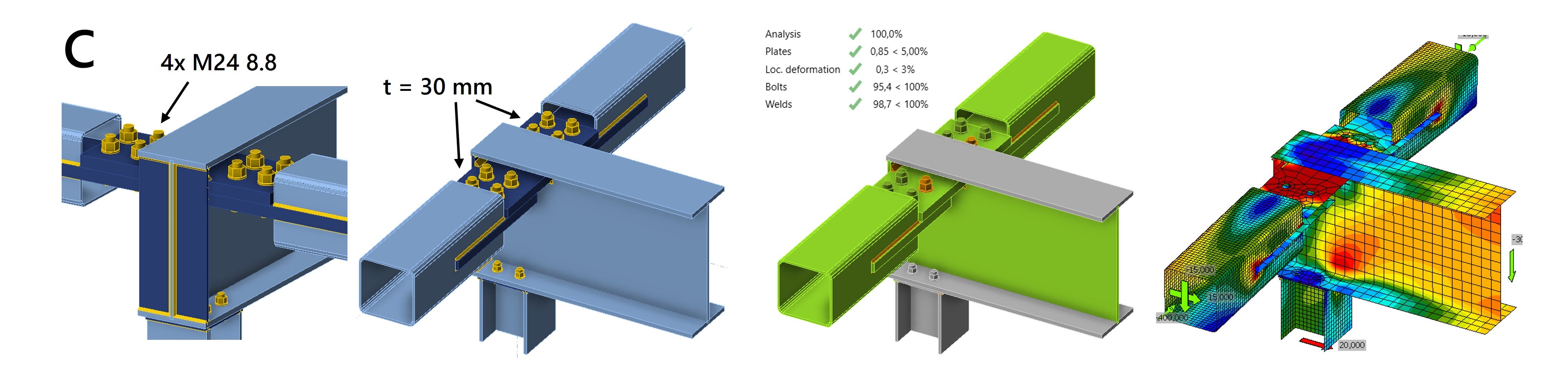
This type of joint functions most safely without eccentricities. If an eccentricity is unavoidable due to practical reasons, the connection will be especially suitable for transferring a transverse force in one direction, in the direction where the connection is stiffest. The combination of an eccentricity with large normal compressive force and a transverse force in the weak direction of the connection will cause the member to bend out and risk buckling.
Buckling analysis
To properly assess this risk, it makes sense to perform an additional buckling analysis. With IDEA StatiCa, a linear buckling analysis can be performed, which shows that for plates with insufficient thickness, a buckling shape resembling global buckling may occur. Based on the corresponding buckling factor, this can be interpreted as a buckling failure.
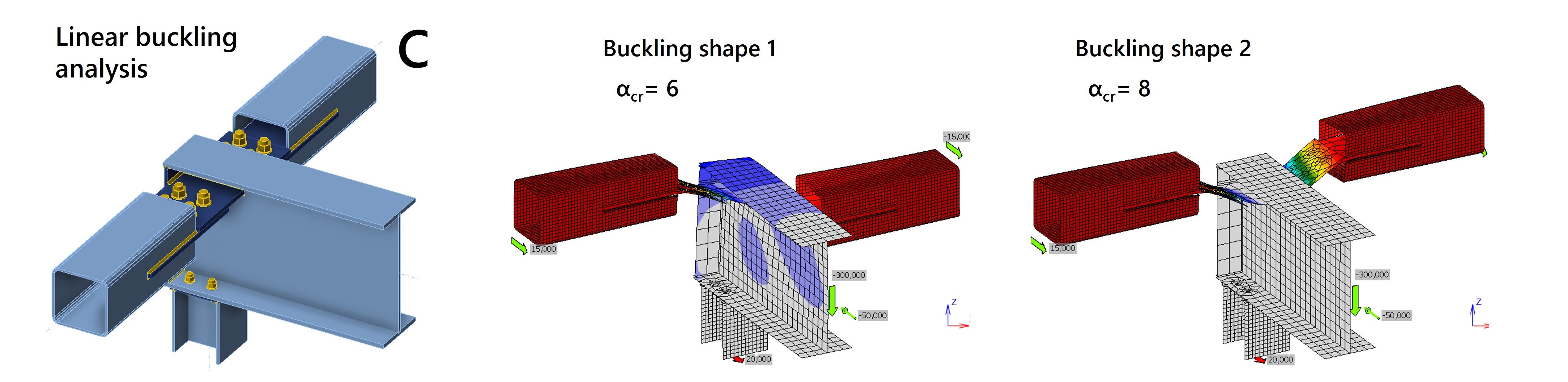
More information about this and how IDEA StatiCa performs linear buckling analysis can be found in the following article Global buckling vs. local buckling. What does it mean?
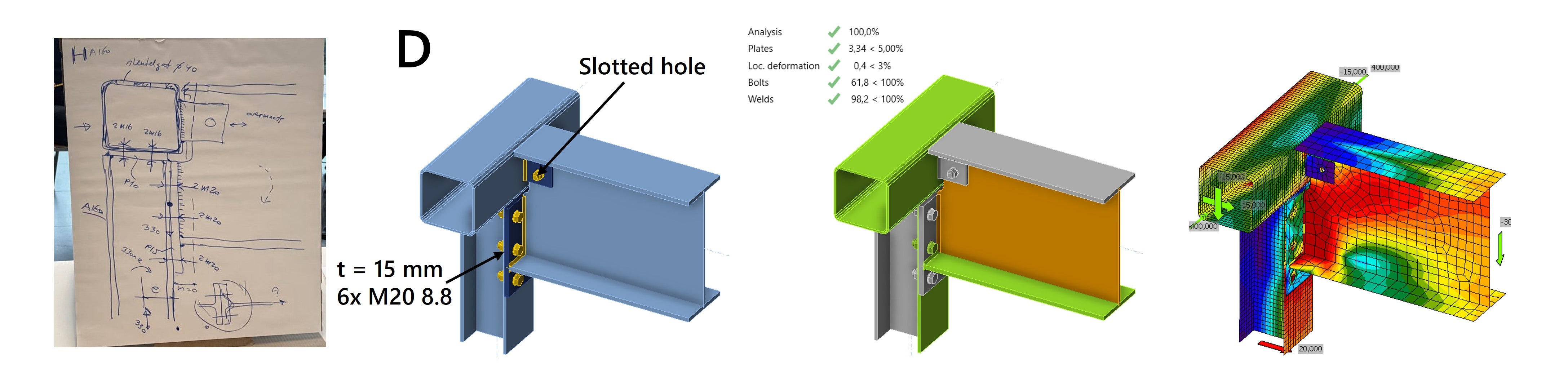
Group D
Group D takes a different approach and the problems seen in the first three groups are directly avoided by continuing the edge beams. The IPE400 is connected to the partially continuous column with an endplate and to the edge beam with a small lip plate. The results show that the connection performs constructively well and the forces are efficiently transmitted.
Since it is a shear connection, the group recommends using a slotted hole in the fin plate to prevent excessive force from being transmitted through the bolt during beam rotation. This avoids high stresses in the lip plate and rectangular hollow section wall. This design consideration also affects the rotational stiffness of the joint.
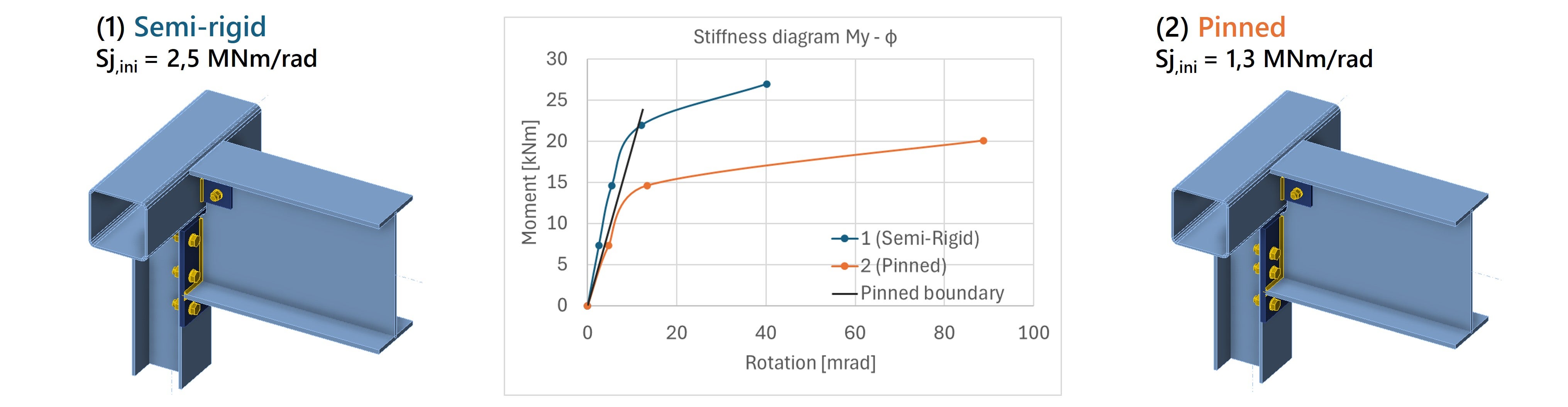
Stiffness analysis
To determine the exact stiffness of the joint, stiffness analysis can be performed with IDEA StatiCa. The moment-rotation diagram is generated and based on the Eurocode, the joint can be classified as fully rigid, semi-rigid, or pinned.
Analyzing the connection of the roof girder for Group D, IDEA StatiCa gives a rotational stiffness that is considered Semi-rigid. This stiffness can be represented in the global structural model using a rotational spring stiffness.
However, if a simple connection is required, the detail must be modified so that the connection is actually classified as Pinned. As shown in the figure below, in situation (2) a hinge has been realized by lowering the top bolt row.
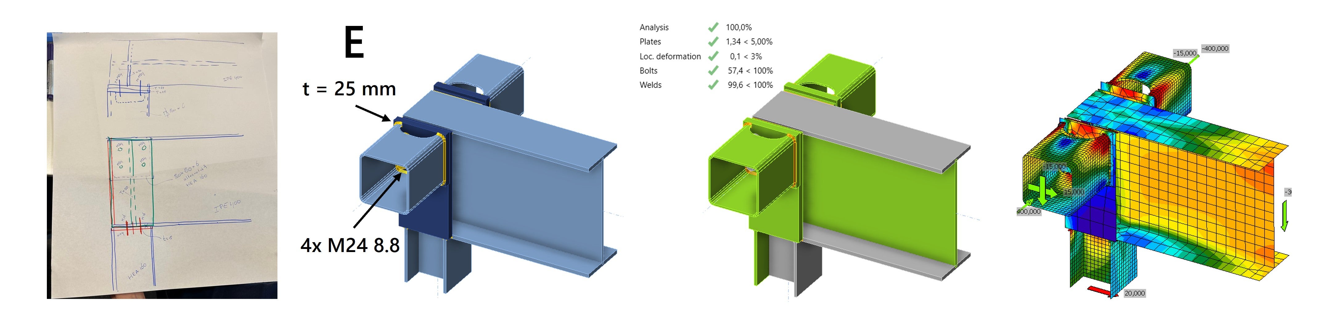
Group E
Group E extended the roof beam and placed it on top of the column. The edge beams were attached to the roof girder with end plates, ensuring that the forces are properly transmitted in the joint.
To allow for the assembly of the bolts, the group proposed a cutout in the hollow section wall. A thoughtful solution, since practicality is a major concern. The cut creates a different stress distribution in the notch, but by applying a round cutout, stress concentrations remain limited.
Group F
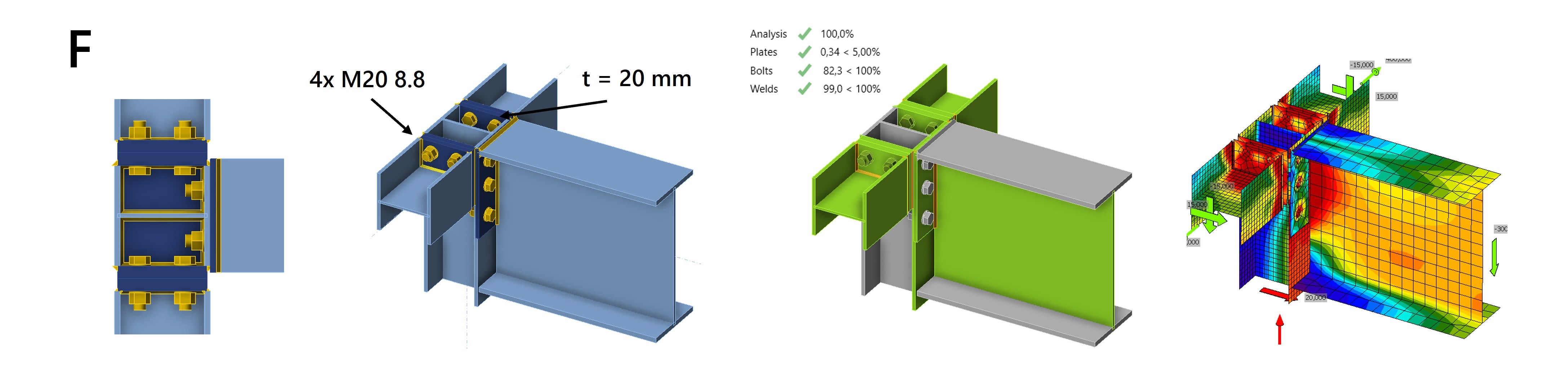
As we have seen, the connection of the edge beams creates design challenges. Group F solves these by replacing the edge beams with HEA160 sections. This makes it easier to connect the beams to the column, and provides sufficient space for mounting the bolts. The connection performs well under compression, and the endplates efficiently channel the forces through the column.
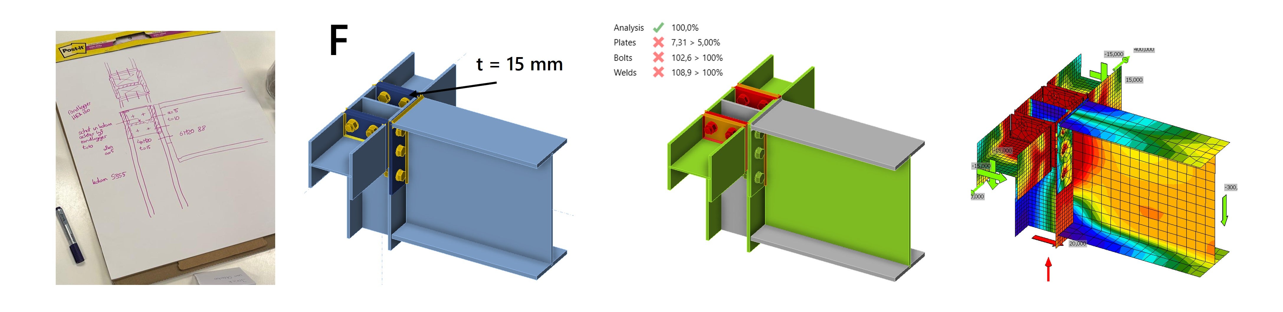
However, the edge beams can also come under a tensile load of 400 kN. In this load case, the connection is not satisfactory. By increasing the thickness of the endplates from 15 mm to 20 mm, the strength requirements are met and the connection is suitable for tensile and compressive loads.
Connection Library
Not sure how to model a specific steel joint? The Connection Library in IDEA StatiCa gives you instant access to dozens of practical examples, helping you find the right solution faster. It's a valuable resource that many structural engineers use as inspiration when designing steel connections.
2 - Design a column baseplate connection with bracing
The second design challenge involves a column baseplate connection. The diagonal bracing can be made in three different profiles and is loaded with a compressive force of 500 kN. The column itself experiences a significant compressive force of 2000 kN.
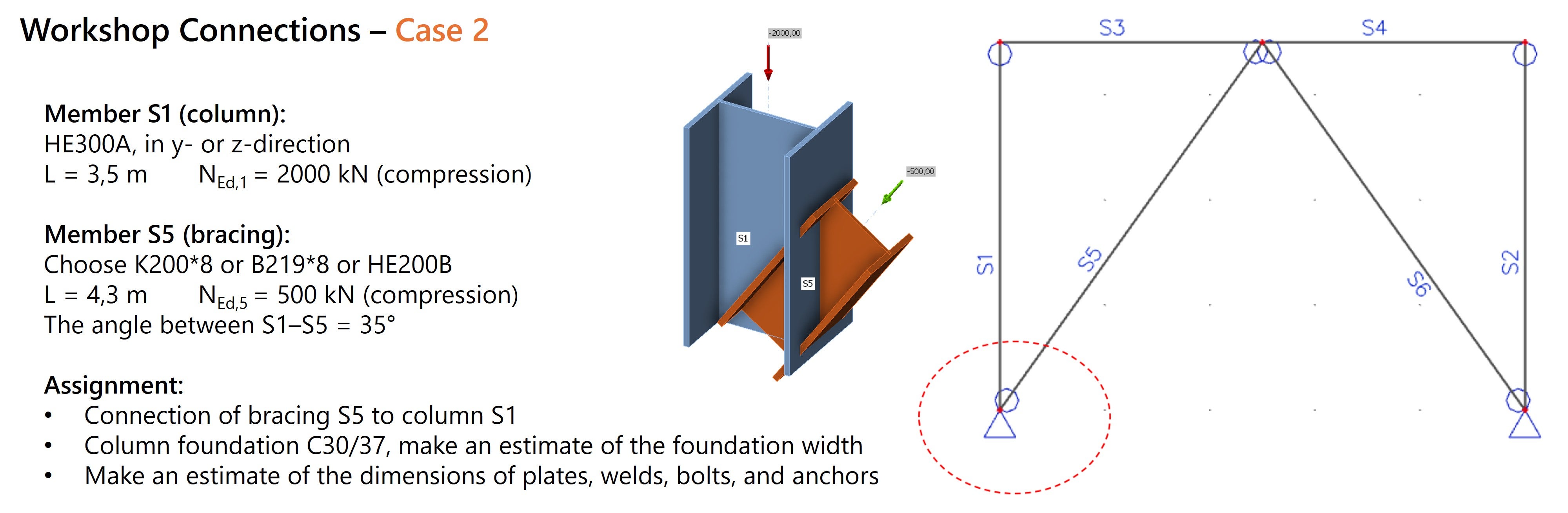
The focus is on the connection between the diagonal and the column, as well as the design of the base plate, including anchors and the foundation. Based on the submitted sketches and presentations, the connections were modeled and analyzed in IDEA StatiCa. Once again, this design shows that multiple connection solutions are possible: there is no single correct answer. Below, we present an overview of the different designs, including the results from IDEA StatiCa. We then discuss the main design considerations, addressing the groups collectively rather than individually.
Connection brace to column
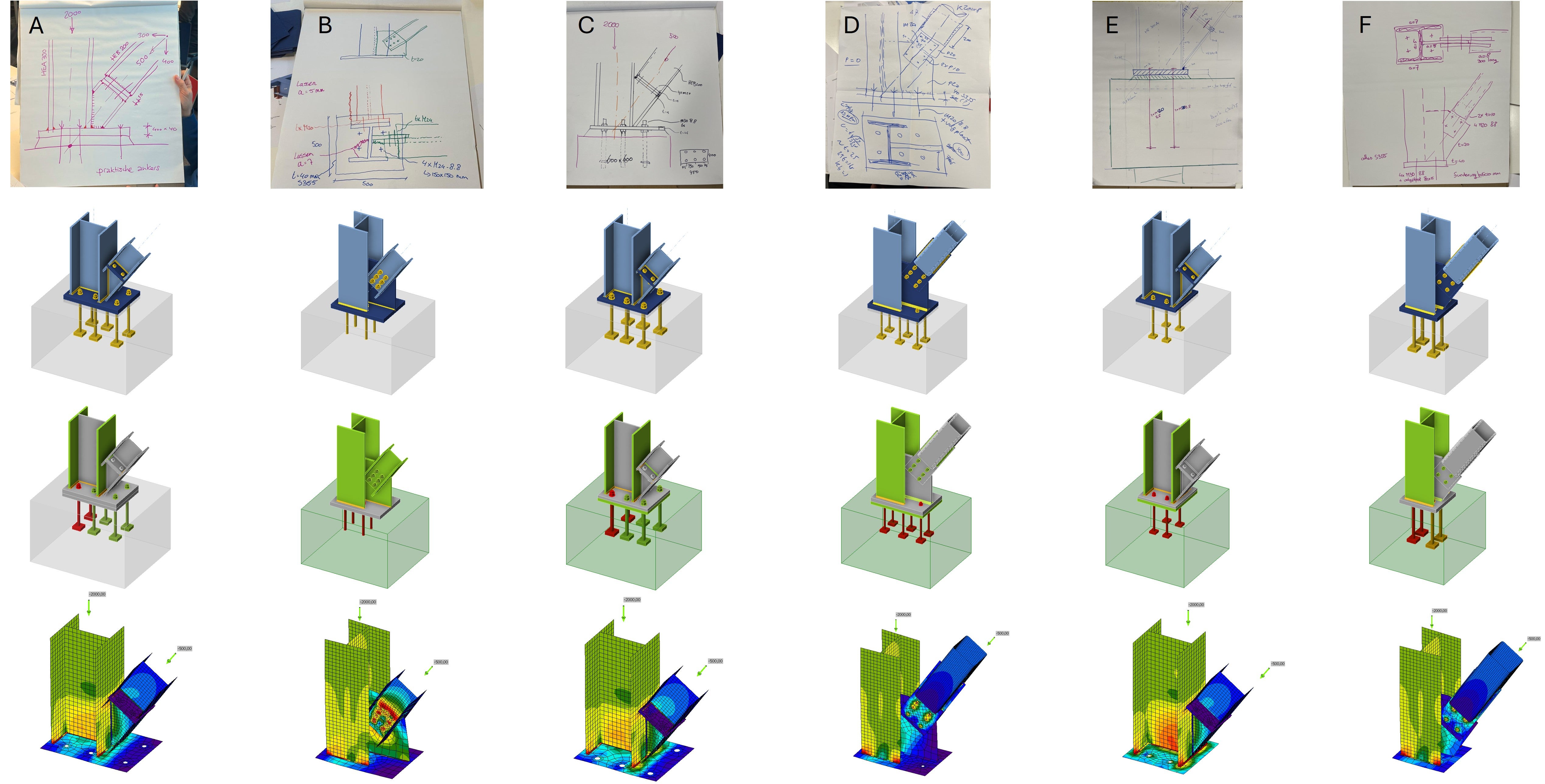
For the connection of the brace, three groups (A, C, E) chose an endplate with stub connection, and the other three groups (B, D, F) chose a gusset plate with bolt connection.
The Stub connection design provides direct transfer of compressive force without complications in the connection. By opting for an HEA profile, bolt assembly is easily feasible and the web of the diagonal member is aligned with the web of the column. As a result, the stresses are well transmitted into the column, as seen in the solutions of groups A, C and E (see figure).
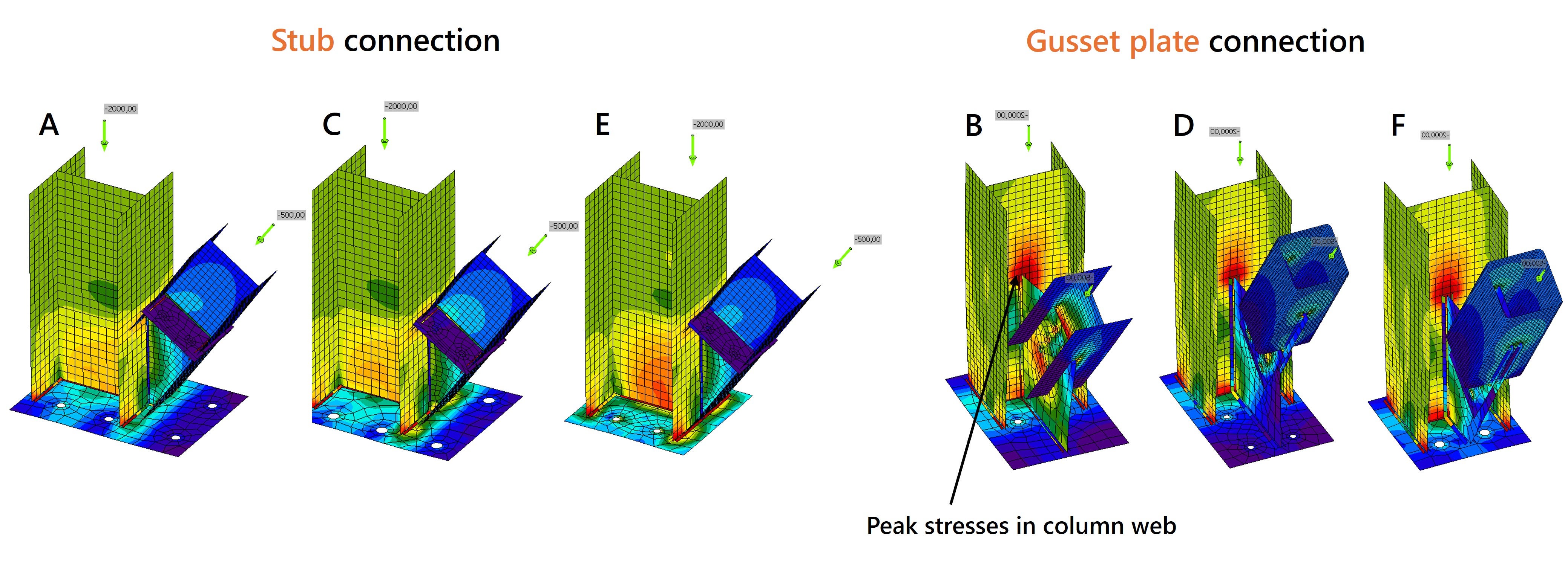
In contrast, Groups B, D and F chose a Gusset plate connection. This considered rotating the column a quarter turn so that the brace can be connected inside the column without taking up too much space. However, in that case, the gusset plate is connected directly, but transversely, to the web of the column, and due to the high compressive forces, peak stresses can then occur in the web of the column. The calculations in IDEA StatiCa show that the design is just within acceptable limits, but the structural engineer should remain cautious. If the web starts to deform plastically, it is advisable to rotate the column, increase the web thickness, or add stiffeners.
In the designs with the gusset plate connection, it is advantageous to make the connection symmetrical and not let the plates protrude too far, for the same reasons we discussed in the first design challenge. Connection B features an asymmetrical layout, but the 20 mm thick plate and the use of six bolts effectively resist the resulting moment, keeping stresses within acceptable limits.
Column base plate design
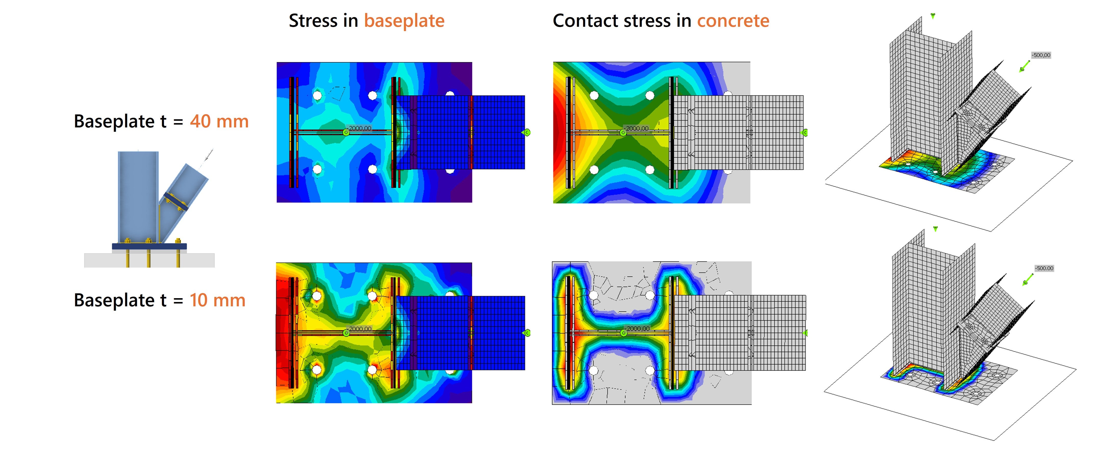
There are also important considerations in the design of the baseplate and concrete foundation. Due to the high compressive forces, it is crucial that the stresses are well distributed through the baseplate into the concrete. This can be achieved by choosing a thicker plate and making it wider than the column profile so that the stresses are better distributed.
The figure below compares the stresses in the baseplate and the contact stresses in the concrete for a baseplate 40 mm and 10 mm thick. If the base plate is too thin, stresses concentrate around the column profile instead of being effectively distributed. As a result, the effective contact area on the concrete becomes too small, leading to compressive stresses that exceed the permissible limit.
Column foundation
We see different foundation solutions, with or without mortar joint, and anchors with or without washer plates. The anchors used range from M20 to M30.
The calculations in IDEA StatiCa show that none of the connections are satisfactory for checking the anchors. As a default, the shear forces are set to be transmitted through the anchors. M20 anchors are found to be insufficiently strong and cannot withstand the shear forces. In contrast, anchors M30 8.8, in combination with a washer plate, are sufficiently strong to transfer the shear forces. Nevertheless, the code-check is still not satisfactory, because the problem is now not in the steel, but in the failure of the concrete.
The shear forces on the anchors cause edge failure of the concrete, with the anchors breaking out of the concrete. IDEA StatiCa Connection calculates with unreinforced concrete, so concrete failure at higher forces is unavoidable.
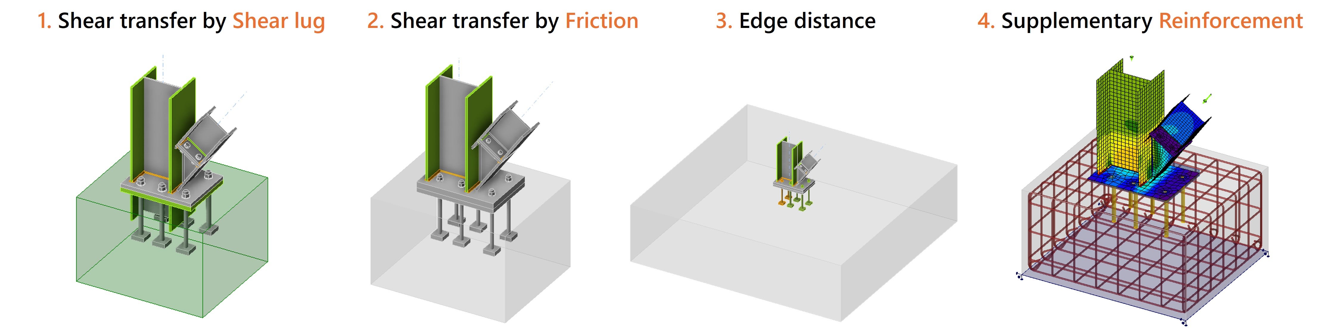
If the forces cannot be reduced, four possible solutions remain.
- Optimize shear force transfer by adding a shear lug. This way, all shear is transferred by the shear key and the failure of the anchors and concrete breakout is avoided.
- Transfer shear forces through friction rather than through the anchors. The high compressive force in the column provides sufficient frictional resistance.
- Modify the concrete block. By increasing the edge distance or concrete class, the concrete is less likely to breakout.
- Design Supplementary Reinforcement in the concrete block. In this way, the steel reinforcement resists tensile forces and prevents concrete breakout. This solution can be modeled and analyzed using IDEA StatiCa 3D Detail.
As shown in the designers’ sketches, only Group E included reinforcement in their design. By adding steel reinforcement to the concrete element, failure mechanisms such as concrete cone breakout and concrete edge failure can be prevented.
Curious how to save time in reinforcement design without compromising safety?
- Or check out this IDEA StatiCa tutorial about Eccentrically loaded anchoring in Detail.
Final word
The steel connections are designed by 6 groups, modeled in IDEA StatiCa and discussed with experienced structural engineers. Using IDEA StatiCa, we were able to analyze the results in detail and identify and discuss important design considerations. This workshop shows that many connections can be designed in an infinite number of ways and that there is never one correct solution. We experienced the importance of drawing to scale and following the path of forces in the connection. Analyzing the stiffnesses and visualizing how the joint will deform is a good thought experiment to understand how a joint will behave.
"Imagination is more important than knowledge" a man named Albert Einstein once said. And that certainly applies to steel connection design as well. Anyone who can imagine what a joint looks like, how it will be made, whether the proportions are right, how the forces will flow and how the connection will deform is already one step closer to becoming the best steel connection designer.
Get 14 days of full access, completely free.
Check out IDEA StatiCa for free