When you need to create a gusset plate connection very quickly, what will you do? You just add a rectangle piece of sheet metal to the main beam and connect the secondary member to this plate. And it's done. So, what's the big deal?
No big deal when 1. you connect one member under tension loading, 2. you have enough space for all connection components, and 3. you don't have to deal with the aesthetics of the connection. All the fun begins with the complexity of the connections, with the compression in members, and with the pressure on the cost and visual side of the task.
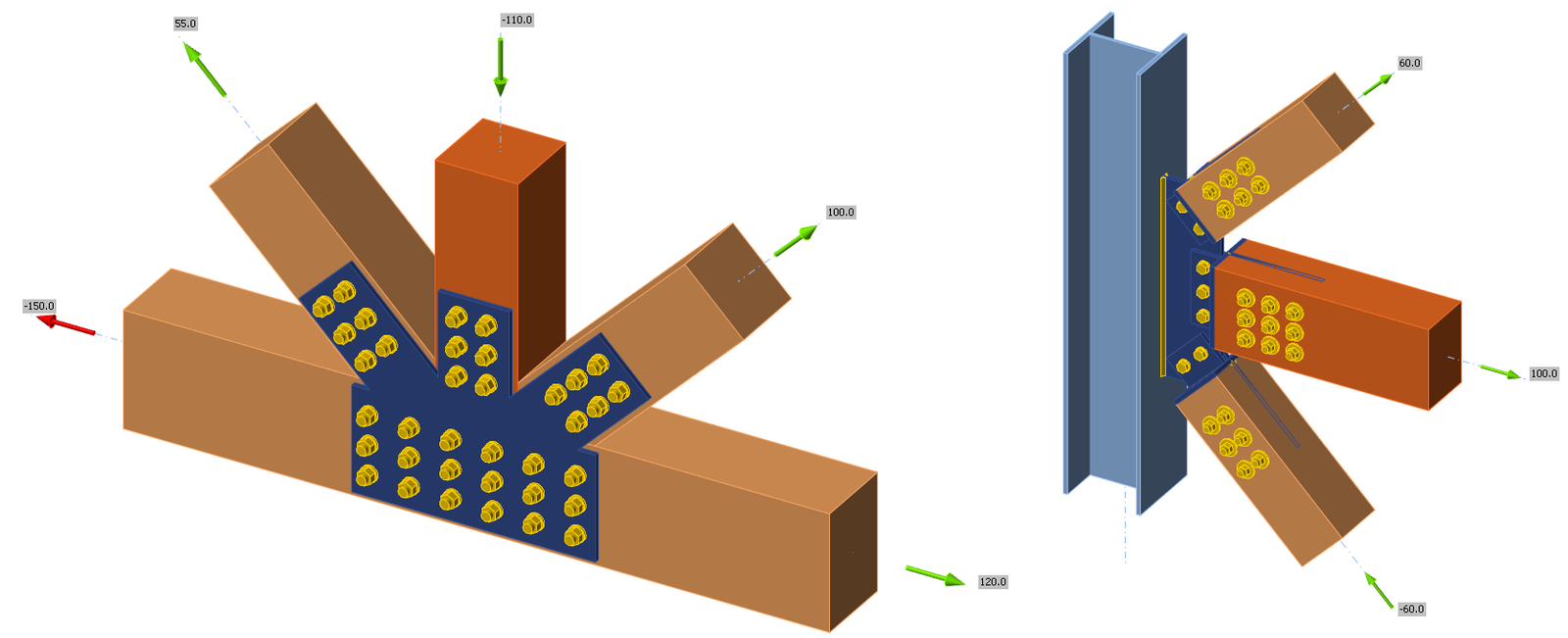
Basic types of gusset connection arrangements
In the following figure, we can see the typical transversal arrangements of the gusset plates in the steel structure connections.
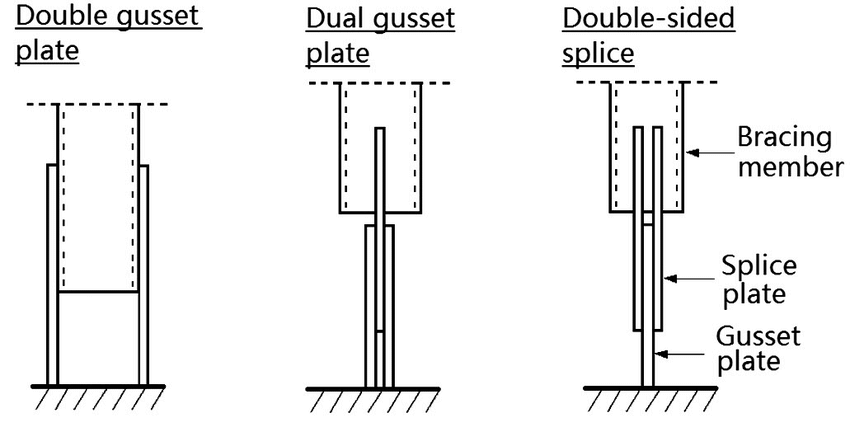
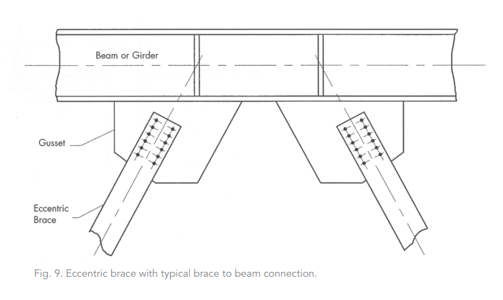
The most common application of gussets could be found in the truss beams and in the lateral bracing systems, where the diagonal members are connected through the gussets.
What's the gusset plate and what's not
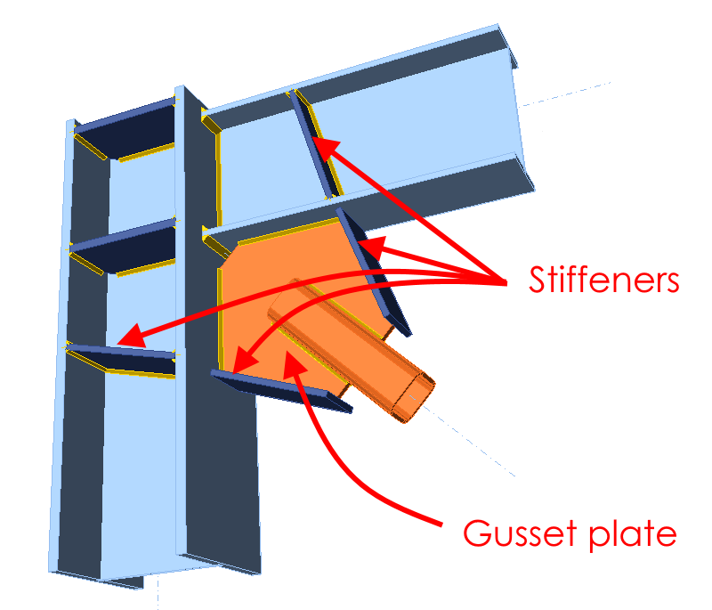
For an inexperienced eye, it could be difficult to find the gusset plate (or gussets) among all the steel components in the connection. Someone could ask, isn't it just another stiffener? Well, it's not.
- The gussets are the crucial parts of the structure, through which all the internal forces from the connected members are transmitted.
- While the stiffeners are important parts needed for correct connection stiffness and for avoiding plate buckling.
- Simply put, if the gusset fails, a disaster hangs in the air. Without the stiffeners, the structure survives (at least for some time).
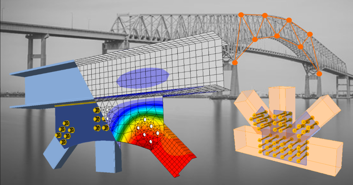
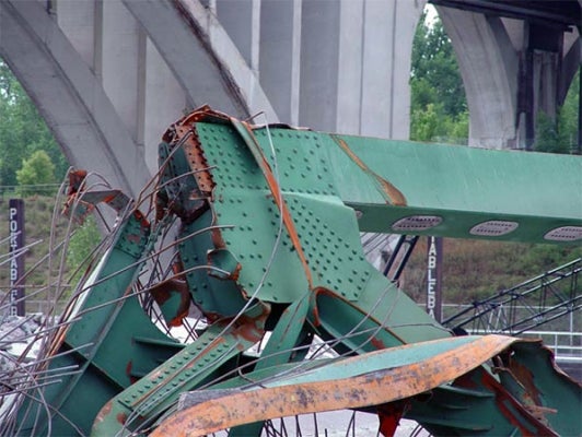
The term gusset plate often comes into the spotlight only after the collapse of a structure or its part. The Interstate 35W Bridge collapse in 2007 was one of such unfortunate events.
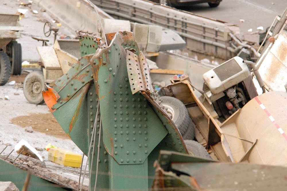
In this case, the main perpetrator has been identified as the unsatisfied design of the truss beams' gusset plates and the lack of these connection parts control during the countless number of bridge inspections. It was simply assumed, that gussets will not be the weakest point in the design and that the gusset plate connections are stronger than the beams that run into the connection. Unfortunately, they weren't.
The design codes give us some manuals on how to check the gusset plate connections' design. Some examples of design codes with specifications for gusset plates:
- AISC 360-16 (United States)
- CSA-S16-09 (Canada)
- EN 1993-1-8 (European environment)
These manuals are based on an analytical approach, which is quite easy to apply but can be very time-consuming with the increasing number of connection types or alternatives.
Members in tension
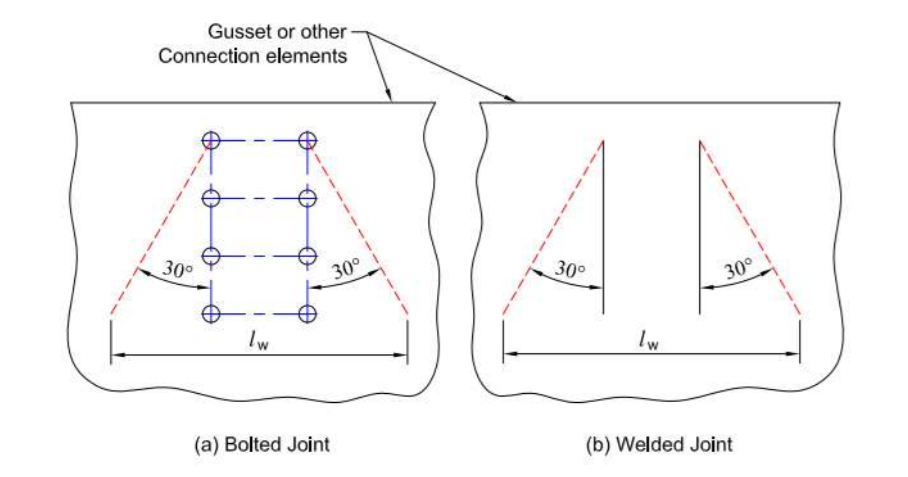
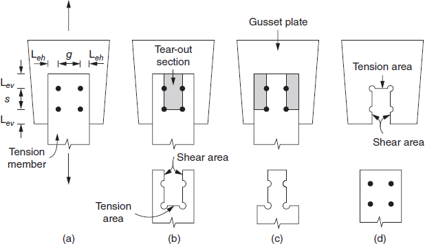
The tension members' connections are, let's say, the easy ones. But the engineer still has to do a number of checks on gusset plates. As an example, the Whitmore cross-section should be checked for the tension forces.
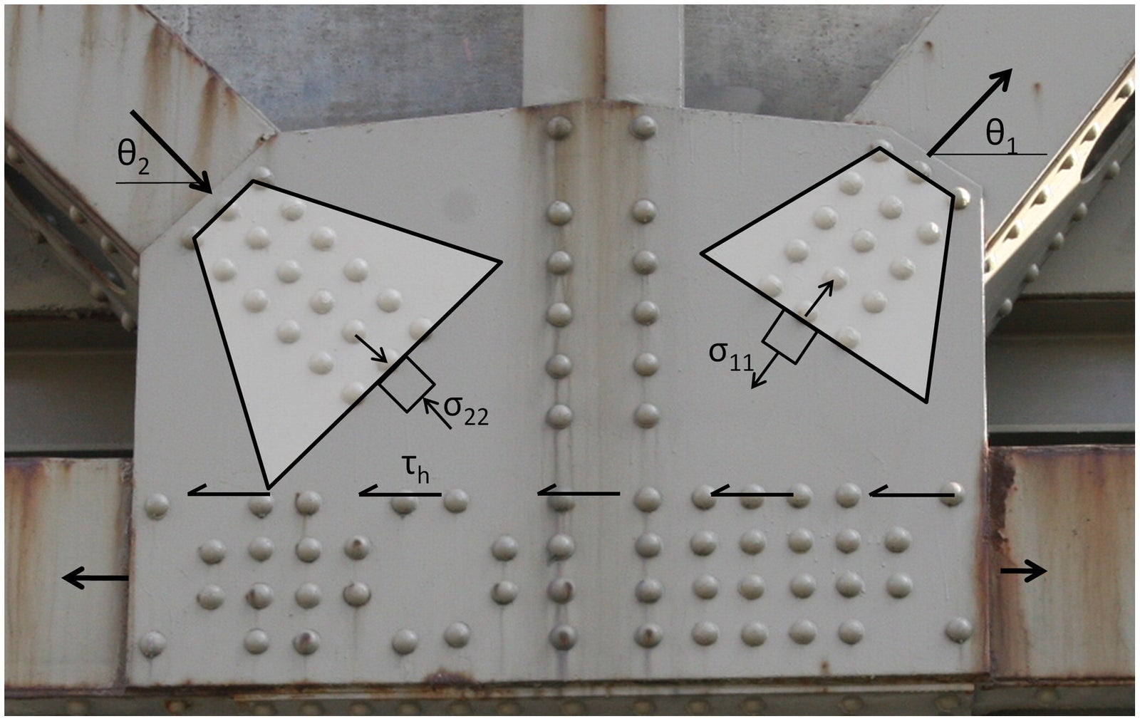
How it looks on paper:
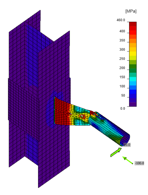
And in the real structure:
Another check is related to the block shear failure in a connection, which involves both shear and tension components and is specified in AISC 360 Sec. J4.3. As a connection designer, you have to check all possible shear failure paths in the bolt grids, as you can see in the example given below.
You can find one nicely prepared example of block shear resistance assessment in this verification article.
Members in compression
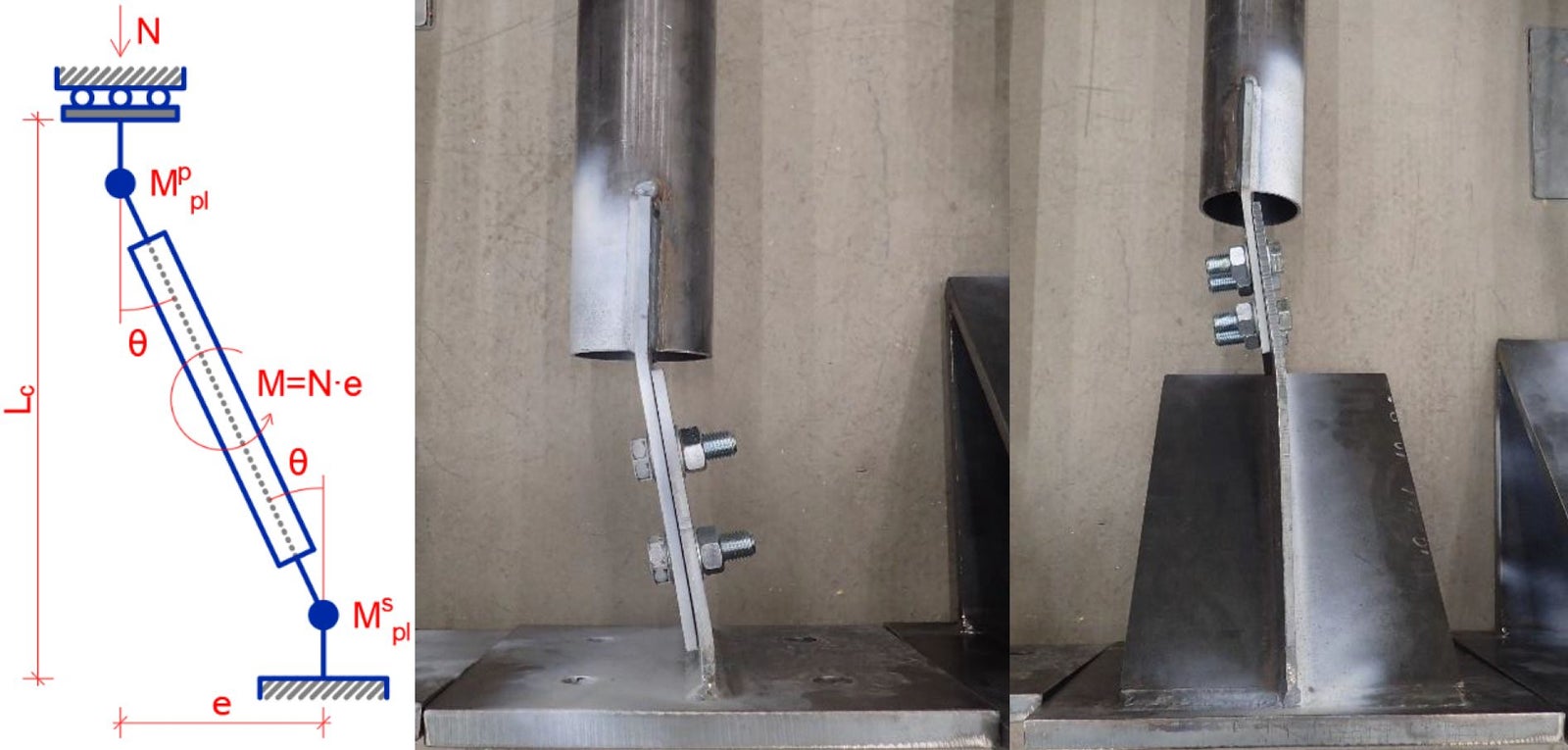
The gusset connection design can become a completely different "sport" when it comes to compression members. We still have to check all the shear failures, but the buckling problem starts to play a much more important role.
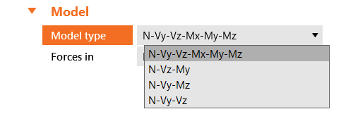
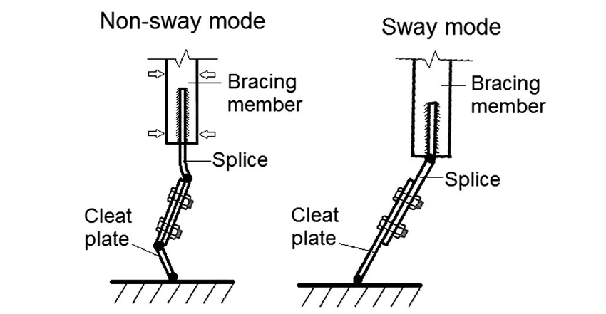
A crucial parameter in the compression member connection design is the fact of whether the member can or can not sway out of the gusset's plane. This will influence the behavior of the failure mechanism and the creation of the plastic hinges in the plates. In IDEA StatiCa Connection, you can set this behavior for every particular member simply by selecting the correct Model type.
The failure modes for these two different situations are shown in the following figure.
This could be solved by an analytic approach as well, but you'll probably spend a lot of time with every single connection arrangement. More probably, the engineer will save precious time by simply avoiding this situation, and will add some stiffeners. It's an understandable, but costly solution.
Using some smart tool providing the stability check for such connections is another way. The buckling analysis is an elementary part of the IDEA StatiCa Connection app and provides you with buckling shapes and load factors for a user-defined number of shapes.
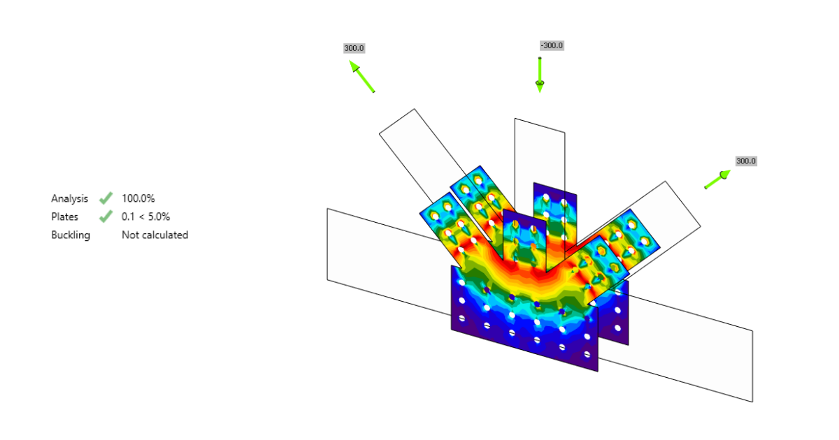
Research
In IDEA StatiCa development, there is no place for a trial & error approach. All the methods used in the applications and calculation models are verified on real structure testing and further analyzed in cooperation with reputable universities.
One such research was dedicated also to the gusset plate connection design. The results of the tests were compared with the CBFEM modeling with a very good correlation. Here you can find our verification article with the outcomes of the research.
How to be effective and competitive
So what are your options when it comes to the need for connection design in accordance with the standards, but also when you need to do your designs and checks not in months but within weeks? Moreover, you need to be flexible for revisions during the project and you want to compare several arrangements in a reasonable time. Do you also want to have your connections easily assembled and not cost a fortune?
You already know the right answer, we need to use some 21st-century tools, which will do most of the uncreative work for us. If we want to have our hands really free in the design, the number of options narrows significantly.
You could simply try to use IDEA StatiCa Connection and you'd find out that it's all you need for the job. Or you can follow the standard learning path:
- First, just use some Excel spreadsheets,
- then try some more sophisticated spreadsheet-based connection software,
- when you're on the limits, spend some time with experiments on something even more sophisticated,
- maybe create some detailed shell models in your FEA applications
- and after all these trials, go for IDEA StatiCa Connection application anyway.
After this path, you will fully appreciate all its benefits.
Short video tutorial dedicated to connection with gussets
When it comes to cost estimation, it can be really tricky to calculate the price for every connection these days. In IDEA StatiCa app, this information comes out almost like a pleasant side effect. In this article, you will find all the necessary tips on how to use this feature.
Another typical use of gusset plates
Thanks to the arrival of CNC machining also into the civil construction workshops, the gusset plates are one of the main ways to connect not only steel members but the timber members as well. Instead of tailoring complicated members' end shapes, we can just simply input a steel plate with holes. The timber members are prepared with CNC-made holes and grooves, and the connection is finally assembled with steel pins and bolts.
The next level in the structural design evolution is to combine structural materials and use the best of their properties in the right place. That's how the hybrid timber-steel structures arose. Besides its natural visual beauty, there are many other reasons for its usage, such as cost reduction, lower need for fire protection, or reducing the carbon footprint.
For those, interested in steel-to-timber design, read more about the timber connections solved in IDEA StatiCa Connection in our Support Center.
IDEA StatiCa is proud to be in the front line for the connection and structural member design. If you have an idea of how the gusset plate design could be improved, let us know.
Get 14 days of full access, completely free.
Check out IDEA StatiCa for free