The 'simple' splice connection
When I was asked to write a blog article about the splice connection I thought “great”. It was one of the very first connections I designed way back when I was at university.
Much has changed since then (including the use of computers).
A splice is something that joins one item to another. We see this every day but probably don’t realize: how long can a cable or drain or a brake line on a train be? All things have a finite length or weight. Sometimes there is an imposed limit on how long or heavy something can be. A splice is a way of increasing that length or weight.
In steelwork that takes the form of increasing the length of a column or a beam or even a truss. As we introduce these splice joints, we can utilize greater efficiency in design by increasing the size of a column as we go down or by splitting a long beam into smaller ones to allow for easier installation. Understanding the constraints and forces involved is one thing being able to apply them correctly is another. This is where IDEA StatiCa can greatly help with the workflow by examining the various conditions and load cases to make sure the joint is both safe and efficient.
Splice joint
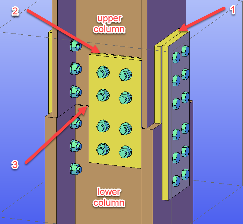
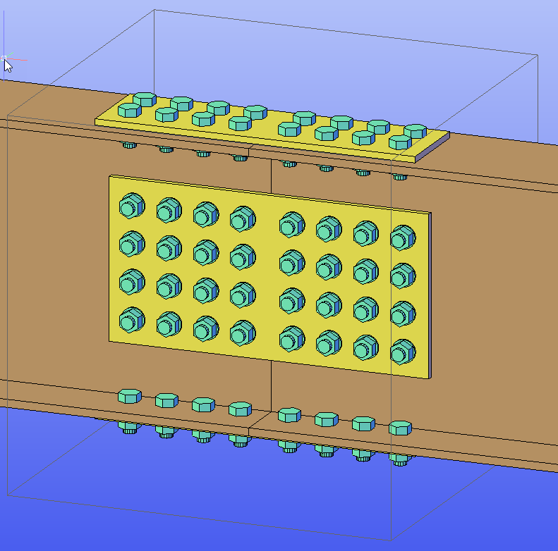
When we think about a splice joint we generally gravitate towards a column splice. This example highlights the interaction between construction, analysis and documentation, which is often put to one side or considered as an afterthought. When we start to think about positioning these joints it is usually after the initial modeling and global analysis. Herein lies a possible problem: should these joints be modeled in the correct locations from the start and with the correct parameters?
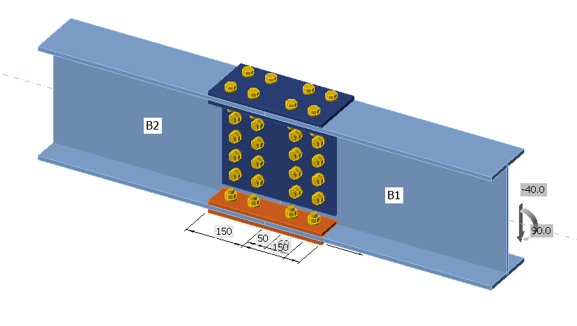
If we assume we have a multi-story steel frame then there is a finite length we can obtain columns and these are usually split after two (and a bit) stories. Then the lift above will generally have a smaller column section. On a set of floor plans we will see the change in column section. If the same model is used (or even re-created) for analysis and design then the change in column will probably be coincident with the floor beams. The splice cannot be positioned at the same location as the floor beams but at a designated offset – this reflects how the building is being constructed.
This begs the question what is happening to the forces at this offset? How do they compare with the assumed location? What are the requirements of the connection? All this is before we are looking at the fabrication requirements of the splice which many forget about: flange packers (1), web packers (2), grinding flush to achieve (near) perfect contact or top plates (3).
Beam splice
When examining a beam splice we see far too many where they are positioned for ease of access: in the middle of the span. Not a good idea at the best of times. Engineers have an obligation to design safely and this requires an understanding of how the beams are going to be installed - hence the need for beam splices (especially on smaller projects). However, if done badly beam splice design can have a catastrophic effect on the operation of a building. Using the wrong bolts can lead to slippage in the clearance holes increasing the deflection. Bolts have been known to fall out if load reversal or vibrations have not been taken into account. Bolt orientation is sometimes as important as having the right type of bolt.
Forces in splice joints
The forces that we should use in the design of any splice should be the forces at that location. That makes perfect sense. An overall frame analysis that has used incorrect assumptions will also give incorrect results. In IDEA StatiCa Connection there is the concept of a supporting (or Ended) member. This is the member that effectively supports another. This is the red square that appears at the end of the member. Load effects are then applied to the members that form the splice.
With the right members, in the right location and with the correct load effects applied IDEA StatiCa will code check your splice connection to one of several codes from around the world. But it can only do so with the engineer in control.
It is only right that we discuss the role of the analytical model - after all without this we wouldn't know the size and material of the members concerned or the forces acting on them. IDEA StatiCa has a set of BIM links that can greatly streamline the workflow and also safeguard using the correct members and forces from the load case combinations that were used in the analysis model. The less re-creation of a model we have to do the better with the additional benefit that we virtually eliminate the risk of entering the wrong figures and the applied forces are in equilibrium or balanced.
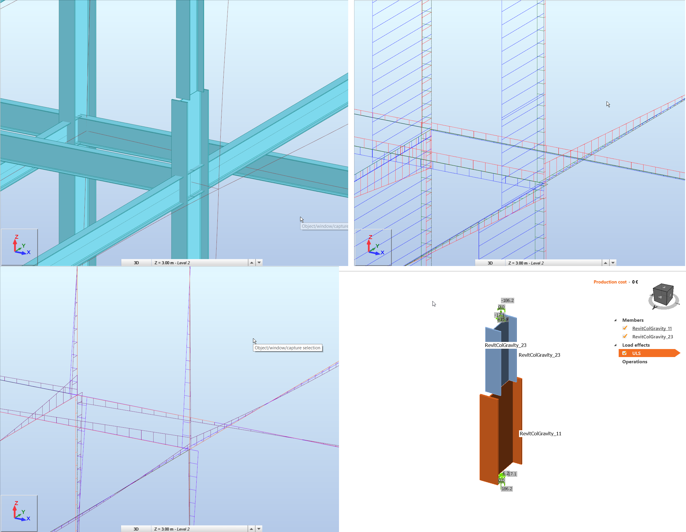
Going clockwise from top-right: deflected shape, shear forces, moments, all pulled into IDEA StatiCa. With the correct approach, you can design splices very easily with IDEA StatiCa Connection.