This is the follow-on article to the one taking a look at trusses written by my colleague – Ralph Pullinger. Firstly, the ultimate question is – what is the difference between bracing and truss? There is a little bit of a cross-over on these topics, as you might imagine.
Essentially, a brace is a single member that supports, strengthens, or reinforces something while a truss is usually a whole part of the structure and is formed by many members. In other words, bracing can be a part of a truss structure. Of course, some truss systems necessarily require braces to make them complete – especially in the housing market. Even members within some trusses act as braces.
But where are they found, and is the bracing system used only in steel structures? Not at all. You will usually find them in steel as well as timber-framed buildings. Less so in a concrete frame, unless there are specific reasons, such as a retrofit or strengthening.
Bracing systems used in steel structures
In steel structural systems, a brace is usually defined as taking axial load only (either compression or tension). If a brace was to take a moment, then this would mean that it should be defined as a beam or column. Braces are not restricted to the horizontal or vertical axis. They are also used within inclined planes (such as a roof plane). Braces invariably transfer actions. Predominantly, they aim to transfer horizontal load, such as wind, down to a supporting mechanism – usually foundations.
Braces can take the form of wires, strips, angles, rods, hollow sections, and even I sections. They were traditionally always conceived to be hidden, but there are also several examples of them being exposed and enhanced.
A beautiful example of architectural and structural engineering symbiosis revealing the bracings and its brace connection details on the façade can be found in Spain on the building nowadays known as the Hotel Arts Barcelona. Here, the structural steel connections are almost close enough to touch and are observable by the hotel guests. See how we performed this bracing design calculation in one of our webinars.
During the olden days of 2D (both analog and digital) and, due to the plane they operate in, bracings were also frequently forgotten until they were spotted going in front of a window (unintentionally) or blocking door access. How many remember those situations?
Now, with the advent of BIM, these coordination issues have all but disappeared (hopefully). The uptake of FEM has also seen a more efficient use of material, and more rigorous analysis methods enable engineers to locate bracing systems where they will work better.
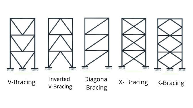
In its simplest form, a brace is a member that goes from one location to another. It may be a single brace or be part of a larger system of bracing forming a pattern. Of course, there is a full variety of bracing systems used in structures, from the typically used X-bracings to advanced systems respecting architectural requirements.
An engineer's training and experience will usually guide them to find suitable positions and forms of bracing. This can be further refined with analysis. It is during this analysis that additional effects, such as eccentricities, are assumed negligible. As I always maintain – an engineer likes to keep things simple.
In the global structural analysis (2D or 3D frames), you will see beams, columns, and bracing all meeting at one node. In reality, this cannot be the case as there is always some eccentricity involved. This can also be modeled in FEM and BIM so that these effects are considered – usually, a nudge up/down or left/right will suffice.
Read more in the blog from Jan Kubicek about structural eccentricities and their problems – What if it doesn’t go in the right direction?
Types of bracing connections in steel structures
Now, we have a series of braces that can take the design load – how do we connect them to the main structure? This is where the art of detailers and their knowledge comes in. What are the limitations here? Simply put, how many types of connections in steel structures the detailer has stored in his hippocampus, of course, his/her creativity, but also what are the limitations of the software tools used?
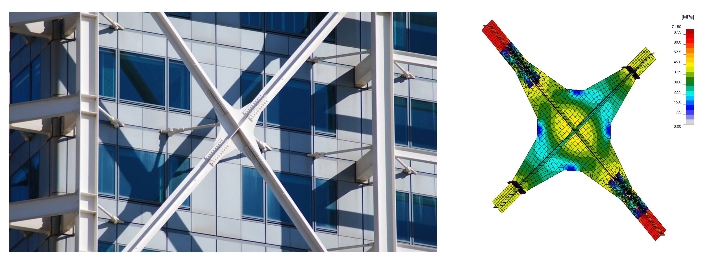
There are many examples of typical arrangements that do this task. Most do not stand out from the crowd, but some do. The example below is taken from the case study and webinar Facade connections at Midland Metropolitan hospital.
The client wanted to make a feature out of the bracing system and used IDEA StatiCa to create a functional and appealing connection.
This would be a great example of how IDEA StatiCa could utilize both a geometric model (BIM) from say Tekla Structures to get the member positioning and shapes of the various plates with using the load effects via FEM from say, SCIA Engineer (other CAD and FEM solutions are available😊). But hey, this really is possible!
Brace connection details in IDEA StatiCa
The application for connection design and code-check IDEA StatiCa Connection is, of course, fully capable of providing any type of geometry and loading, starting with simple connections as for the typical V-bracing system. The strong side here compared to say Excel spreadsheets is the quick generation of the detail shape, the possibility of fast optimization, full visual control, and not least, the buckling analysis!
Read more about buckling for not only bracing connections in the article Buckling needs critical thinking! from the author Jana Kaderova.
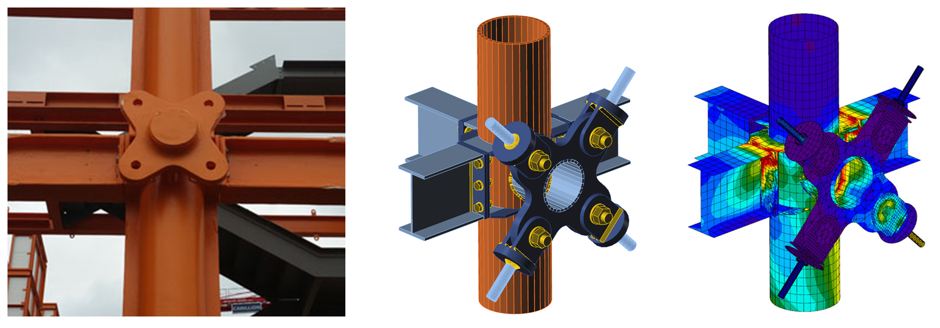
Next to the standard ones, our app has proven its skills against boss-level connections as well. Here, it comes to the game where the architect makes his/her sweet dreams come true, and the structural engineer suffers a nightmare. Such X-bracing central rings are used in many variants, from the standardized manufactured and tested to absolutely custom ones needing to be fully analyzed and code-checked.
Under the heading of braces, we also see one of the frequent reasons for messages to our helpdesk. The above examples also show a single bolt connection from the brace to the structure. As such, this member cannot take any moment, but just a normal force and shear forces.
In the steel connection software IDEA StatiCa Connection, the parameter of the bracing member called the Model type must be changed from the default N-Vy-Vz-Mx-My-Mz to N-Vy-Vz (no moments). Otherwise, a singularity will occur due to the mechanism formed around the bolt.
Very verified solution
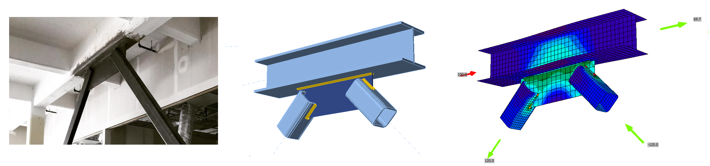
A few days back, as part of my helpdesk duty, I was solving a problem with a connection that was standard/non-standard. That depends on your point of view. The connection model was a simple fully welded hollow sections (RHS) K-joint, and the customer was discussing the lower load-bearing capacity of this bracing connection calculated in the Connection app compared to hand calculations.
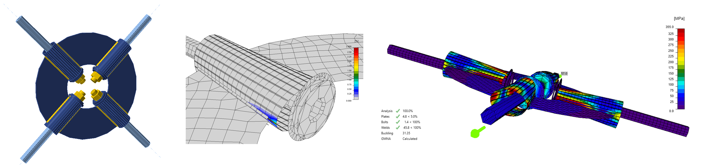
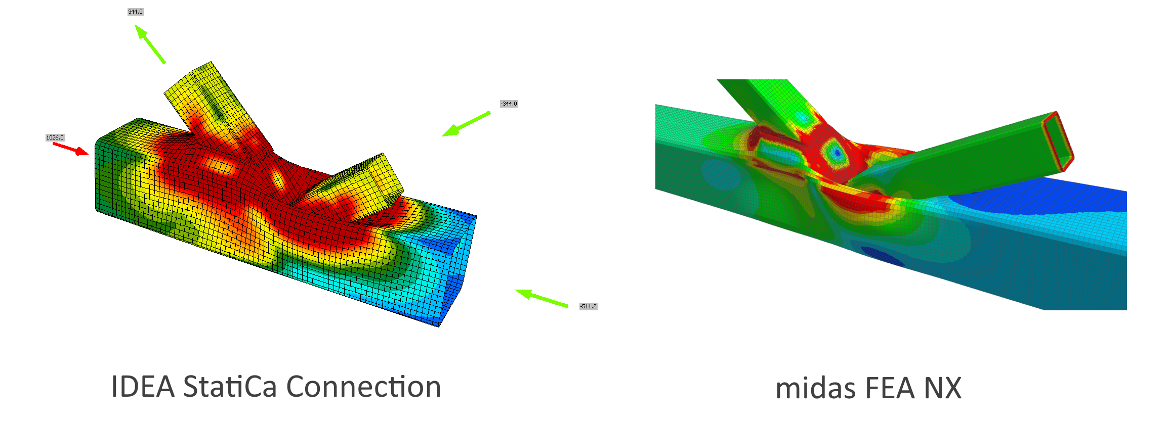
In this part of the story, it is important to point out that the CBFEM-based solution in the software is fully verified on multiple levels, including laboratory tests and many examples used. Nevertheless, we reacted with a thorough inspection of the problem and by providing an independent finite element model composed of 3D solid elements with geometrically non-linear elastoplastic behavior in the software midas FEA NX.
The assumptions for both models:
- Steel S355 – a bilinear diagram with hardening
- Geometrical and material nonlinear analysis
In general, manual calcs provided by the code tend to be rather conservative. In this very case, it is vice versa, and the double-checked finite element solution providing a precise model simply displays a lower capacity by about 20% in both numerical models compared to the hand calculations. In conclusion, this is due to the spatial deformations and punching of the main beam.
Next to this, in our Support center among the list of verification and research articles, there are ones discussing solely bracings as well.
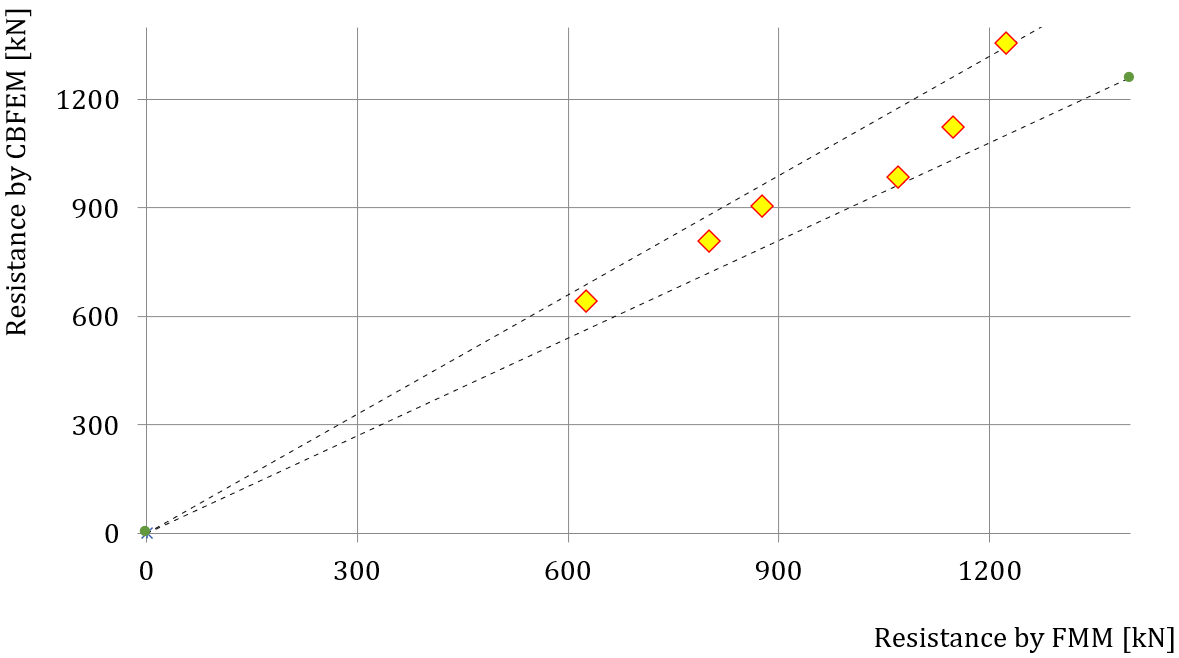
One of them, Rectangular hollow sections, also includes the very example of the welded K-joint designed under Eurocode. The work shows the research outputs of the Connection app results comparison against the traditional method, in other words, resistance determined by CBFEM to FMM for the uniplanar SHS K-joint
For the US code AISC, there are a couple of verification examples prepared by Mahamid Mustafa in a joint project between The University of Illinois in Chicago and IDEA StatiCa. The Chevron Brace Connection in a braced frame (AISC) text, as well as the others, very well reveals the safe yet efficient concept of the CBFEM method.
The end?
Thank you for taking the time out to read this article, and we hope to see you again soon in our IDEA StatiCa blog!
PS: A bonus quiz 😊. Try to count how many steel bracings you can find in our Sample projects gallery!
3,2,1,...
... alright, here is the complete filtered list of them for download, inspection, and free usage.