
Ultimate limit state analysis
The different verifications required by EN 1992-1-1 are assessed based on the direct results provided by the model. ULS verifications are carried out for concrete strength, reinforcement strength, and anchorage (bond shear stresses).
The concrete strength in compression is evaluated as the ratio between the maximum principal compressive stress σc = σc2 obtained from FE analysis and the limit value σc,lim = fcd.
The strength of the reinforcement is evaluated in both tension and compression as the ratio between the stress in the reinforcement at the cracks σsr and the specified limit value σs,lim:
\(σ_{s,lim} = \frac{k \cdot f_{yk}}{γ_s}\qquad\qquad\textsf{\small{for bilinear diagram with inclined top branch}}\)
\(σ_{s,lim} = \frac{f_{yk}}{γ_s}\qquad\qquad\,\,\,\,\textsf{\small{for bilinear diagram with horizontal top branch}}\)
where:
fyk yield strength of the reinforcement according to EN 1992-1-1 Cl. 3.2.3,
k the ratio of tensile strength ftk to the yield stress,
\(k = \frac{f_{tk}}{f_{yk}}\)
γs is the partial safety factor for reinforcement
The bond shear stress is evaluated independently as the ratio between the bond stress τb calculated by FE analysis and the ultimate bond strength fbd, according to EN 1992-1-1 chap. 8.4.2:
\[\frac{τ_{b}}{f_{bd}}\]
\[f_{bd} = 2.25 \cdot η_1\cdot η_2\cdot f_{ctd}\]
where:
fctd is the design value of concrete tensile strength according to EN 1992-1-1 Cl. 3.1.6 (2). Due to the increasing brittleness of higher-strength concrete, fctk,0.05 is limited to the value for C60/75 according to EN 1992-1-1 Cl. 8.4.2 (2)
η1 is a coefficient related to the quality of the bond condition and the position of the bar during concreting (Fig. 31).
η1 = 1.0 when ‘good’ conditions are obtained and
η1 = 0.7 for all other cases and for bars in structural elements built with slip-forms, unless it can be shown that ‘good’ bond conditions exist
η2 is related to the bar diameter:
η2 = 1.0 for Ø ≤ 32 mm
η2 = (132 - Ø)/100 for Ø > 32 mm
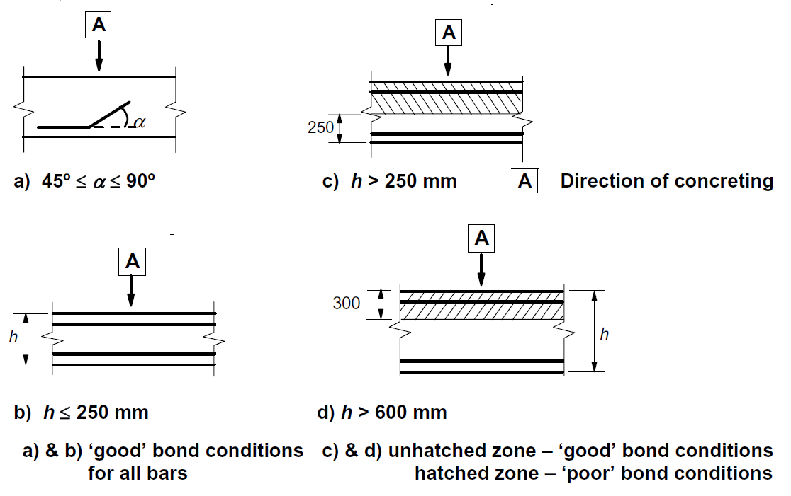
\[ \textsf{\textit{\footnotesize{Fig. 31\qquad EN 1992-1-1 Figure 8.2 - Description of bond conditions.}}}\]
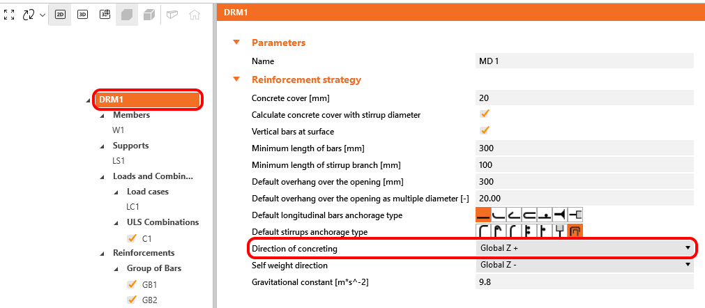
In IDEA StatiCa Detail the bond conditions are taken into account according to Fig. 31 c) and d). The direction of concreting can be set in the application for each project item as follows.
These verifications are carried out with respect to the appropriate limit values for the respective parts of the structure (i.e., in spite of having a single grade both for concrete and reinforcement material, the final stress-strain diagrams will differ in each part of the structure due to tension stiffening and compression softening effects).
There is also an option to model smooth rebars. More information can be found here: Smooth rebars in Detail
Total force Ftot and Limit force Flim
The total force Ftot is a result of the finite element analysis and can be defined in two ways.
\[F_{tot}=A_{s}\cdot \sigma_{s}\]
where As is the area of the reinforcement bar and σs is the stress in the bar.
Or as a sum of the anchorage force Fa and the bond force Fbond.
\[F_{tot}=F_{a}+F_{bond}\]
where Fa is the actual force in the anchorage spring and Fbond is the bond force that can be obtained by integrating the bond stress τb along the length of reinforcement bar l.
\[F_{bond}=C_{s} \cdot \int_{0}^{l}\tau_{b}\left( x \right)dx\]
Cs is the circumference of the reinforcement bar.
The limit force Flim is the maximum force in the element of the rebar considering the ultimate strength of the rebar and also anchoring conditions (bond between concrete and reinforcement and anchorage hooks, loops, etc.).
\[F_{lim}=min\left( F_{lim,bond}+F_{au},F_{u} \right)\]
\[F_{u}=k\cdot f_{yd}\cdot A_{s}\]
\[F_{au}=\beta\cdot k\cdot f_{yd}\cdot A_{s}\]
\[F_{lim,bond}=C_{s}\cdot l \cdot f_{bd}\]
where Cs is the circumference of the reinforcement bar, and l is the length from the beginning of the rebar to the point of interest.
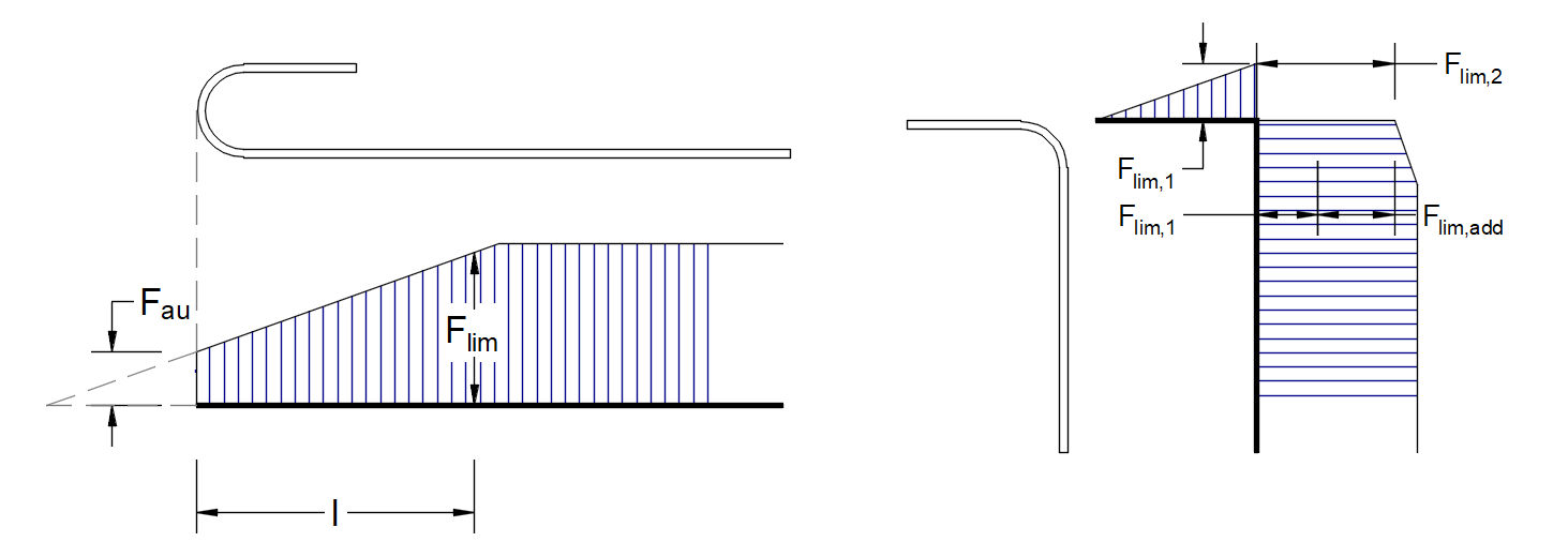
\[ \textsf{\textit{\footnotesize{Fig. 32\qquad Definition of the limit force Flim}}}\]
\[F_{lim,2}=F_{lim,1}+F_{lim,add}\]
where Flim,add is the additional force calculated from the magnitude of the angle between neighboring elements. Flim,2 must be always lower than Fu.
The available anchorage types in the CSFM include a straight bar (i.e., no anchor end reduction), bend, hook, loop, welded transverse bar, perfect bond, and continuous bar. All these types, along with the respective anchorage coefficients β, are shown in Fig. 32 for longitudinal reinforcement and in Fig. 33 for stirrups. The values of the adopted anchorage coefficients are in accordance with EN 1992-1-1 section 8.4.4 Tab. 8.2. It should be noted that in spite of the different available options, the CSFM distinguishes three types of anchorage ends: (i) no reduction in the anchorage length, (ii) a reduction of 30 % of the anchorage length in the case of a normalized anchorage and (iii) perfect bond.

\[ \textsf{\textit{\footnotesize{Fig. 33\qquad Available anchorage types and respective anchorage coefficients for longitudinal reinforcing bars in the CSFM:}}}\]
\[ \textsf{\textit{\footnotesize{(a) straight bar; (b) bend; (c) hook; (d) loop; (e) welded transverse bar; (f) perfect bond; (g) continuous bar.}}}\]
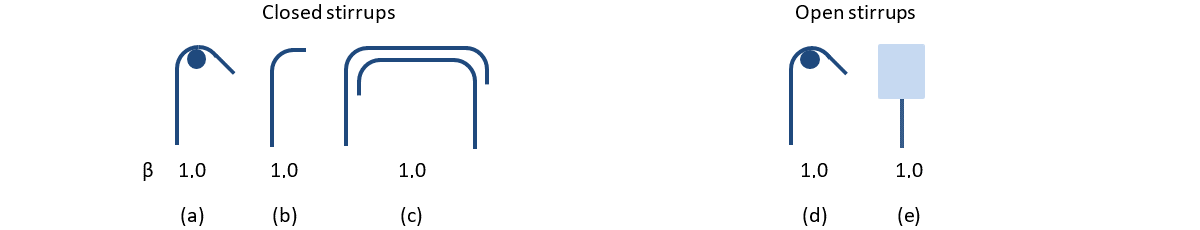
\[ \textsf{\textit{\footnotesize{Fig. 33\qquad Available anchorage types and respective anchorage coefficients for stirrups.}}}\]
\[ \textsf{\textit{\footnotesize{Closed stirrups: (a) hook; (b) bend; (c) overlap. Open stirrups: (d) hook; (e) continuous bar.}}}\]
In order to comply with EN 1992-1-1, the anchorage spring should be used in the calculation, the anchorage spring is modified by the β coefficient so the user must use one of the available anchorage types when defining the reinforcement start and end conditions.