
Tekla Structural Designer BIM link for connection design (EN)
How to activate the link
- Download and install the latest version of IDEA StatiCa
- Make sure that you are using a supported version of your FEA solution
In Tekla Structural Designer 2022 SP2 (July 2022) and newer, the IDEA StatiCa Checkbot command is embedded in the application, and no installation of the BIM link is necessary. For more information, refer to the release notes.
How to use the link
Download the attached project, open it in Tekla Structural Designer 2022.2 or later, and run the calculation to get the internal forces over the structure.
First, create connections at nodes within Tekla Structural Designer. Navigate to the Connections window, right-click within it, and select Update Connections.
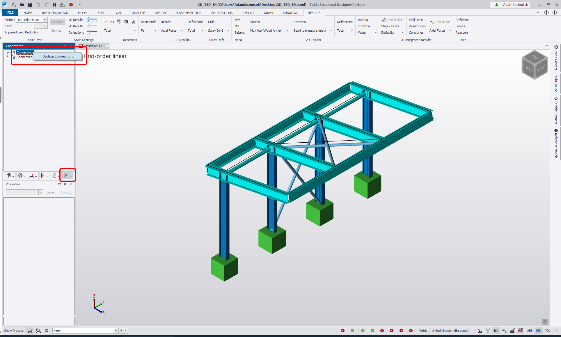
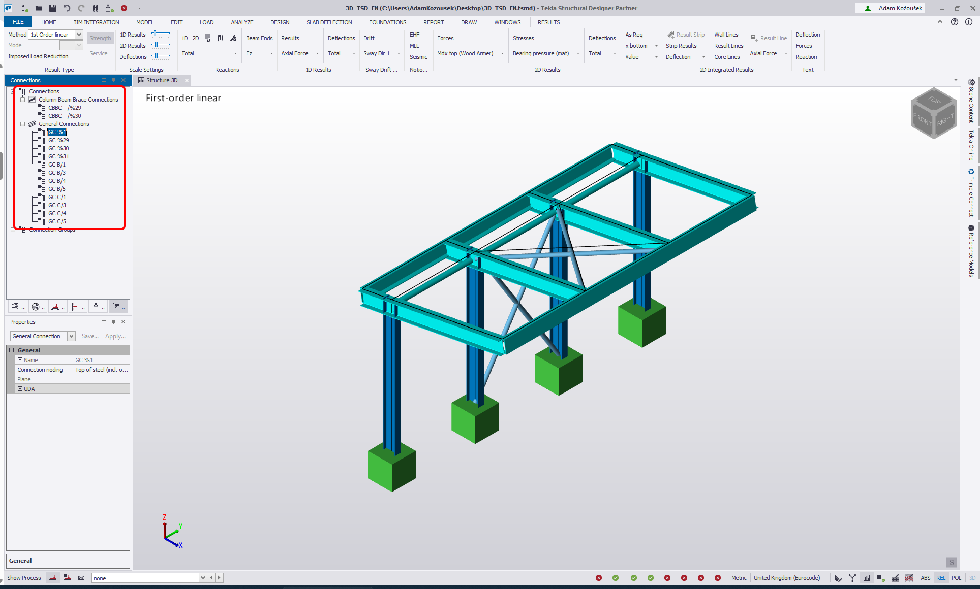
This populates the model with viable connections listed in the Connections window and as connection boxes in the 3D scene.
Second, export the connections to IDEA StatiCa Checkbot.
There are three ways to do this:
1 - Right mouse click on an item in the Connection window and select Export Connection to IDEA StatiCa

2 - Right mouse click on the connection box and select Export Connection to IDEA StatiCa

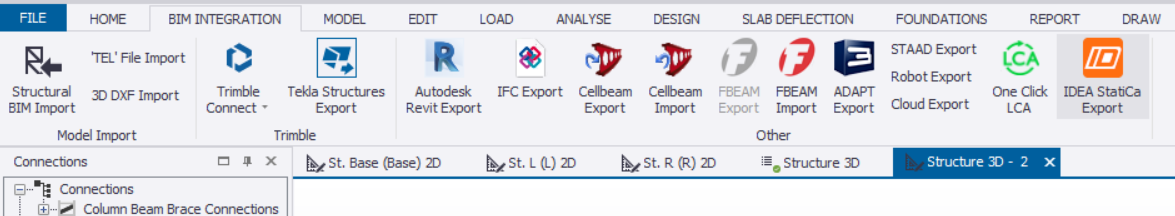
3 - Navigate to the BIM Integration tab and select IDEA StatiCa Export.
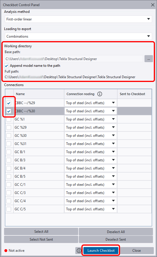
Checkbot Control Panel opens. You can change the path to the folder that will be created for the Checkbot project - change the Base path to the folder where your Tekls Structural Designer project is saved and tick Append model name to the path.
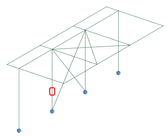
Select the anchoring nodes CBBC --/%29 and CBBC --/%30 and click Launch Checkbot.
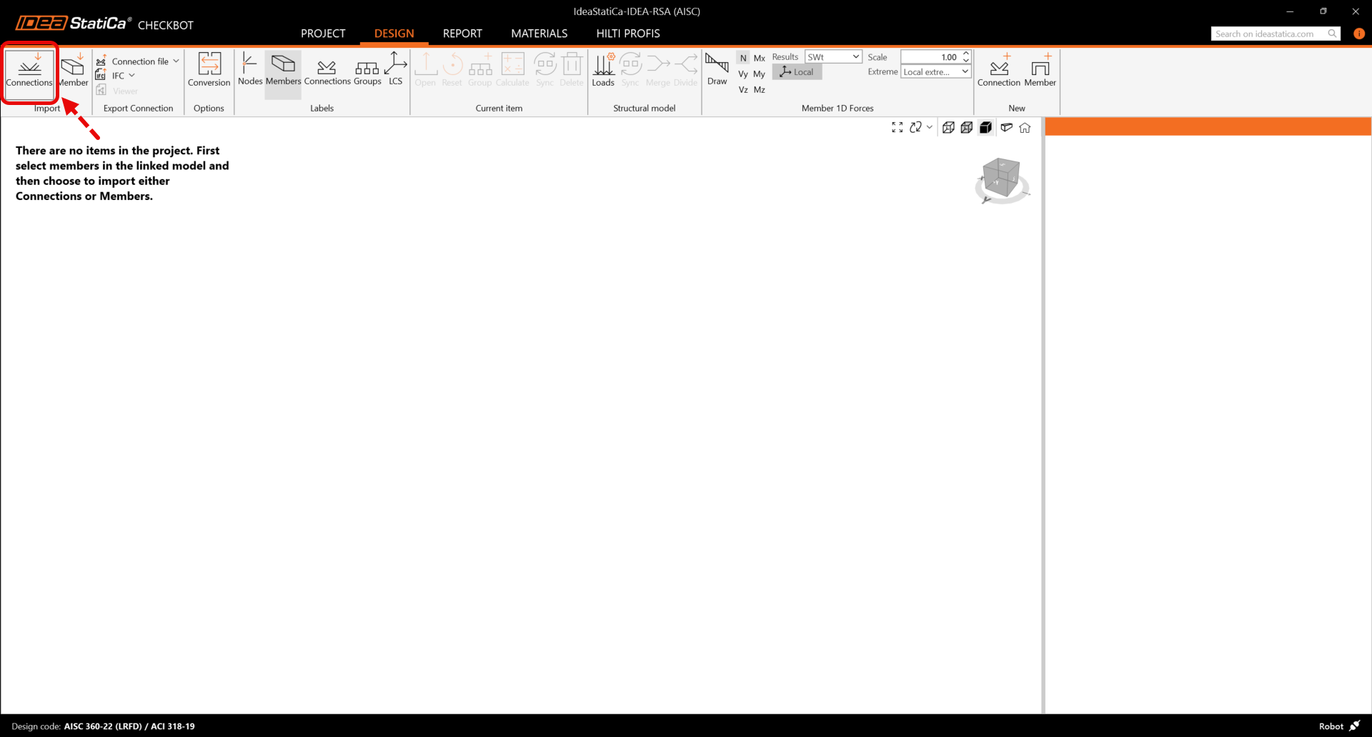
Import
Then in Checkbot select Connections.
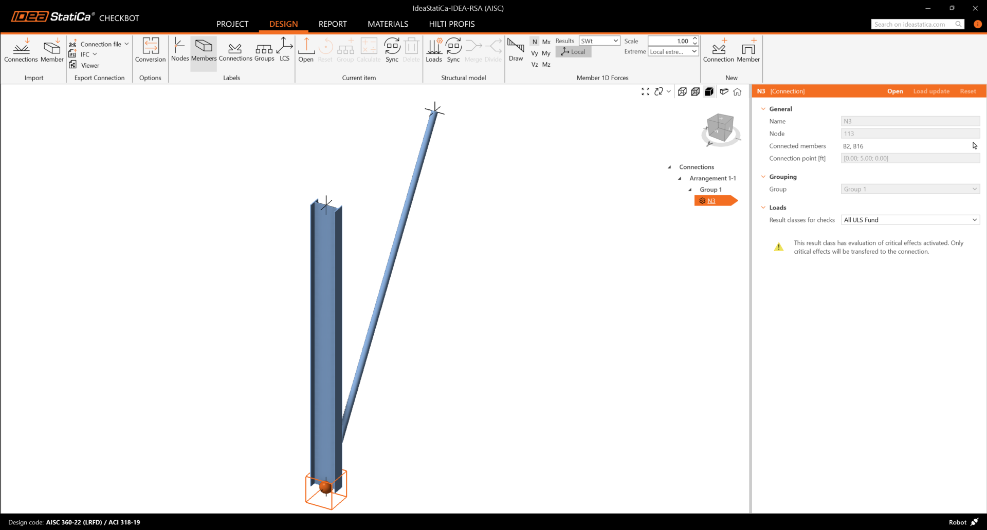
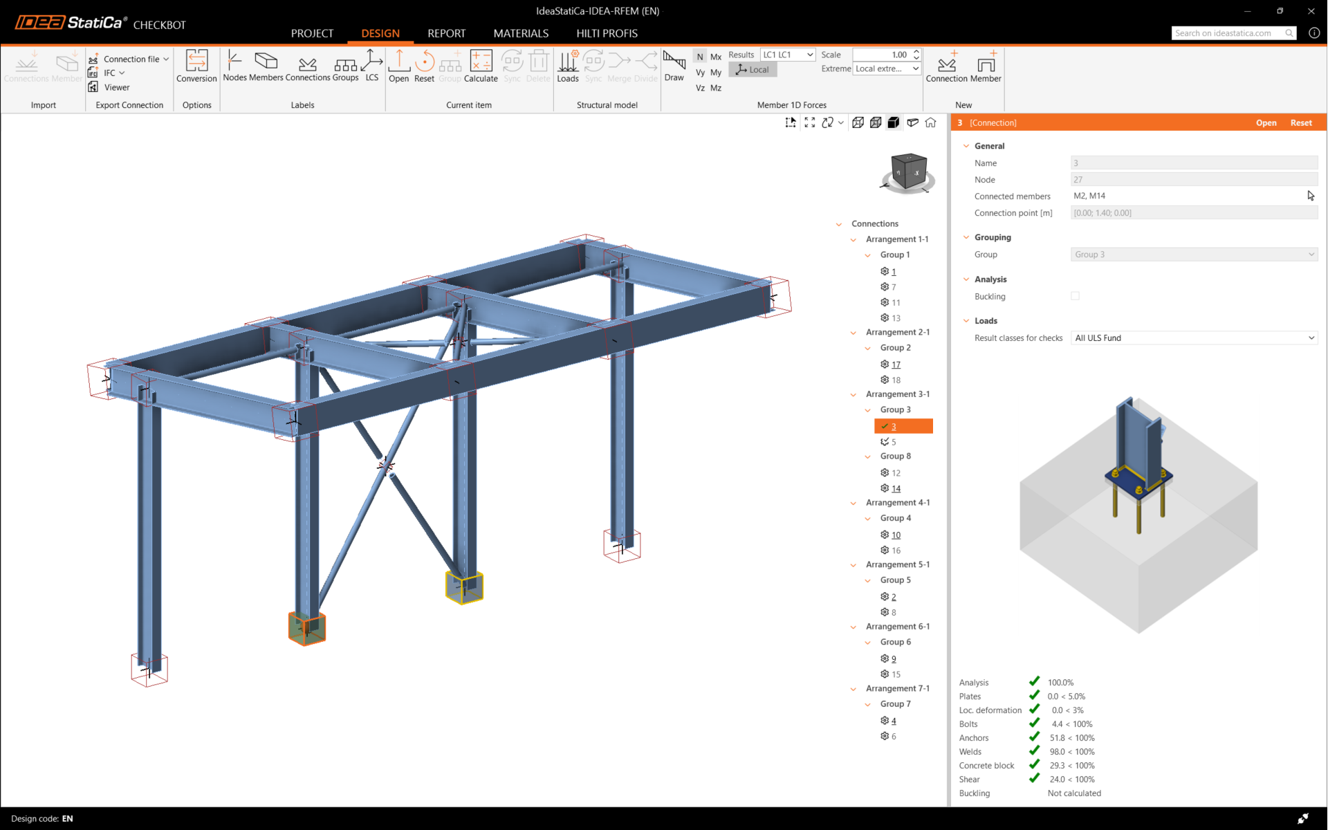
This will import the column and its load effects into Checkbot - with the same coordinates, orientations, and section sizes as per the FEA model.
Please note that your node and member numbering might be different.
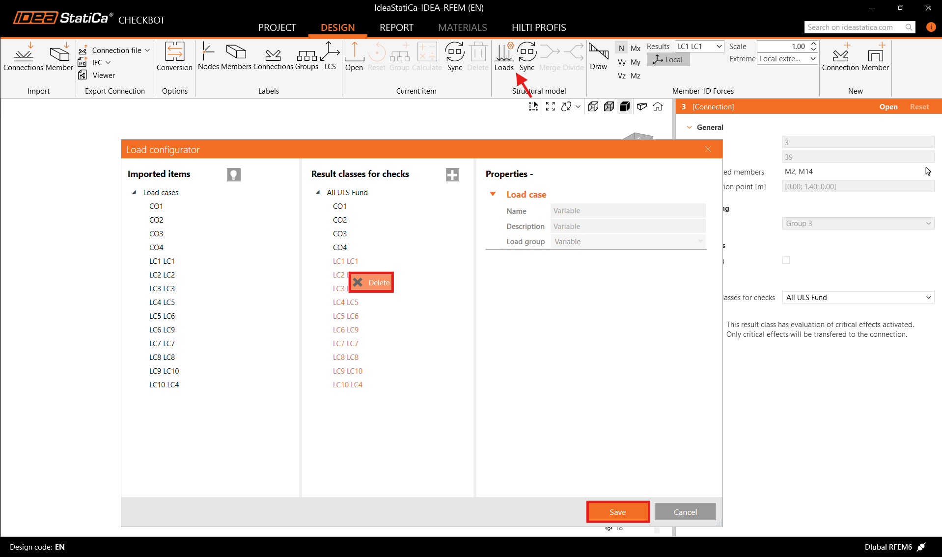
Before running the analysis, make sure to review the Result classes for checks and adjust the load cases accordingly. In the Load configurator dialog, you can see all imported load cases and load combinations on the left and the result classes used for checks in the middle. If some load cases are not relevant for your design verification, exclude them by right-clicking on the selected loads and removing them from the result classes list.
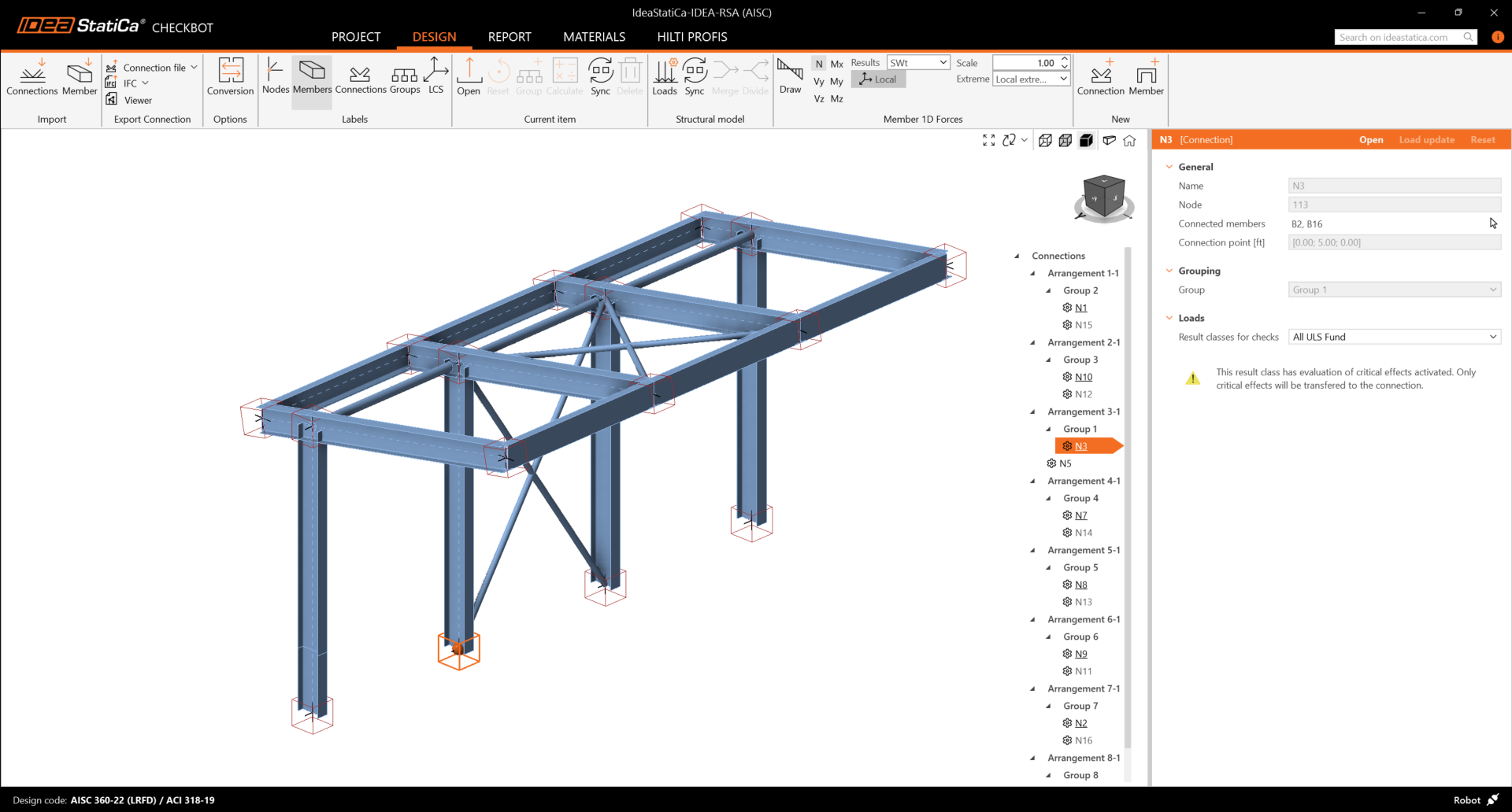
Please note the 3D workspace is designed to show an overview of the imported structure and not a detailed view of the actual connections. For more information on Checkbot, see here.
For several FEA solutions, you can also import multiple connections into Checkbot in the same manner as above. Instead of selecting one node and the connected members, you can select multiple nodes and members and import them all at once.
Geometry
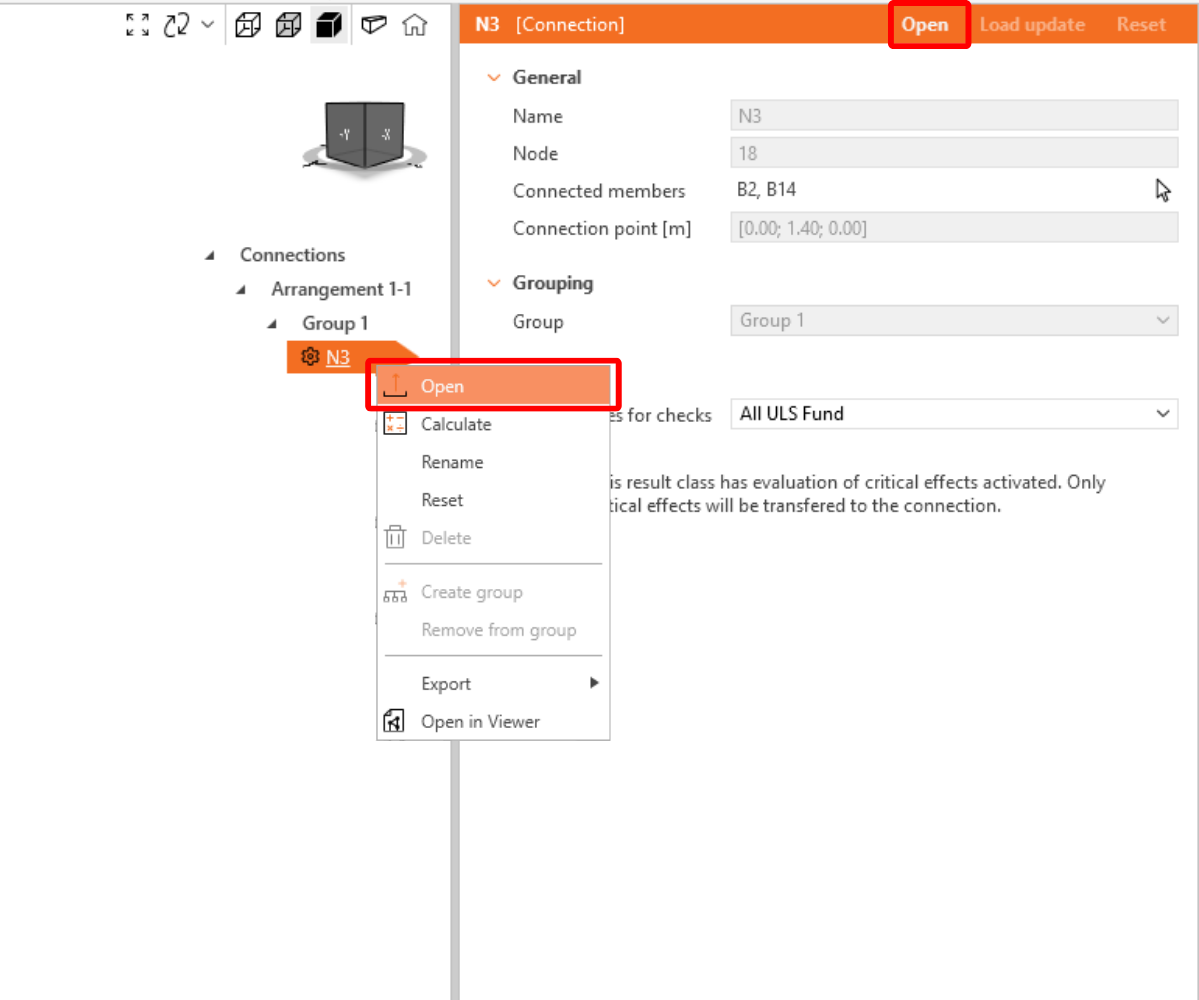
In the list of project items under Connections and with a connection highlighted in Checkbot you can either right-mouse click and select Open or click the ribbon command Open to start designing, code-checking, and reporting.
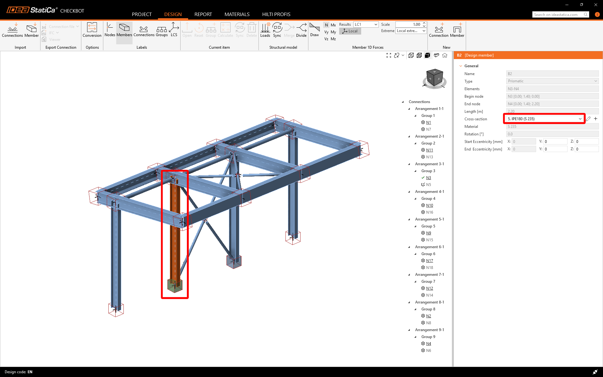
The settings of members are taken from the original FEA application. You can, however, change the section size of any member on the main Checkbot screen, but this will break the link with the FEA application in this session unless it's synchronized again.
The imported connection is opened in the IDEA StatiCa Connection application.
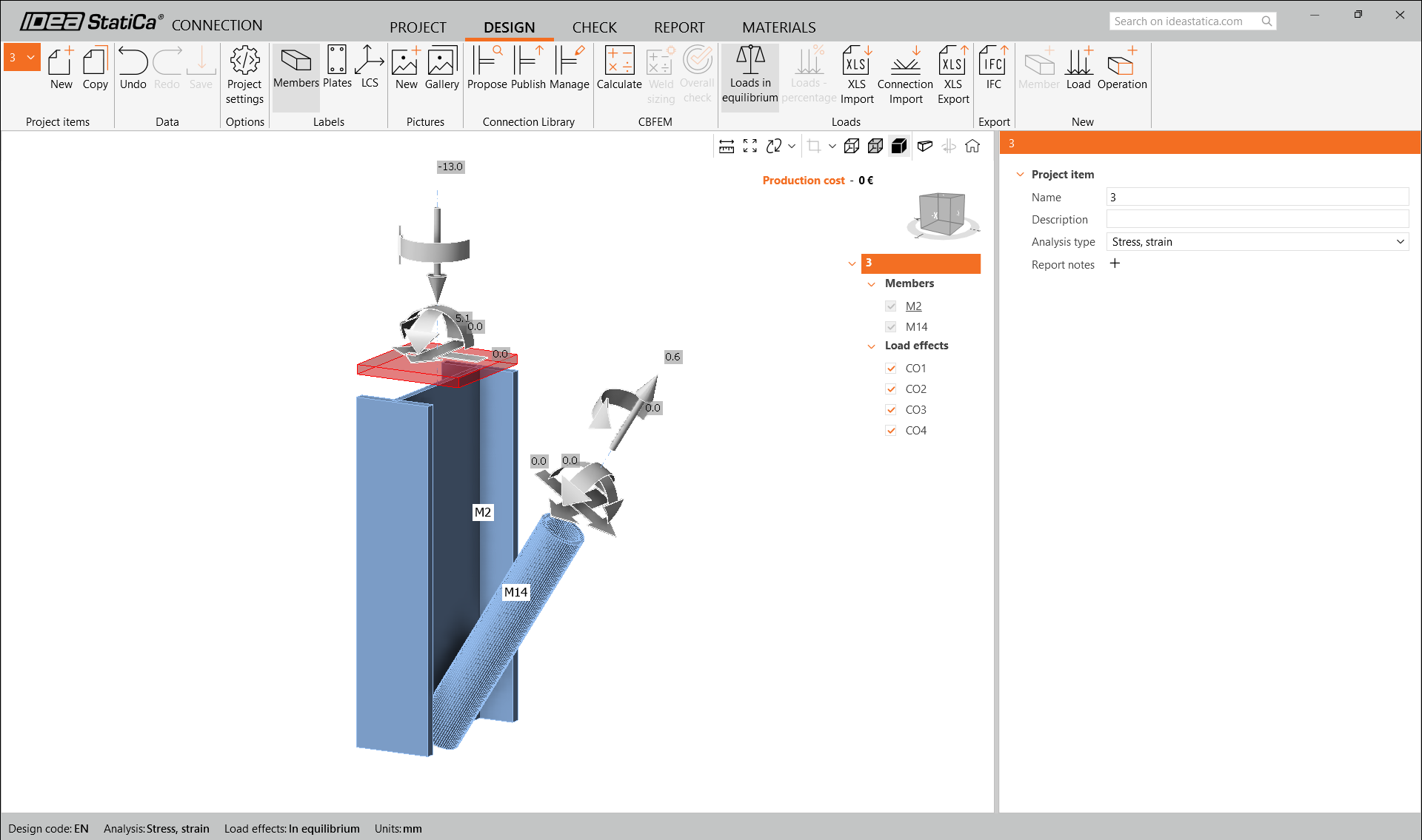
You may see none or different Load effects from your FEA solution, depending on how the load case combinations have been defined. By default, IDEA StatiCa will choose the most critical for code-checking purposes. (* Some BIM solutions are not able to store the load case combination results)
For more information on Load effects, see here.
Design
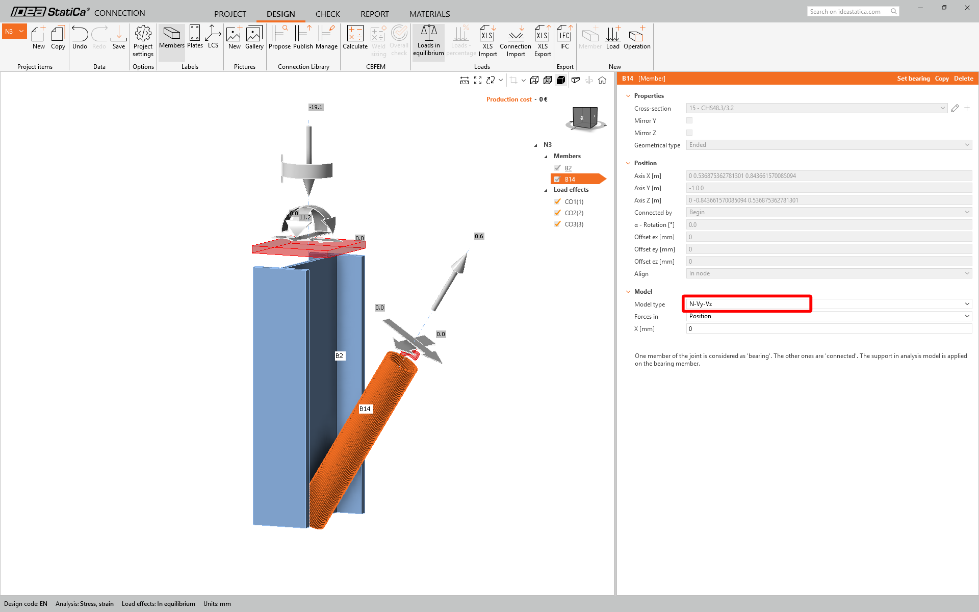
We are going to be using a single bolt connection for the diagonal brace. For this type of connection, we must also change the Model type of the brace member to N-Vy-Vz. Select the brace in the list of Members and modify the Model type in the drop-down list.
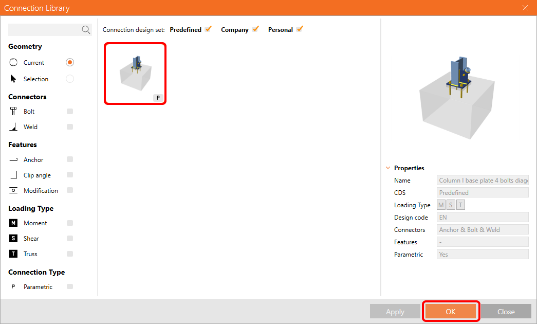
We are going to use the Connection Library to generate a connection. Select Propose and IDEA StatiCa will put forward possible solutions for the current geometry.

Connection Library shows you the possible solutions for the current geometry. Choose the template Column I base plate 4 bolts diagonal bolted weak and press OK.
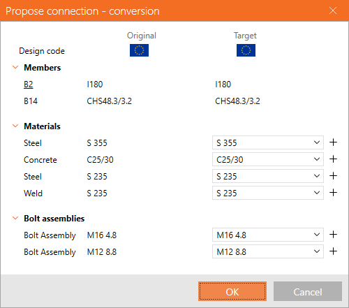
Accept the proposed values in the conversion tab and press OK.
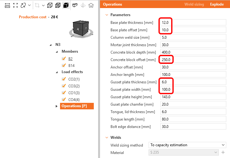
Edit the parameters of this template to fit the desired design – Base plate thickness to 12 mm, Base plate offset to 10 mm, Concrete block offset to 250 mm, Gusset plate thickness to 6 mm, and Gusset plate width to 100 mm.
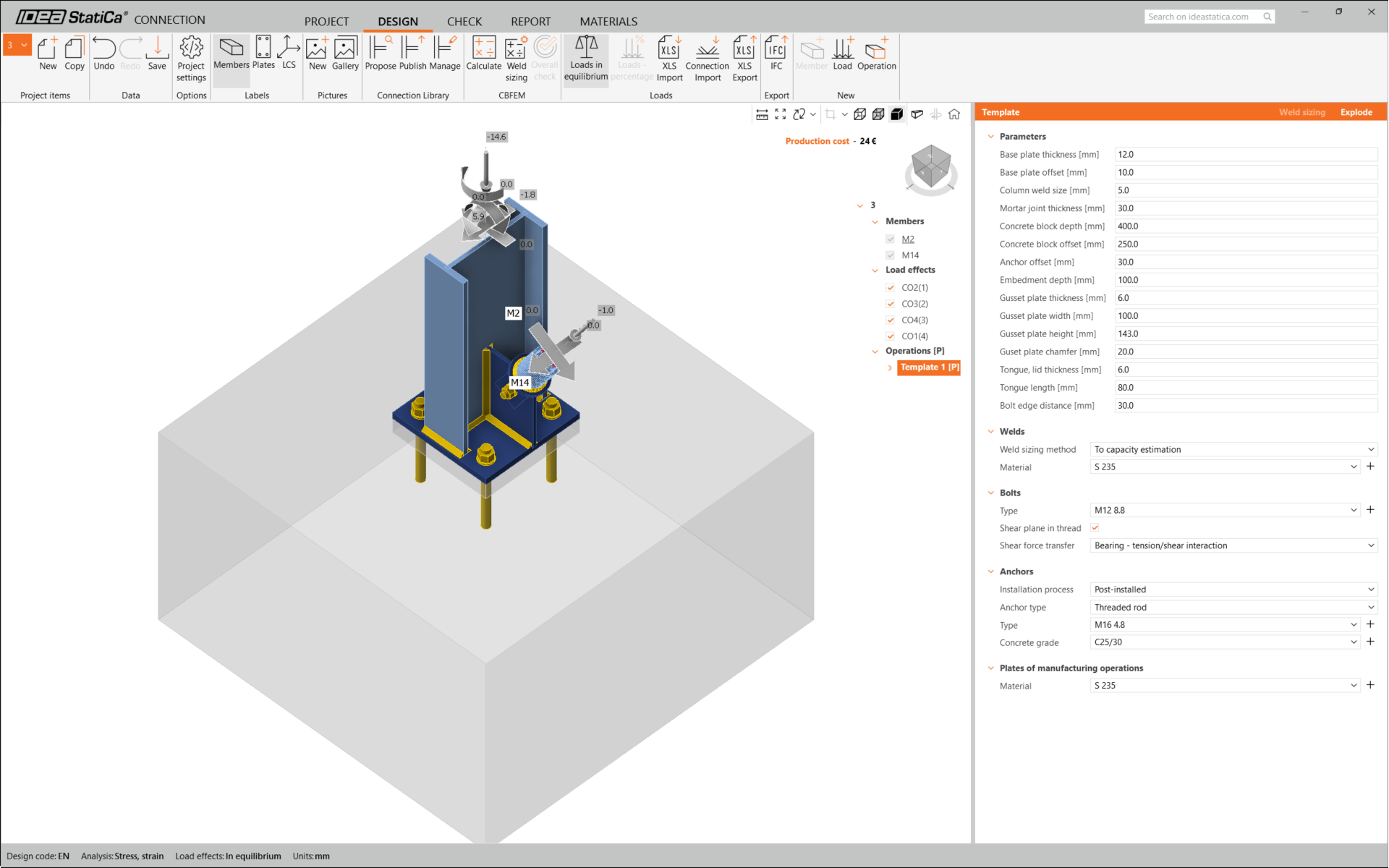
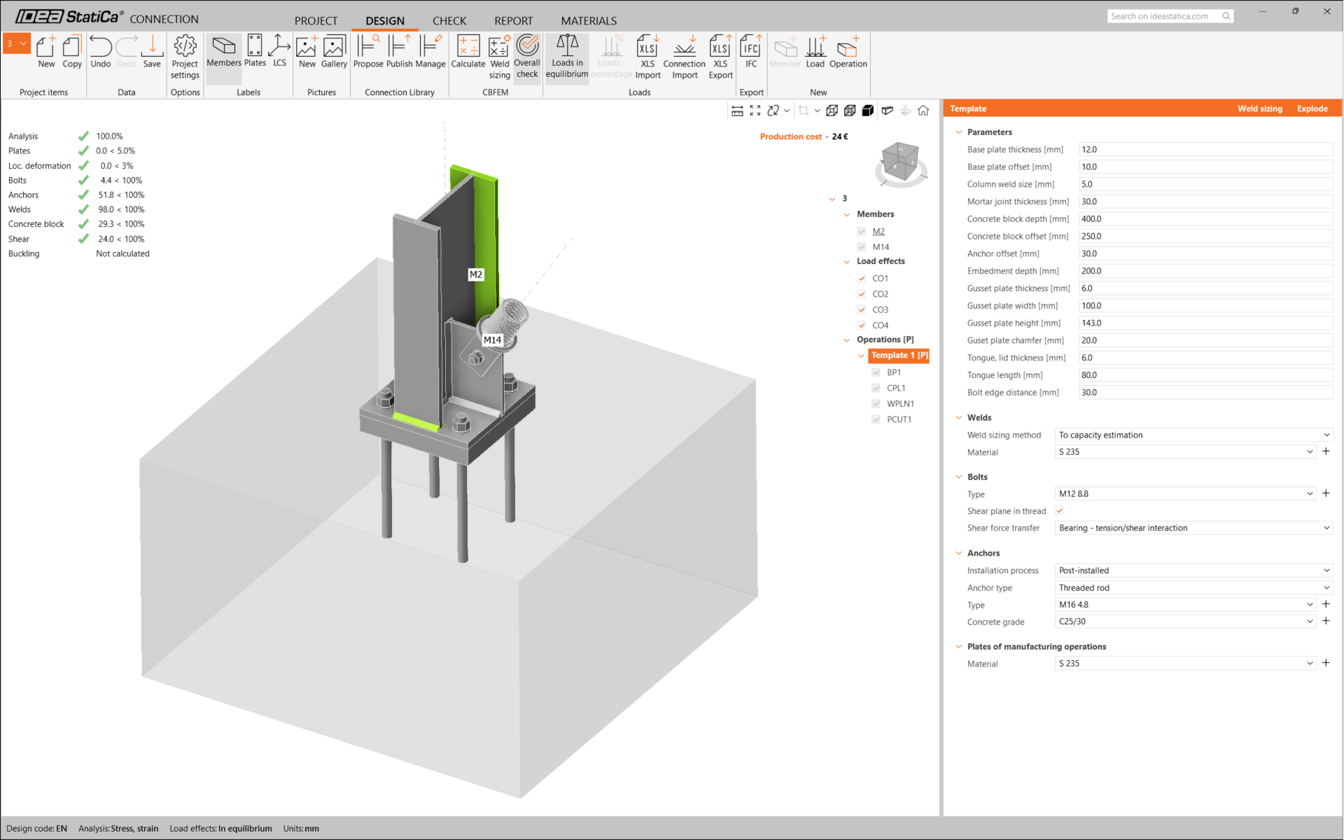
This is what the initial connection looks like.
That completes the design of the connection for the column base plate with a diagonal brace.
Code-check and Report
Now run a code-check using the Calculate icon in the CBFEM panel from the top ribbon.
Within IDEA StatiCa Connection, you can carry out many different types of analysis and code-checks. For more information, please see here.

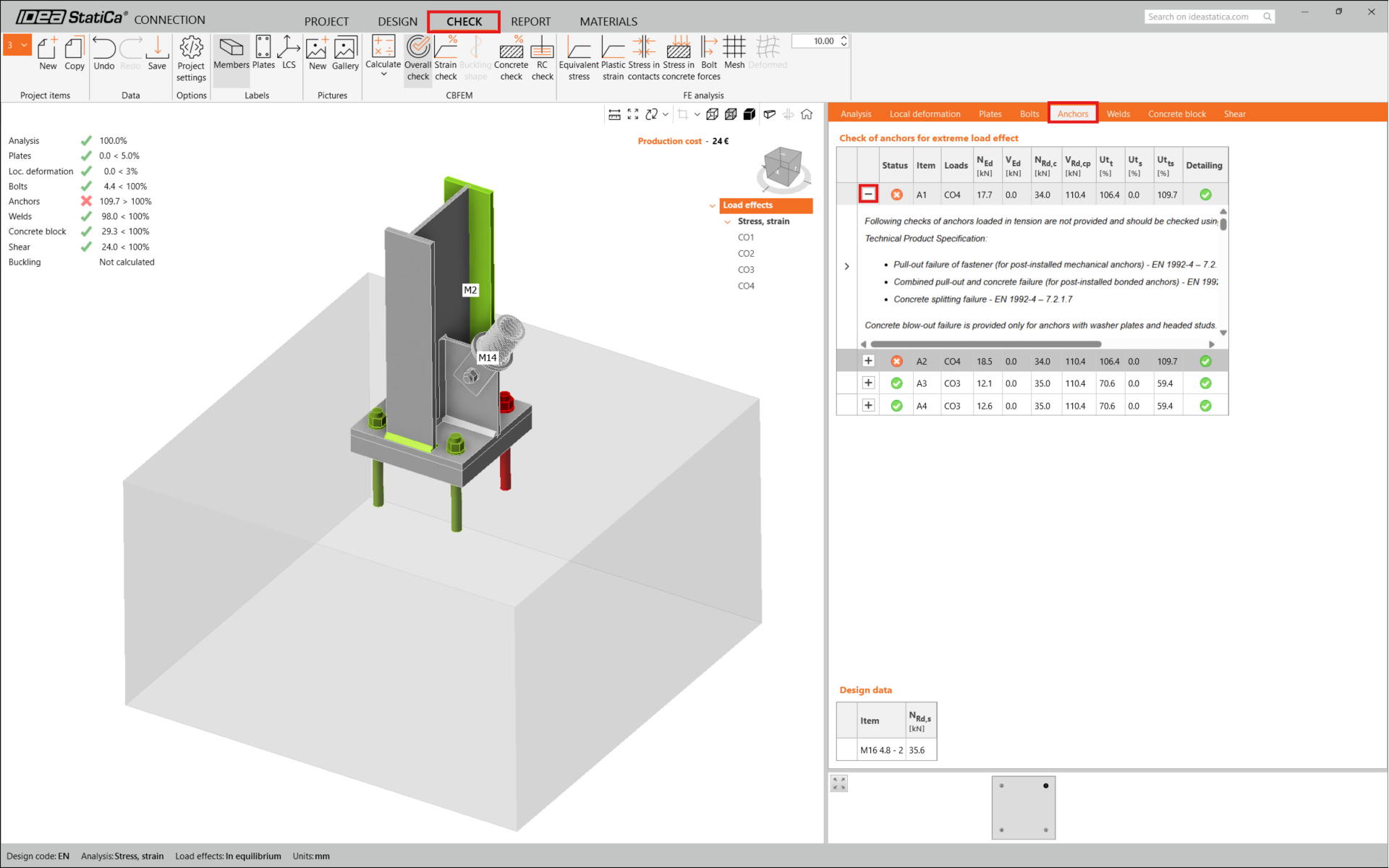
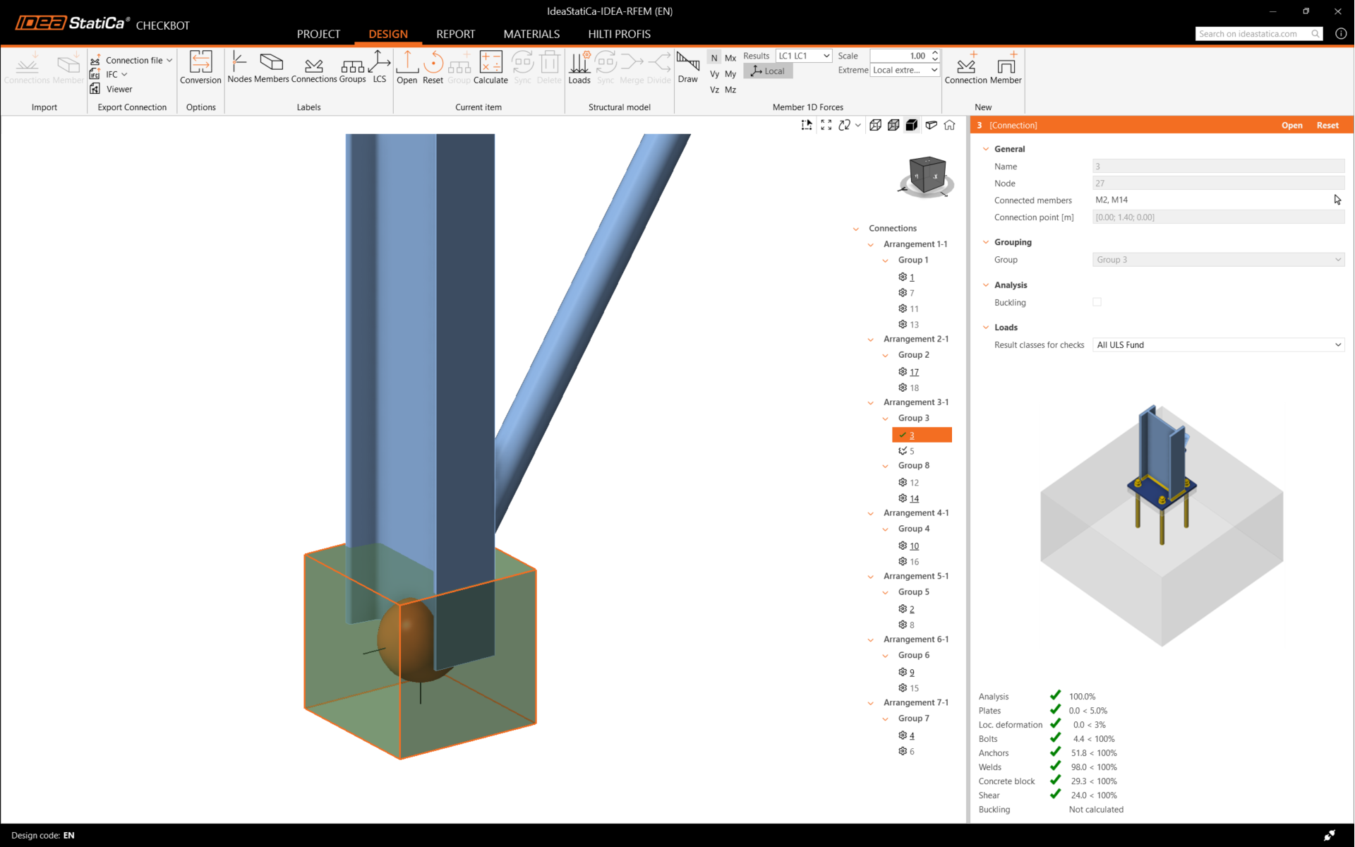
The results might not be acceptable. In this case, the anchors fail because of their low design capacity.
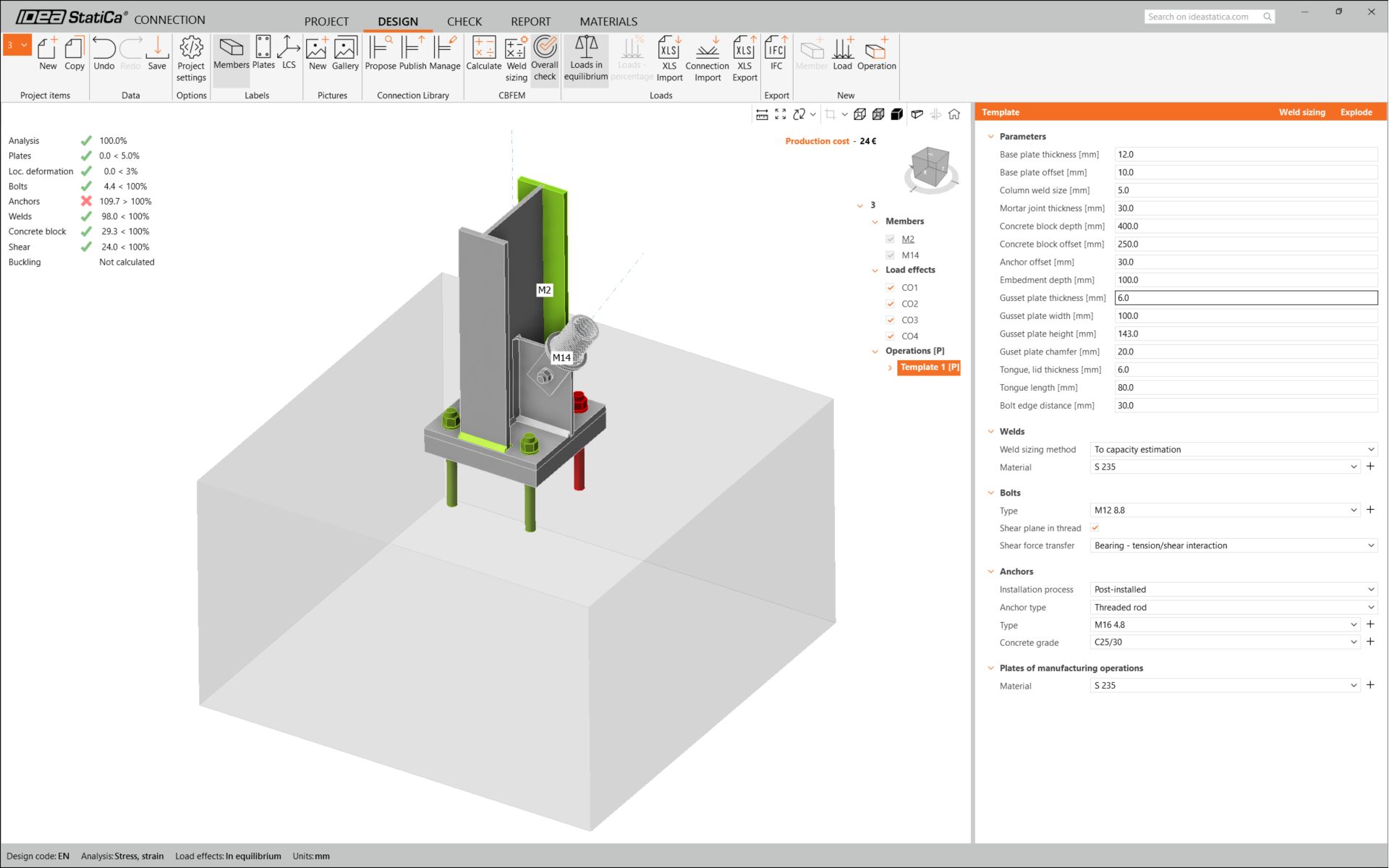
You can go to the Check tab to review the results and take a closer look at the anchors by expanding the calculation using the '+' symbol. You can see that the anchors are failing in tension in the concrete block.
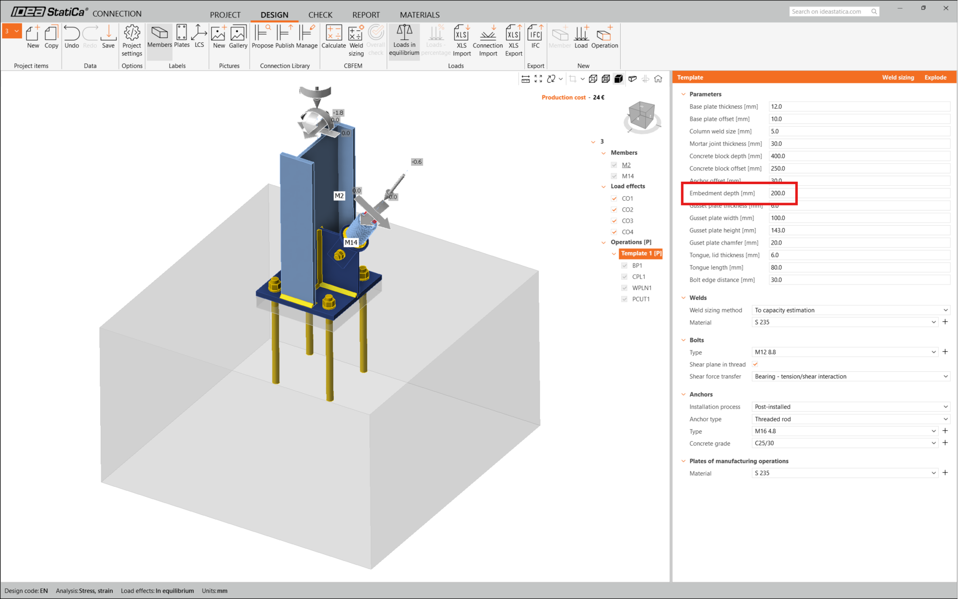
We must optimize the design to find the passing solution. Go back to the Design tab, click on the operation, and change the Anchoring length to 200 mm. Then run the analysis and code-check again.
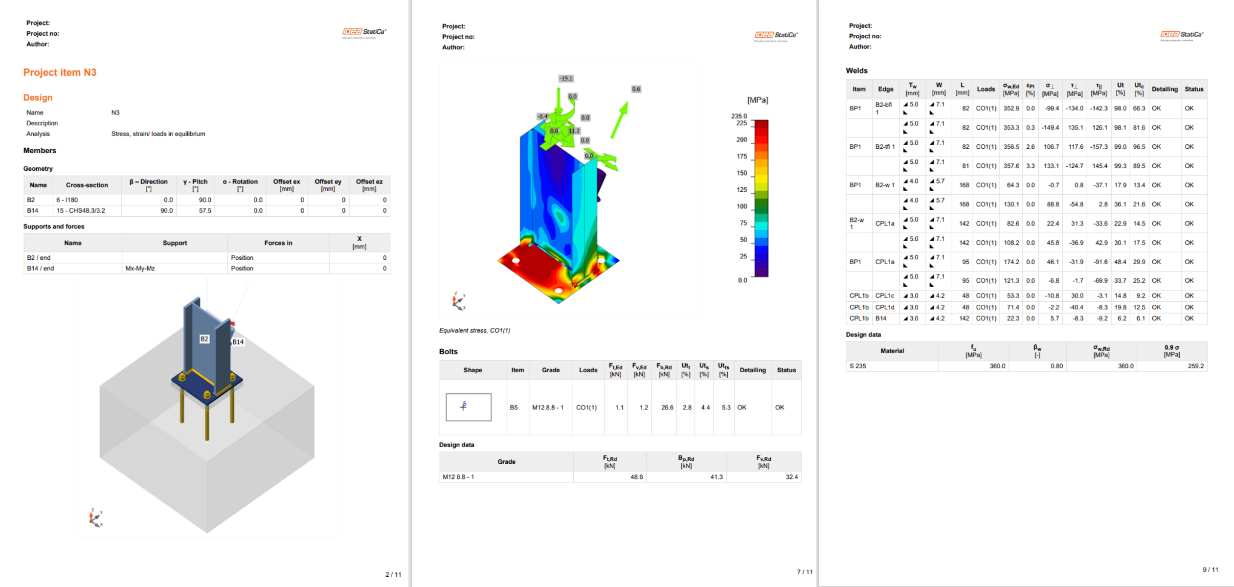
Once the code-check is finished in the Report tab, you can create the report containing results and diagrams for your connection model.
The report can be printed or saved in several formats. For more information, please see here.
Save this connection and switch back to the Checkbot window (you can keep the Connection window open).
In Checkbot, you will see a green tick next to the connection and the node box filled with green color. This means that the connection has passed all code-checks. In the Connection panel, you can also see a representation of the connection and a summary of the code-check results.
In the example below, you can see that only one connection has passed the respective code-check while the remaining connections have yet to be designed.
You can continue with the design of other connections, either one by one or using the bulk workflows.
Synchronize connections
Sometimes, there are changes to your FEA model, such as different member cross-section or increased load. These can be synchronized between Checkbot and the FEA model.
There are two possible alternatives:
- Synchronize the Current item (if one or more joints are selected)
- Synchronize the whole imported Structural model
To test this feature, you can change a member cross-section in your FEA application. Remember to re-analyze the FEA model to synchronize fresh results as well.
In Checkbot, select the designed connections (there may be more than one) and from the Current item panel select Sync.

The Checkbot project will be updated. The previously finished connection design is preserved, but the code-checks will be invalidated. You can see that the column is now updated - matching the change in the FEA model.
Simply code-check the highlighted connections again by selecting Calculate from the Current item panel.
If the connections do not give the desired results, then you can open them again to optimize the design (i.e. strengthen if they fail the code-check or lighten if the utilization is too low).
Bigger changes in the FEA model might require synchronization of the whole structural model in Checkbot, instead of just the current item.

Please note that newly added members or loads can not be synchronized, and a new Checkbot project has to be created.
You have successfully linked Tekla Structural Designer with IDEA StatiCa Connection via Checkbot.
Read more about the known limitations for Tekla Structural Designer BIM link to IDEA StatiCa.