
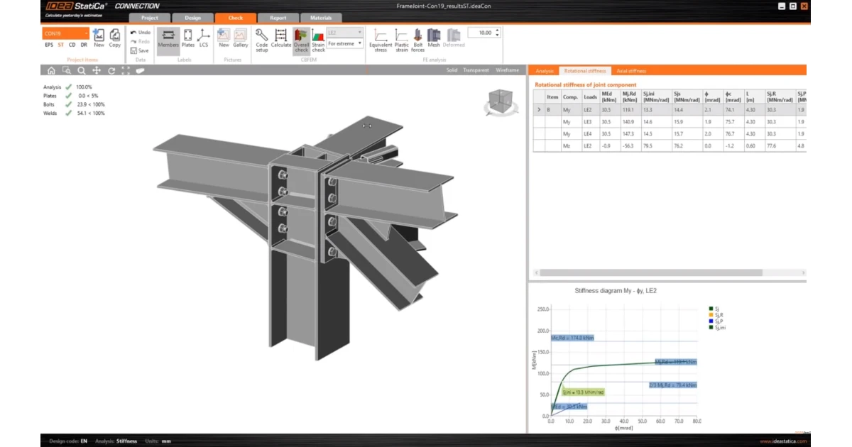


Use stiffness analysis in IDEA StatiCa Connection to determine whether the joints are pinned, semirigid, or rigid. As a result of the stiffness analysis, you will get the moment-rotation diagram and a table with important values. Based on the curve and a selected national standard, the joint is classified as:
- pinned
- rigid
- semirigid

Proper load definition
To get proper results from stiffness analysis, you can either calculate stiffness for each rotation separately, inputting a separate load case for My, Mz (alternatively N, and Mx).
Or you can apply a whole set of internal forces acting on the analyzed member, since all the other internal forces influence the results for each stiffness component (rotation) as well. For a detailed explanation, read the article Influence of shear force and normal force to rotational stiffness.
Applied forces must be greater than 1 kN/1 kNm/kip/kip.ft
Information needed for joint stiffness classification
- theoretical length of the member
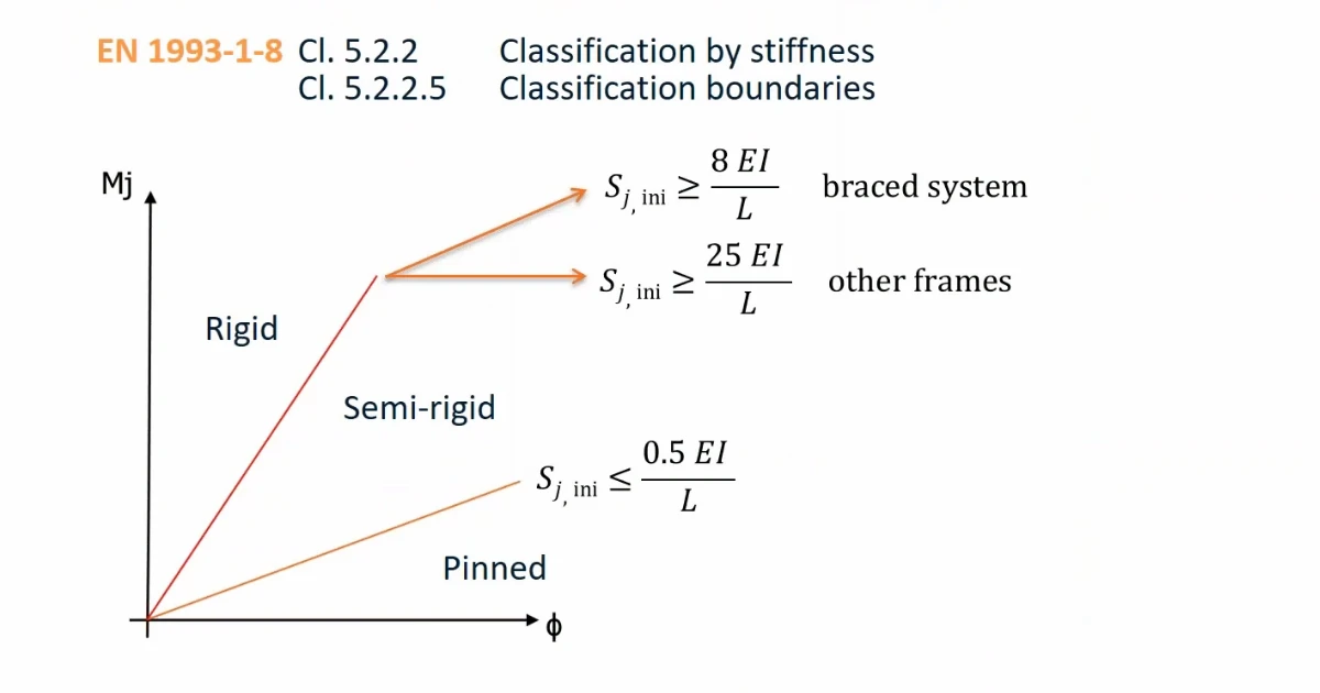
- distinguish between Braced and Unbraced structural system (for EN approach)
The Theoretical length for My and Mz [m] is defined as the node-to-node distance of the analyzed member and is used for classification only (not for calculating the actual stiffness values).

The braced system (braced frame) option is available for projects in Eurocode as per EN 1993-1-8 as there are different classification conditions for braced and unbraced systems.
Results obtained in the stiffness analysis
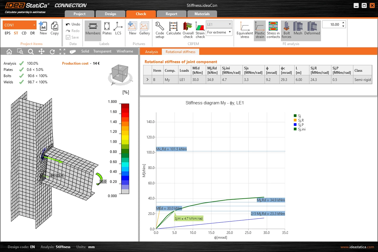
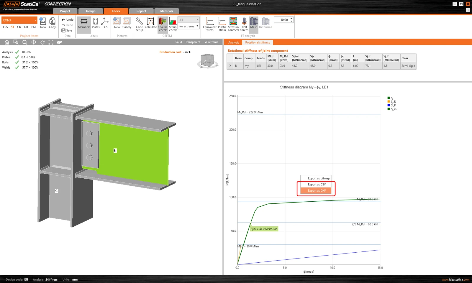
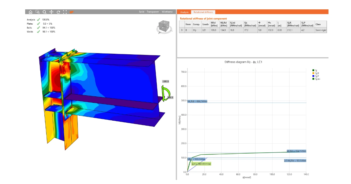
Two types of results are obtained: a table of numerical values and the stiffness diagram, which can be exported to CSV or DXF.
For each internal force component evaluated for rotational stiffness, the table lists the numerical values corresponding to each design load combination in individual rows. Depending on the line that is selected, the stiffness diagram will be for one or other component.

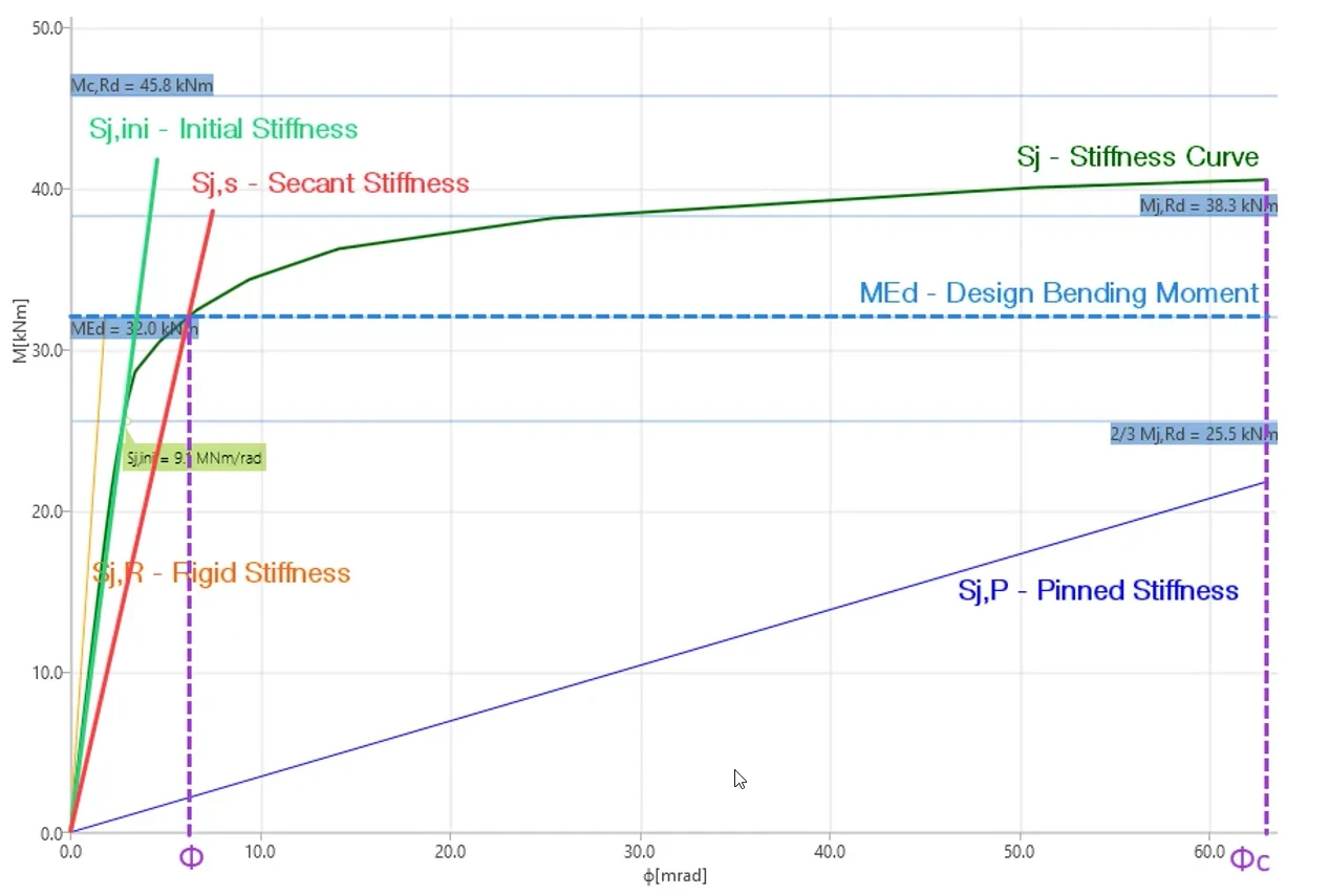
- MEd: Design bending moment introduced in the load combination, only relevant for the secant stiffness
- Mj,Rd: Bending resistance of the connection, for the purpose of the connection's yielding
- Sj,ini: Initial rotational stiffness, describing the linear stiffness bahaviour which is considered up to value of 2/3 Mj,Rd
- Sjs: Secant rotational stiffness, defined as the intersection of the design bending moment MEd and the stiffness curve of the connection Sj, relevant when MEd > 2/3 Mj,Rd
- : Rotational deformation obtained for the design bending moment
- c: Rotation capacity of the connection, limit is defined by failuare of bolts, failure of welds or 15% plastic strain of plates
- Sj,R: Stiffness value for the boundary between Rigid and Semi-rigid
- Sj,P: Stiffness value for the boundary between Semi-rigid and Pinned
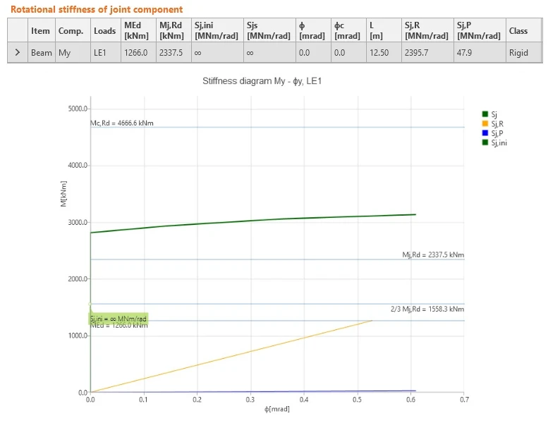
Note: If the initial stiffness Sj,ini and secant stiffness Sj,s show infinite stiffness, this means the stiffness curve is so steep that it's actually 90° in the diagram, so that the tangent results in infinity. This always means a rigid connection far from the border of the semi-rigid class, so the exact values are useless. In other words, the connection is absolutely stiff.
What to use in your global structural model in FEA?
The main information needed for your global model is the classification, to set the boundary condition between the members as a pinned (ideal hinge), rigid (ideally stiff), or semi-rigid (some stiffness).
For the semi-rigid class, you need to find the value representing the rotational stiffness of the joint between members. This is represented by the Sj,ini value from the Stiffness analysis results tab.
However, you always need to use engineering judgment to determine the appropriate stiffness value for your global structural model.
Sj,ini depends on the Mj,Rd value of the joint and the shape of the stiffness curve. Also, the CBFEM model for the Stiffness analysis differs from the one used in the EPS analysis, which can result in different Mj,Rd of the joint and further tuning of the connection model for the Stiffness analysis.
For more details, read the article Connection stiffness and its use in global analysis.
Where to find more information on Stiffness analysis
There are several sources of information to read about this type of analysis. We recommend reading the general part of the Theoretical Background, the blogpost Why bother with connection stiffness and/or watching one of our webinars on the topic (see below).
To combine the stiffness results with your global FEA model, watch How to put rotational stiffness into your FEA model video.
At the end of the article, you can find several step-by-step tutorials.
Model for stiffness evaluation
To evaluate the rotational stiffness kjoint of the connection itself and the corresponding rotation θ2, we subtract the part of the stiffness assigned to the deformation of members θ1 from the overall deformation θtot.
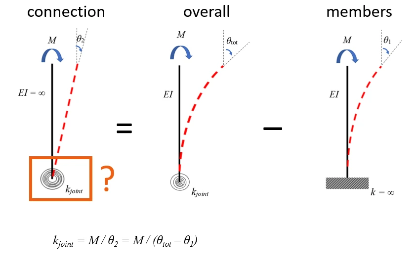
The rotation of members θ1 is evaluated on the model with ideally rigid connections among all members. The overall rotation θtot is evaluated on the model with real manufacturing operations.
The results obtained from the stiffness analysis correspond to the kjoint and θ2.
Theoretical Background
Read the essential information about stiffness analysis in our Theoretical Background. The above-mentioned settings are described in the general part of it.
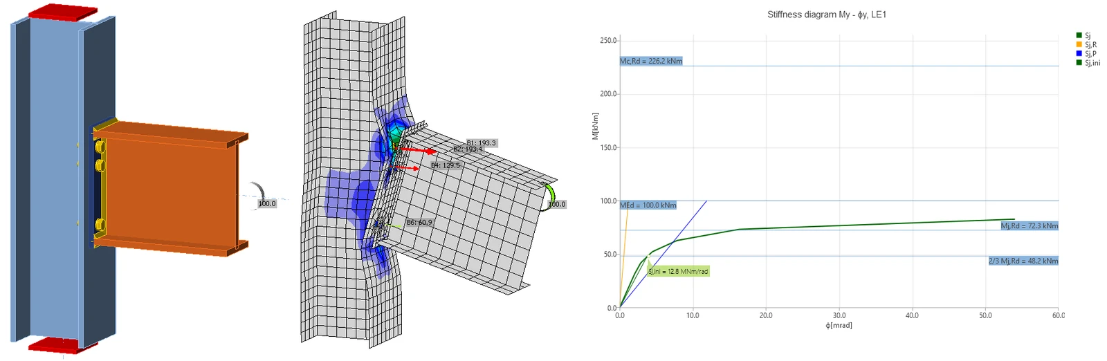
The general part of the Theoretical Background about the stiffness analysis and its results:
Stiffness analysis and deformation capacity of steel joints
Specific parts of the Theoretical Background for each of the supported national standards:
Other articles on connection stiffness and verifications
You can find more detailed information and some verification studies in the following articles. Some of them are part of the book "Benchmark Cases for Advanced Design of Structural Steel Connections" written by prof. Wald and his team.
- Why bother with connection stiffness (blogpost)
Webinars and videos
In the past, we have held several webinars on the topic of the stiffness of the connection. Also, some other videos describe how to work in the application. You can find inspiration from real-life projects as well as hints for setting up your computational models correctly.
Connection Wednesdays - Stiffness classification
In this webinar, we briefly review the code requirements related to stiffness classification. Afterward, we endeavor to design the connections of an actual frame that will be initially designed as moment resisting. We employ a semi-rigid configuration and subsequently apply the predicted behavior to the global analysis structure. Throughout this process, we explore common questions and assess their impact on the design.
Connection Wednesdays - Game-changing joint stiffness analysis
During the webinar, you will see the whole workflow of modeling, loading, and code-check of one interesting steel joint.
Connection Wednesdays - Residence in Ružomberok joint
Platform joints should be usually pinned, but what if the reality is not so simple? How to input the joint stiffness analysis correctly? See the frame joint stiffness analysis and consequences of the stiffness to FEM model.
How to put rotational stiffness into your FEA model
The stiffness of the joint is a significant and indispensable factor in the design of the global structure for semirigid connections. The question is, where can I calculate the stiffness of the joint, and what stiffness should be used for my design?
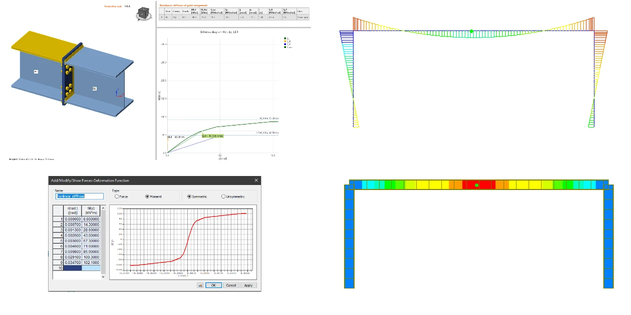
Design and code check of joint from Jakarta velodrome
The following webinar recording explains how the stiffness analysis diagram is constructed, what the settings are, and what results you will get.
Updates in versions
The following features are part of our release notes of IDEA StatiCa and may be related to the stiffness analysis. Read more about the features in the dedicated articles under the link.
Rotational capacity limited by bolt and weld failure (Stiffness analysis) (version 21.0)

Export of moment-rotation curve to CSV and DXF (version 22.0)
Tutorials
We have created step-by-step tutorials to set up the model and run the analysis. Find the links to them below:
Stiffness analysis of a steel connection (EN)
Stiffness analysis of a steel connection (AISC)
Rotational stiffness of a haunched beam
Take the latest version of IDEA StatiCa for a test drive today
Get 14 days of full access, completely free.
Check out IDEA StatiCa for free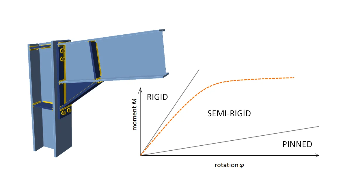
- Steel
- Connection design
- Member design
- Blog post
Why bother with connection stiffness
Read more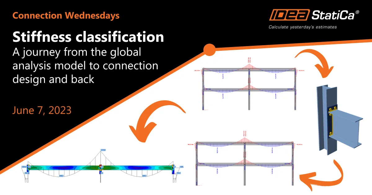
- Steel
- Connection design
- Webinar
Connection Wednesdays - Stiffness classification
Read more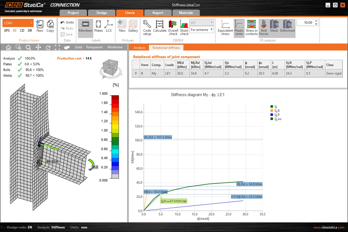
- Steel
- Connection design
- Knowledge base
Connection stiffness and its use in global analysis
Read more
- Steel
- Connection design
- Member design
- Theoretical background