
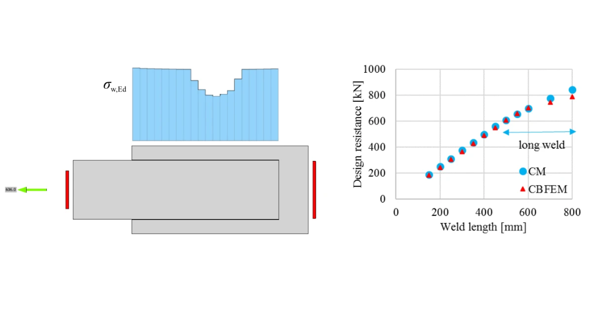


The weld resistance is reduced in connections to unstiffened flanges or in long joints due to concentrated stress. The plastic strain in a weld is limited to 5%, as in the plate. The design resistance of the fillet weld is determined using the Directional method given in section 4.5.3.2 EN1993-1-8:2006.
Read also the comprehensive article about welds here: Weld / Welds in IDEA StatiCa.
Stress development
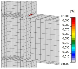
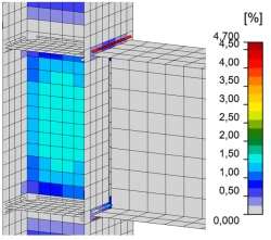
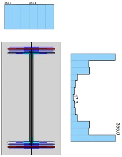
The strain distribution in a welded connection of a beam-to-column joint is shown below. The joint is loaded by the bending moment and the shear force. The design resistance is governed by yielding in the flange weld and is limited by 5% of plastic strain.
The progress of the weld stress/strain distribution reflects the plastic redistribution feature of the CBFEM model in IDEA StatiCa.
1/ Yielding starts in the flange weld
Fd = 0.63 Rd
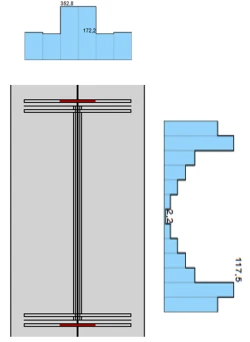
2/ Yielding starts in the web weld
Fd = 0.95 Rd
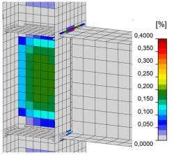
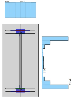
3/ Stress in welds at design resistance
Fd = Rd
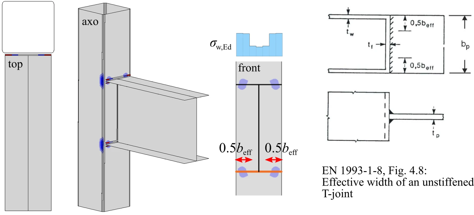
Effective width
The effective width of an unstiffened beam-to-column joint is shown below. The stress is concentrated in an effective width, while the weld resistance around the unstiffened parts is reduced. The stress distribution is shown for an open and a box or channel section.
I - section column
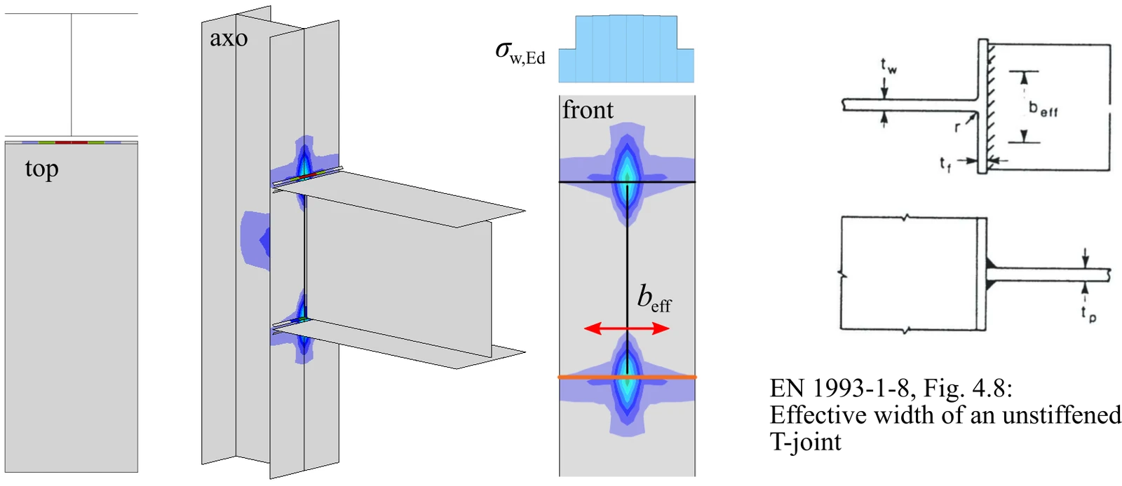
RHS - section column
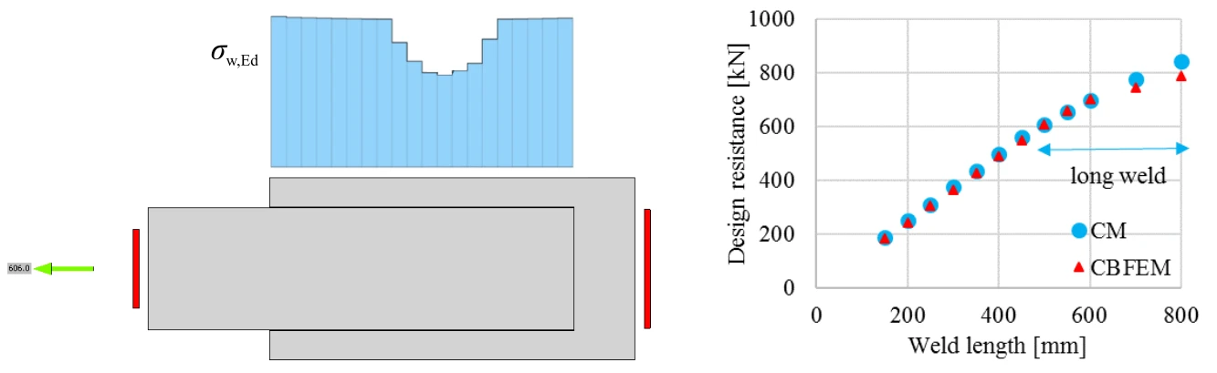
The non-uniform distribution of the stress along its length and the influence of the weld length on the design resistance is shown below.
Position of the weld finite elements
The weld model respects the properties of the real weld, like geometry, stiffness, and ductility. However, the position of the finite elements representing the weld and its constraints is simplified.
The position of the weld finite elements is as follows:
- Butt weld / CJP weld / Full penetration weld - at the axis of the connected plate element
- Double fillet weld / Double-Sided Weld - at the sides of the connected plate element (with symmetrical eccentricity)
- Fillet weld / Single-Sided Weld - at the axis of the connected plate element (eccentricity neglected)
Note: the same applies for the PJP weld / Partial penetration butt weld / Partial penetration groove weld
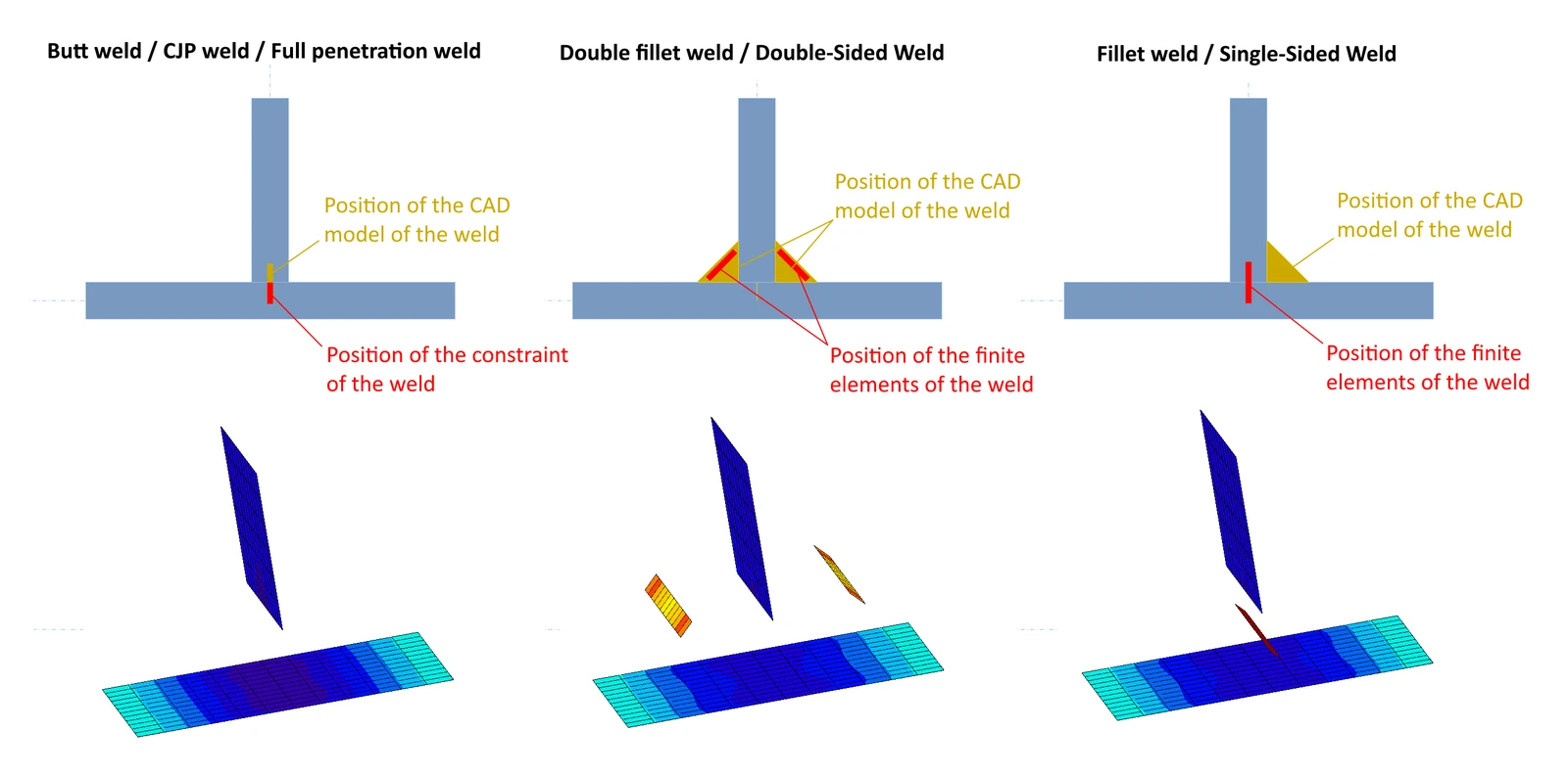
For the single fillet weld, the finite element model is simplified - the weld eccentricity from the connected plate axis is neglected. However, this error is negligibly small, and a single fillet weld as the only connector between two structural parts is not allowed as per code, since it works as a hinge (e.g., EN 1993-1-8, cl. 4.3.1.1 or cl. 4.7.1).
Limitations: There can be only one weld object defined on one edge of a plate. This means that it is not possible to define a weld of a different size on each side of a plate edge, nor to define a shorter/partial weld on one side of a plate than the other.