Partially loaded areas (PLA)
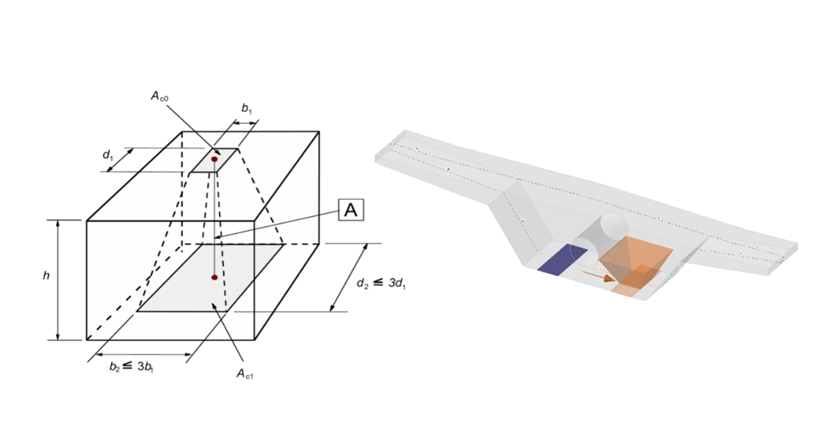
When designing concrete structures, we meet two large groups of partially loaded areas (PLA) - the first of these comprises bearings, while the other consists of anchoring areas. According to currently valid standards for the design of reinforced concrete structures EN 1992-1-1 chap. 6.7 (Fig. 34), local crushing of concrete and transverse tension forces should be considered for partially loaded areas. For a uniformly distributed load on an area, Ac0, the compressive capacity of concrete may be increased by up to three times depending on the design distribution area Ac1.
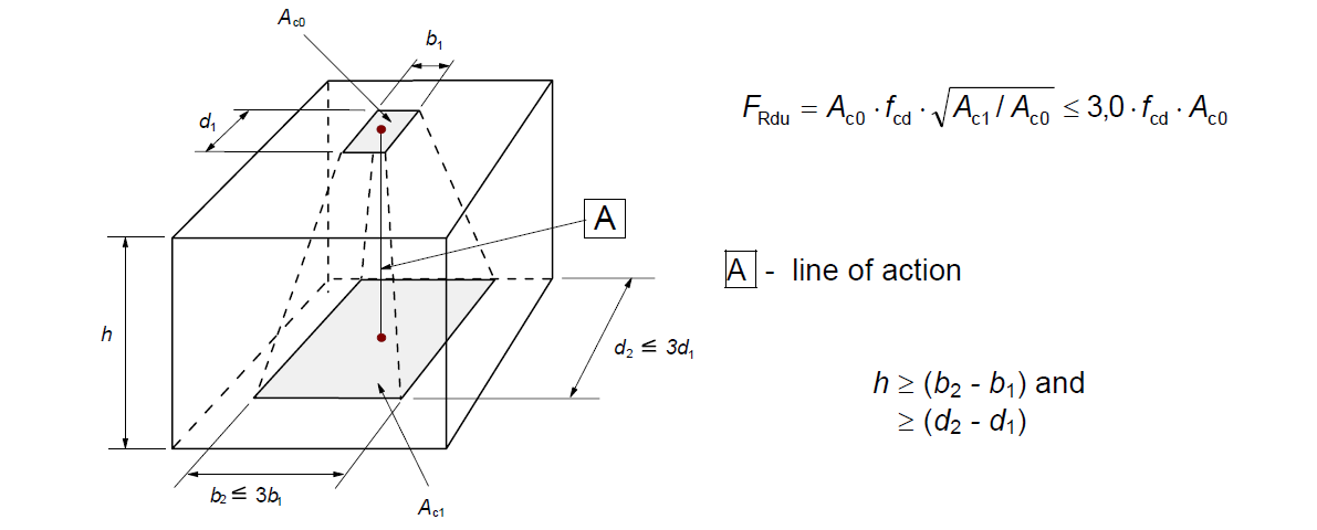
\[ \textsf{\textit{\footnotesize{Fig. 34\qquad Partially loaded areas according to EN 1992-1-1.}}}\]
The partially loaded area must be sufficiently reinforced with transverse reinforcement designed to transmit the bursting forces that occur in the area. For the design of transverse reinforcement in partially loaded areas, the Strut-and-Tie method is used according to the Eurocode. Without the required transverse reinforcement, it is not possible to consider increasing the compressive capacity of the concrete.
Partially loaded areas in the CSFM
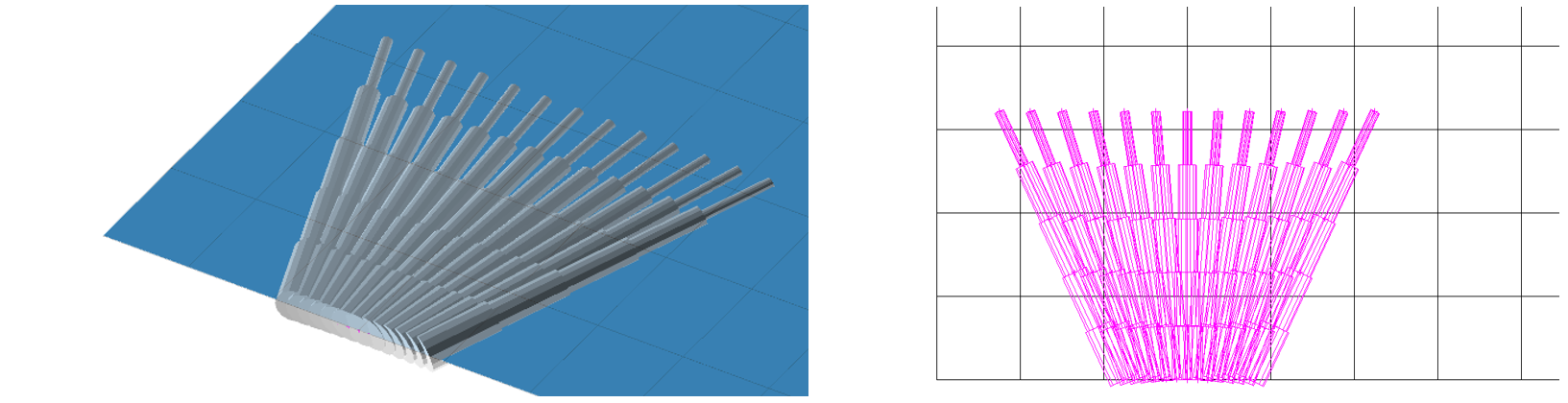
\[ \textsf{\textit{\footnotesize{Fig. 35\qquad Fictitious struts with concrete finite element mesh.}}}\]
Using the CSFM, it is possible to design and assess reinforced concrete structures while including the influence of the increasing compressive resistance of concrete in partially loaded areas. Because the CSFM is a wall (2D) model and the partially loaded areas are a spatial (3D) task, it was necessary to find a solution that combines these two different types of tasks (Fig. 35). If the “partially loaded areas” function is activated, the allowable cone geometry is created according to the Eurocode (Fig. 34). All geometric collisions are solved fully in 3D for the specified concrete member geometry and the dimensions of each PLA. Subsequently, a computational model of the partially loaded area is created.
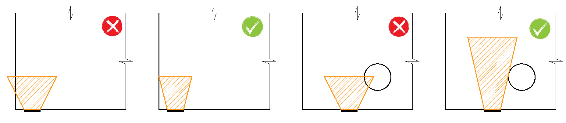
\[ \textsf{\textit{\footnotesize{Fig. 36\qquad Allowable cone geometries.}}}\]
The modification of the material model proved to be an unsuitable approach, which was mainly because the mapping of properties to the finite element mesh is problematic. It was determined that an approach independent of the finite element mesh is a more appropriate solution. Absolutely coherent fictitious struts are created for the known compression cone geometry (Fig. 35 and Fig. 37). These struts have identical material properties to the concrete used in the model, including the stress-strain diagram. The shape of the cone determines the direction of the struts, which gradually distributes the load over the PLA to the design distribution area. The area density of the fictitious struts is variable at each part of the cone, and it adds a fictitious concrete area in the load direction. At the level of the loaded area (Ac0), a fictitious area of concrete is added according to the ratio \(\sqrt{A_{c0} \cdot A_{c1}} - A_{real}\) (where Areal is an area of the support assumed in the 2D computational model), and this area decreases linearly to zero towards the design distribution area (Ac1). This solution ensures that the compressive stress in the concrete is constant over the entire cone volume.
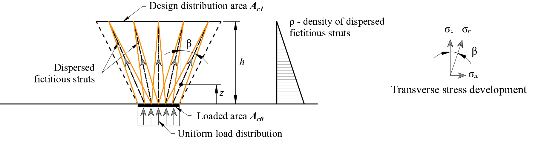
\[\rho \left( {\beta ,z} \right) = \left( {\sqrt {\frac{A_{c1}}{A_{c0}}} - \frac{A_{real}}{A_{c0}}} \right)\,\cdot\,\left( {1 - \frac{z}{h}} \right)\,\cdot\,\frac{1}{{\cos \beta }}\]
\[ \textsf{\textit{\footnotesize{Fig. 37\qquad Fictitious struts in the computational model}}}\]
The resistance of the partially loaded area is increased according to the ratio of the design distributed area and the loaded area laid in EN 1992-1-1 (6.7). It should be remembered that this is a design model that cannot precisely describe the stress state over a partially loaded area whose actual flow is much more complicated. However, this solution allows the correct distribution of load to the whole model while respecting the increased load capacity of the partially loaded area. In addition, it correctly introduces transverse stresses in this area.
While using the Partially areas loaded areas feature to simulate the increase of concrete compressive capacity, it is necessary to provide the code check separately according to EN 1992-1-1, section 6.7 (2). The transverse tensile forces (splitting forces) transferred by the reinforcement are automatically checked.