
Parametric design in IDEA StatiCa Connection - Single plate Shear connection
In this tutorial we will parametrize a simple Single shear connection with one bolt row.
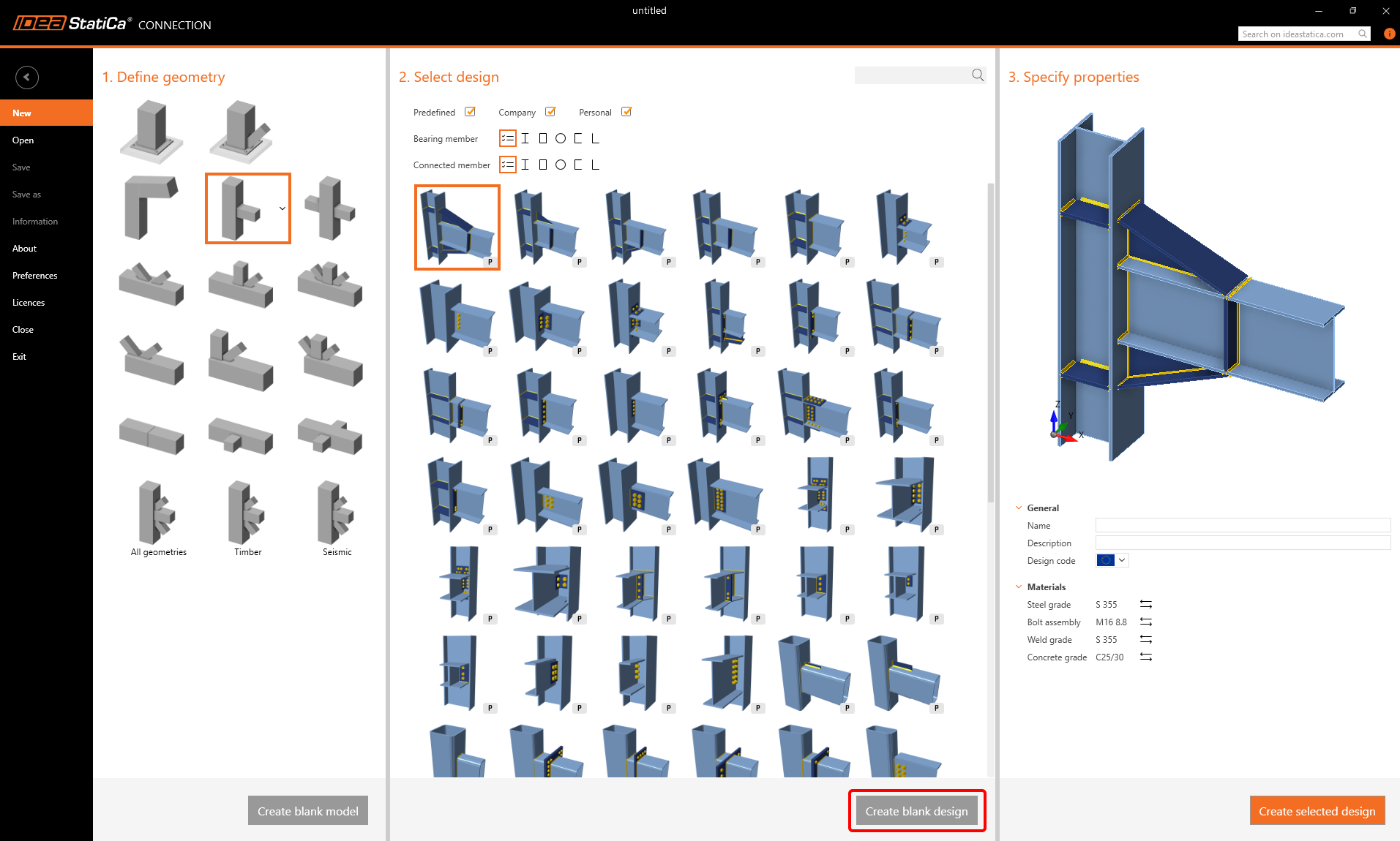
For this purpose, create a new joint without any operation (click on Create blank Design).
Apply the Operation Shear plate and switch to the Tab Developer.
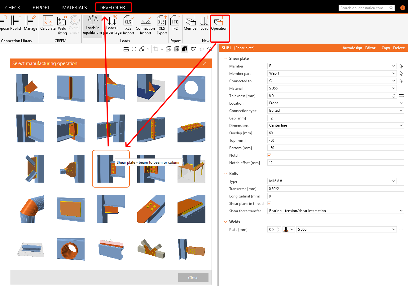

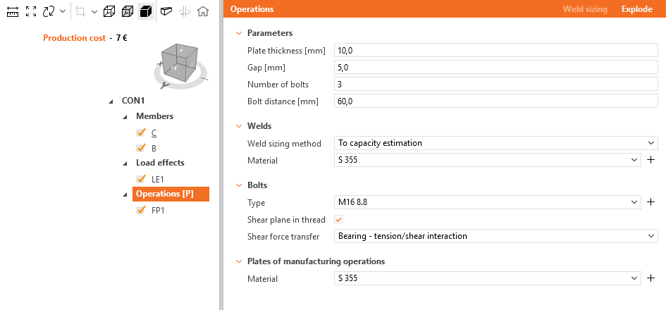
Instead of changing all these fields we can see in this Operation, we will focus only on following:
- Plate thickness
- Gap
- Number of bolts
- Bolt distance
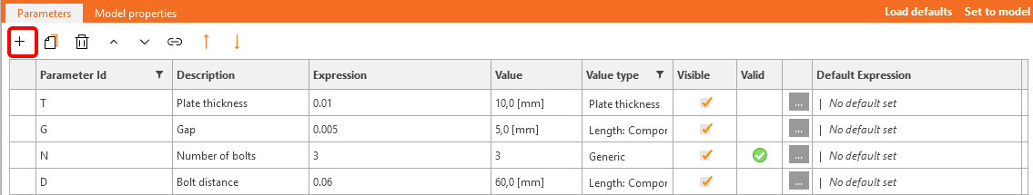
Click on the + button and fill in the fields according the following picture.
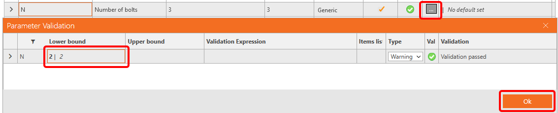
For the field Number of bolts, we would like set a warning to have an imput of at least two bolts. For this, set the Lower bound to the value 2.
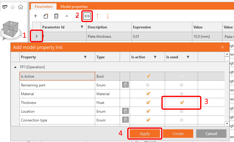
If you go back to the Tab Design, and select the Field Operations, you can see the parameters, we have set.
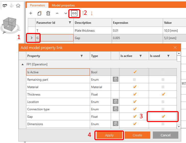
The parameters T (Plate thickness) an G (Gap) you can now directly link to the operation FP1.
As we have only one bolt row, we can calculate the plate overlap as bolt diameter x 2 x 2 according the EN code. To set it properly, visit the link to Reference Guide, positioned at the bottom of the Parameters window.
| O | Overlap | Round(GetBoltDiameter('FP1',0) *4,3) |
Next, link this parameter to the operation FP1.

You have set the width of the shear plate, now its time to set the height of it. Again, we would also like to set a warning not to exceed the beam dimension.
You have to calculate the edge distance of the bolt and the clearence of the web to get the height of the plate.
| E | Edge distance | Round(GetBoltDiameter('FP1',0) *2,3) |
| H | Cross-section height | GetValue('B', 'CrossSection.Bounds.Height') |
| F | Flange thickness | GetBeamPlateThickness('B', 'TopFlange') |
| H0 | Clearance | H-2*F |
| H1 | Plate height | (N-1)*D+E+E |
Enter the data according following picture and set H0 to the Upper bound in the Parameter Validation table.

As in the operation FP1 you do not enter the height of the plate, but the distance Top/Bottom set the value
-(H-H1)/2 for the parameter H2 and link it to the proper fields.

There is one more field, you need to set - the position of the bolts. According the number of the bolts (either odd or even) use following formula (Concat puts the number in correct format):
| Tr | Transverse | if(N % 2==1,Concat(0," ",D,"*",(N-1)/2),Concat(D/2," ",D,"*",N/2-1)) |

As the connection is a shear joint, we can assume that the shear forces are acting in the position of bolts and the Model type is N-Vz-My.
So add another parameter B with the value 'Bolts' and link it to the member B. In case, the position is changed, you can add a validation (CheckForcesIn('Bolts', 'B')).


For the Model type we create parameter M with the value 'N-Vz-My' and set a validation warning to GetValue('B', 'StaticBehavior') == 'DoNotActDirYRotZ'.

Now, you can go to the tab Design and strore your newly created parametric joint as a template, either in the personal or company set.

See below the finished model.
You have acquired the skills to utilize parameters, create parametric templates, and undertake fundamental parameter-related tasks.
Attached Downloads
- shear.ideaCon (IDEACON, 39 kB)